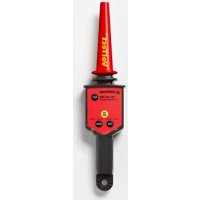
TIC300PRO - Detector Amprobe - Free user manual and instructions
Find the device manual for free TIC300PRO Amprobe in PDF.



| Product Type | Non-contact AC Voltage Detector |
| Brand | Amprobe |
| Model | TIC300PRO |
| LOW Voltage Range | 30 VAC to 1500 VAC |
| HIGH Voltage Range | 1500 VAC to 122 kVAC |
| Power Supply | 9 V Alkaline Battery |
| Dimensions (L x W x H) | 345 x 75 x 47 mm |
| Weight | 243 g |
| Voltage Indication | Visual (blue LED) and audible (beep) |
| Detection Ranges | LOW and HIGH, selectable by button |
| Self-Test | TEST button to check proper operation |
| High Voltage Use | With TIC410A Hot Stick insulating pole (optional) |
| Drop Resistance | 1.8 m |
| Operating Temperature | 0 °C to +52 °C |
| Relative Humidity | < 90 % |
| Maximum Altitude | 2000 m |
| Frequency | 50/60 Hz |
| Response Time | Instantaneous |
| Compliance | EMC EN 61326-1, MSHA, KCC Class A |
| Maintenance | 9 V battery replacement; cleaning with mild water and detergent solution |
| Included Accessories | 9 V battery, carrying case, instruction manual |
| Warranty | 1 year against defects in materials and workmanship |
Frequently Asked Questions - TIC300PRO Amprobe
User questions about TIC300PRO Amprobe
0 question about this device. Answer the ones you know or ask your own.
Ask a new question about this device
Download the instructions for your Detector in PDF format for free! Find your manual TIC300PRO - Amprobe and take your electronic device back in hand. On this page are published all the documents necessary for the use of your device. TIC300PRO by Amprobe.
USER MANUAL TIC300PRO Amprobe
Limited Warranty and Limitation of Liability
Your Amprobe product will be free from defects in material and workmanship for 1 year from the date of purchase. This warranty does not cover fuses, disposable batteries or damage from accident, neglect, misuse, alteration, contamination, or abnormal conditions of operation or handling. Resellers are not authorized to extend any other warranty on Amprobe's behalf. To obtain service during the warranty period, return the product with proof of purchase to an authorized Amprobe Test Tools Service Center or to an Amprobe dealer or distributor. See Repair Section for details. THIS WARRANTY IS YOUR ONLY REMEDY. ALL OTHER WARRANTYES - WHETHER EXPRESS, IMPLIED OR STAUTORY - INCLUDING IMPLIED WARRANTY OF FITNESS FOR A PARTICULAR PURPOSE OR MERCHANTABILITY, ARE HEREBY DISCLAIMED. MANUFACTURER SHALL NOT BE LIABLE FOR ANY SPECIAL, INDIRECT, INCIDENTAL OR CONSEQUENTIAL DAMAGES OR LOSSES, ARISING FROM ANY CAUSE OR THEORY. Since some states or countries do not allow the exclusion or limitation of an implied warranty or of incidental or consequential damages, this limitation of liability may not apply to you.
Repair
All test tools returned for warranty or non-warranty repair or for calibration should be accompanied by the following: your name, company's name, address, telephone number, and proof of purchase. Additionally, please include a brief description of the problem or the service requested and include the test leads with the meter. Non-warranty repair or replacement charges should be remitted in the form of a check, a money order, credit card with expiration date, or a purchase order made payable to Amprobe® Test Tools.
In-Warranty Repairs and Replacement – All Countries
Please read the warranty statement and check your battery before requesting repair. During the warranty period any defective test tool can be returned to your Amprobe® Test Tools distributor for an exchange for the same or like product. Please check the "Where to Buy" section on www.amprobe.com for a list of distributors near you. Additionally, in the United States and Canada In-Warranty repair and replacement units can also be sent to a Amprobe® Test Tools Service Center (see address below).
Non-Warranty Repairs and Replacement - US and Canada
Non-warranty repairs in the United States and Canada should be sent to a Amprobe® Test Tools Service Center. Call Amprobe® Test Tools or inquire at your point of purchase for current repair and replacement rates.
In USA In Canada
Amprobe Test Tools Amprobe Test Tools
Everett, WA 98203 Mississauga, ON L4Z 1X9
Tel: 877-AMPROBE (267-7623) Tel: 905-890-7600
Non-Warranty Repairs and Replacement - Europe
European non-warranty units can be replaced by your Amprobe®
Test Tools distributor for a nominalv charge. Please check the
"Where to Buy" section on www.amprobe.com for a list of distributors near you.
European Correspondence Address*
Beha-Amprobe® Test Tools Europe
In den Engematten 14
79286 Glottertal, Germany
Tel.: +49 (0) 7684 8009 - 0
^* (Correspondence only – no repair or replacement available from this address. European customers please contact your distributor.)
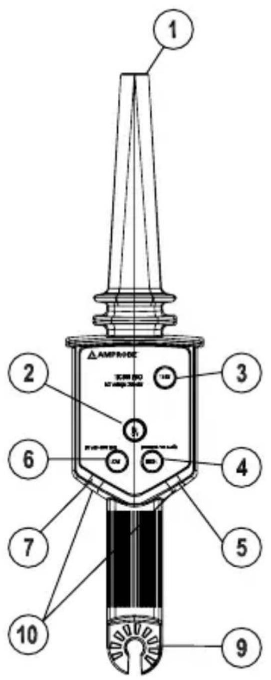
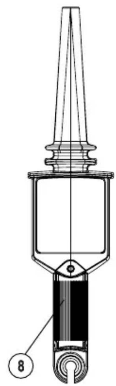
1) Voltage sensor
2) ON/OFF Button
3) Circuit TEST button
4) HIGH range switch
5) HIGH range LED
6) LOW range switch
7) LOW range LED
8) Battery compartment
9) HOT STICK attachment point
10) Detection Blue LED indicators
CONTENTS
SYMBOLS 2
UNPACKING AND INSPECTION 3
INTRODUCTION 4
Features 4
OPERATION 5
ON/OFFButton 5
TESTButton 5
Voltage Detection 6
LOW Range. 6
HIGH Range 6
Locate breaks in insulated wire & heating elements..... 7
Check Outlets and Switches 8
MAINTENANCE AND REPAIR 9
Cleaning. 9
Battery Replacement 9
SPECIFICATIONS 10
Sensitivity: LOW Voltage 11
Sensitivity: HIGH Voltage 11
SYMBOLS
| ! | Refer to the manual |
| 4 | Caution Dangerous Voltage |
| Double insulated | |
| United States Department of Labor MSHA Mine Safety and Health Administration | In compliance with the United States Department Of Labor Mine Safety and Health Administration |
| Conforms to relevant Australian standards. | |
| Conforms to relevant South Korean EMC standards. | |
| Do not dispose of this product as unsorted municipal waste. |
For Use By Trained Personnel Only
Anyone using this instrument should be knowledgeable and trained about the risks involved with measuring medium and high voltage, especially in an industrial setting, and the importance of taking safety precautions and of testing the instrument before and after using it to ensure that it is in good working condition.
WARNING and PRECAUTIONS
- Use extreme caution when testing live electrical circuits due to risk of injury from electrical shock.
- Do not exceed the maximum overload limits (see specifications) or the limits marked on the instrument itself. Never test voltage more than 122kV AC RMS.
- When using the HIGH range, the TIC 410A HOT STICK or equivalent extension pole MUST be used.
- Comply with local and national safety requirements.
-
Use proper protective equipment as required by local and national authorities.
-
Observe the proper safety precautions when working with voltages above 33 VAC RMS to avoid electrical shock hazard.
- Before and after hazardous voltage measurements, test the TIC 300 PRO by pressing the TEST button and/or on a known source such as line voltage to determine proper operation.
- Never ground yourself when taking measurements. Do not touch exposed circuit elements.
- Do not operate the instrument in an explosive atmosphere.
- Do not expose this product to rain or moisture. This increases the risk of fire or electric shock.
- Do not rely on the TIC 300 PRO for testing shielded wire.
- Do not let the unit make contact with a live line with voltage higher than 20kV .
- Three phase feeder cables with conductors close to each other may self-cancel the electric field and will not be detected by the TIC 300 PRO tracer. Verify that the phase conductors are separated by at least 15 in (38.1 cm) before testing for AC voltage.
UNPACKING AND INSPECTION
Your shipping carton should include:
1 TIC 300 PRO
1 9 V Alkaline Battery
1 User Manual
1 Carrying Case
If any of the items are damaged or missing, return the complete package to the place of purchase for an exchange.
INTRODUCTION
The TIC 300 PRO safely checks for the presence of AC voltage without making any disconnection in cables, wall sockets, fuses, circuit breakers, junction boxes, etc. No current flow is needed for correct operation.
Rugged and reliable for utility, industrial and mine safety applications, the TIC 300 PRO warns against dangerous voltages in low and medium voltage applications up to 122KV without contacting the energized conductor.
Features
- Utility tool for checking transmission lines, power distribution equipment, down power lines, fuses, and load break connectors
- Lower voltage setting for checking voltage presence in breaker panels, breakers, power outlets and wiring
- Verifies presence of voltage from 30 VAC to 122,000 VAC (122 kV)
- Non-contact AC voltage detection
- Visual and audible voltage indication
- Self-test for verifying that the tester is working properly
- Ergonomic design with a convenient handle
- Drop proof up to 6 ft (1.83 m)
Use with the Hot Stick 410A when voltage exceeds 1500 V
OPERATION
ON/OFF Button
When the TIC 300 PRO is activated, the blue LEDs and beeper will pulse at a slow rate about twice a second. The red LED of the range (HIGH) will turn ON.
TEST Button
The TEST button should be used prior to testing actual power circuits. The TEST function will cause the blue LEDs and beeper of the range selected (LOW or HIGH) to pulse at a fast rate.
OSHA listed clearance distances for working with voltage. National or local requirements may be different.
| Line voltage (kV) | Phase to ground Phase | phase to phase | ||
| phase to phase (ft-in) (m) (ft-in) (m) | ||||
| 0.03 to 1.0 Note1 | Note1 | Note1 | Note1 | |
| 1.1 to 15.0 2-1 0.64 2-2 0.66 | ||||
| 15.1 to 36.0 2-4 0.72 2-7 0.77 | ||||
| 36.1 to 46.0 2-7 0.77 2-10 0.77 | ||||
| 46.1 to 72.5 3-0 0.90 3-6 1.05 | ||||
| 72.6 to 121 3-2 0.95 4-3 1.29 | ||||
Note1 - No contact necessary
Caution: If a three phase circuit is being checked and one phase is open, the voltage from another phase maybe detected and will give a faulty indication. Always make sure that the phase cables are separated by at least 20 in (50.8 cm).
Voltage Detection
LOW Range
- Push the ON/OFF push button to turn the unit ON.
- The high voltage detection circuit is activated. A beep will sound and the blue LEDs will flash twice per second.
- Push the LOW range push button. The unit is ready for low voltage detection.
- Place the probe tip of the TIC 300 PRO near, but not touching, a low (<1000 V) voltage line (Fig. 1).
- If voltage is present, the blue LEDs will blink and the beeper will sound at an increased rate. Continuous visual (blue LEDs) and audible indicators will increase when the probe tip makes contact with or is very close to the voltage line.
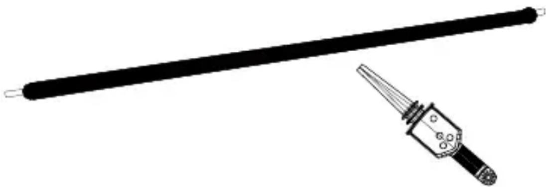
Fig. 1 Voltage detection in a line
HIGH Range (HOT STICK must be used) (See Fig. 2)
- Push the ON/OFF push button to turn the unit ON.
- The high voltage detection circuit is activated. A beep will sound and the blue LEDs will flash twice per second.
-
Approach the probe tip near, but not touching, a high voltage (>1500V and < 122kV) conductor.
-
If voltage is present, the blue LEDs will blink and the beeper will sound at an increased rate. Continuous visual (blue LEDs) and audible indicators will increase when the probe tip makes contact with or is very close to the high voltage line.
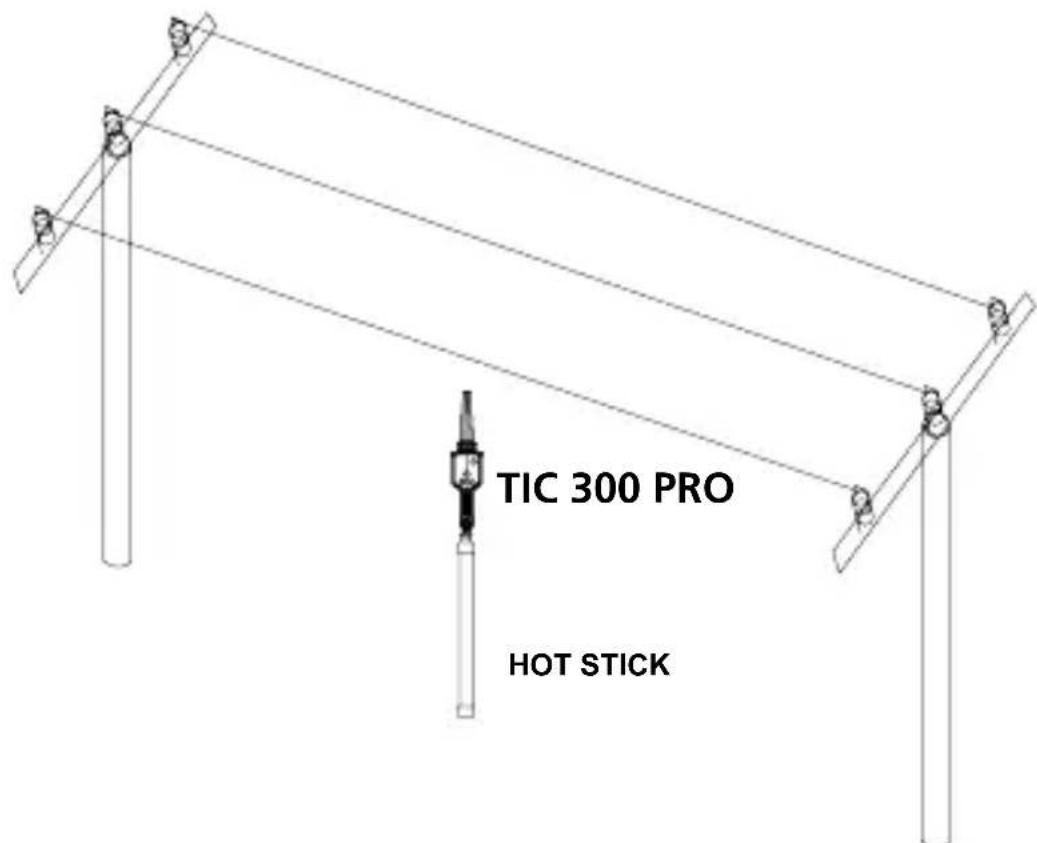
Fig. 2 Voltage detection in transmission lines
Locate breaks in insulated wire and heating elements (See Fig. 3)
-
Push the ON/OFF push button to turn the unit on.
-
Push the LOW range push button.
-
Make sure the wire or the heating element is energized.
-
Place the tip of the probe near the wire and start tracing along it. When the fast or continuous beeping stops, the point of the break or "open" is indicated.
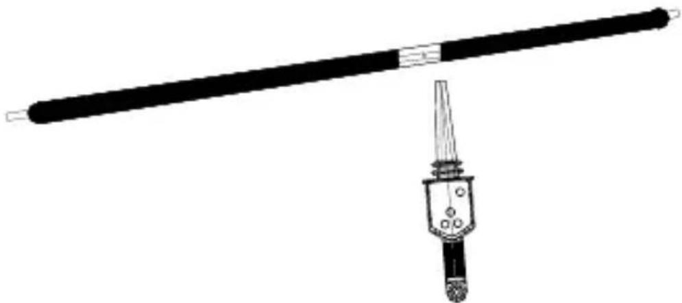
Fig. 3 Finding a break/open
Check Outlets and Switches (See Figs. 4 & 5)
- Push the ON/OFF push button to turn the unit on.
- Push the LOW range push button.
- Place the probe tip of the TIC 300 PRO against the hot prong of an outlet or switch contact.
- Increased beeping indicates higher voltage presence.
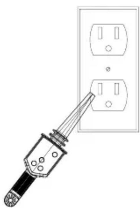
Fig. 4
Detecting voltage in an outlet (Note: disconnect all power cords from the outlet before testing)
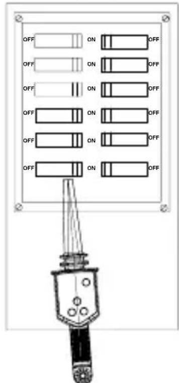
Fig. 5
Finding a breaker
If there appears to be a malfunction during the operation of the voltage detector, the following steps should be performed in order to isolate the cause of the problem:
- Check the battery.
- Review the operating instructions for possible mistakes in operating procedure.
Except for the replacement of the battery, repair of the voltage detector should be performed only by a Factory Authorized Service Center or by other qualified instrument service personnel.
Cleaning
The front panel and case can be cleaned with a mild solution of detergent and water. Apply sparingly with a soft cloth and allow to dry completely before using. Do not use aromatic hydrocarbons or chlorinated solvents for cleaning.
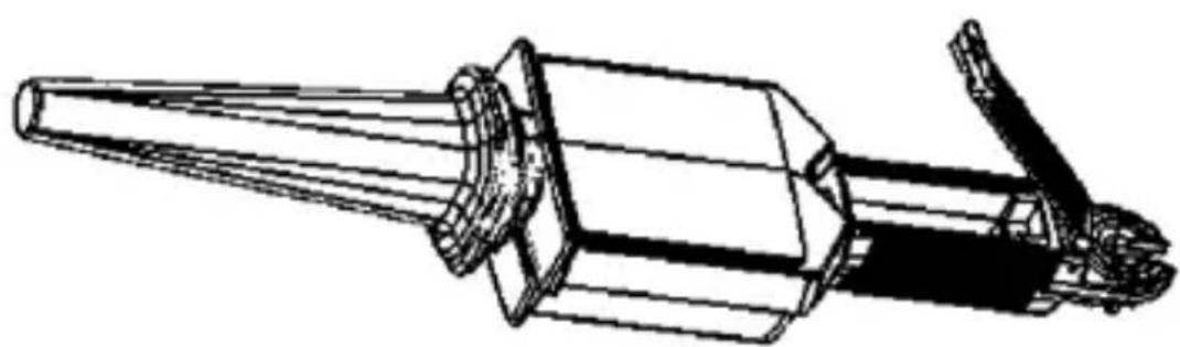
Battery Replacement
Use a Phillips blade screwdriver to remove the battery hatch screw. Lift the hatch. Remove the battery and replace it with a 9 V alkaline battery. Make sure the seal is in place. Close the battery hatch and replace the screw.
SPECIFICATIONS
| Operating voltage | LOW Range: 30 to 1500 VAC HIGH Range: 1500 VAC to 122 kVAC |
| Operating Temperature | 0°C to +52°C (32°F to +125°F); RH < 90% |
| Storage Temperature | 0°C to +52°C (32°F to +125°F) battery removed |
| Environment < 20 | 00 m (1.24 mi), outdoor operation |
| Power 9 V alkaline | battery |
| Power Consumption | OFF: 60 uA Low Detection mode: 39 mA High Detection mode: 39 mA |
| Duty Cycle Continuous | |
| Frequency Response | 50/60 Hz |
| Response Time Instantaneous | |
| Dimensions 345(L) x 75(W) x 47(H) mm (13.5 x 3.0 x 1.8 in) | |
| Weight 243 g (0.5 lb) | |
| Optional Accessory | TIC 410A Hot Stick |
| Electromagnetic Compatibility (EMC) | EN 61326-1 Korea (KCC): Class A Equipment (Industrial Broadcasting & Communication Equipment) [1] [1] This product meets requirements for industrial (Class A) electromagnetic wave equipment and the seller or user should take notice of it. This equipment is intended for use in business environments and is not to be used in homes. |
Sensitivity: LOW Voltage
Hold the TIC 300 PRO when making the detection range measurement for LOW voltage range.
| Voltage (Phase to neutral with 890K Ohm load) | Detection Range (From the TIP of probe to the target line) |
| Average | |
| 30 V 3.8 cm (1.5 in) | |
| 75 V 16.5 cm (6.5 in) | |
| 100 V 21.6 cm (8.5 in) | |
| 120 V 25.4 cm (10 in) | |
| 220 V 33 cm (1 ft) | 1 in) |
| 500 V 48.3 cm (1 ft 7 in) | |
| 1000 V 86.4 cm (2 ft 10 in) |
Sensitivity: HIGH Voltage
The TIC 410A Hot Stick must be used when making detection range measurement for HIGH voltage range.
| Voltage (Open Phase with no load) | Detection Range (From the TIP of probe to the target line) |
| Average | |
| 1.5 kV 12.7 mm (0.5 in) | |
| 2.0 kV 25.4 mm (1 in) | |
| 4.0 kV 5.1 cm (2 in) | |
| 10.0 kV 20.3 cm (8 in) | |
| 15.0 kV 35.6 cm (1 ft 2 in) | |
| 20.0 kV 50.8 cm (1 ft 8 in) | |
| 25.0 kV 66 cm (2 ft 2 in) |
TIC 300 PRO
Amprobe Test Tools Amprobe Test Tools
Everett, WA 98203 Mississauga, ON L4Z 1X9
Tel.: 877-AMPROBE (267-7623) Tel.: 905-890-7600
Amprobe Test Tools Amprobe Test Tools
Everett, WA 98203 Mississauga, ON L4Z 1X9
Tel.: 877-AMPROBE (267-7623) Tel.: 905-890-7600
Visit amprobe.com for
- Catalog
Application notes
Product specifications - User manuals
Amprobe®
amprobe.com
Division of Fluke Corp.
6920 Seaway Blvd.
M/S 143F
Everett, WA 98203 USA
Tel: 877-AMPROBE (267-7623)
Beha-Amprobe
beha-amprobe.com
c/o Fluke Europe BV
Science Park
Eindhoven 5110
NL-5692 EC Son
Tel.: +49 (0) 7684 8009 - 0

Please
Recycle



- Limited Warranty and Limitation of Liability
- Repair
- In-Warranty Repairs and Replacement – All Countries
- Non-Warranty Repairs and Replacement - US and Canada
- Non-Warranty Repairs and Replacement - Europe
- CONTENTS
- SYMBOLS
- For Use By Trained Personnel Only
- WARNING and PRECAUTIONS
- UNPACKING AND INSPECTION
- INTRODUCTION
- Features
- OPERATION
- ON/OFF Button
- TEST Button
- OSHA listed clearance distances for working with voltage. National or local requirements may be different.
- Voltage Detection
- LOW Range
- HIGH Range (HOT STICK must be used) (See Fig. 2)
- Locate breaks in insulated wire and heating elements (See Fig. 3)
- Check Outlets and Switches (See Figs. 4 & 5)
- Cleaning
- Battery Replacement
- SPECIFICATIONS
- Sensitivity: LOW Voltage
- Sensitivity: HIGH Voltage
- TIC 300 PRO
- Visit amprobe.com for
- Amprobe®
- Beha-Amprobe
Brand : Amprobe
Model : TIC300PRO
Category : Detector