
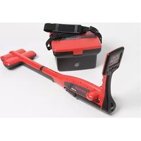
AT-3500 - Detector Amprobe - Free user manual and instructions
Find the device manual for free AT-3500 Amprobe in PDF.


| Product Type | Underground conduit/cable detector |
| Brand | Amprobe |
| Model | AT-3500 |
| Receiver R-3500 - Dimensions (L x H x D) | 99 x 660 x 252 mm |
| Receiver R-3500 - Weight | 2.5 kg |
| Transmitter T-3500 - Dimensions (L x H x D) | 260 x 255 x 140 mm |
| Transmitter T-3500 - Weight | 1.7 kg |
| Receiver power supply | 10 batteries 1.5 V AA (Mignon) - duration 40 h |
| Transmitter power supply | 6 batteries 1.5 V D (Mono) - duration 40 h |
| Main functions | Locating metallic lines, depth measurement (0.1 to 5 m), modes Radio, Power, Transmitter |
| Coupling modes | Direct, inductive, via optional SC-3500 clamp |
| Reception frequencies | Radio 15-23 kHz, Power 50/60 Hz, Transmitter 32.768 kHz |
| Depth measurement accuracy (Transmitter mode) | ±5 % (depth > 5 m) / ±20 % (depth < 5 m) |
| Receiver protection rating | IP67 (lower part) / IP56 (upper part) |
| Transmitter protection rating | IP56 |
| Operating temperature range | -20 °C to +55 °C |
| Maintenance and cleaning | Clean with a soft, dry cloth. Replace batteries as indicated. |
| Safety | Use only the supplied accessories. Do not expose to strong impacts. |
| Spare parts and repairability | Replaceable ground protection device. Repairs by Amprobe authorized service center. |
| Warranty | 1 year against defects in materials and workmanship. |
| Box contents | 1 receiver R-3500, 1 transmitter T-3500, 2 measurement cables, 2 alligator clips, 1 ground rod, 10 AA batteries, 6 D batteries, 1 nylon carry case |
Frequently Asked Questions - AT-3500 Amprobe
User questions about AT-3500 Amprobe
0 question about this device. Answer the ones you know or ask your own.
Ask a new question about this device
Download the instructions for your Detector in PDF format for free! Find your manual AT-3500 - Amprobe and take your electronic device back in hand. On this page are published all the documents necessary for the use of your device. AT-3500 by Amprobe.
USER MANUAL AT-3500 Amprobe
Underground Cable/Pipe Locator System
Users Manual
Mode d'emploi•
Bedienungshandbuch•
Manuale d'Uso•
Manual de uso•
Användarhandbok•

AT-3500
Underground Cable/Pipe Locator System
Users Manual
Limited Warranty and Limitation of Liability
Your Amprobe product will be free from defects in material and workmanship for 1 year from the date of purchase. This warranty does not cover fuses, disposable batteries or damage from accident, neglect, misuse, alteration, contamination, or abnormal conditions of operation or handling. Amprobe's warranty obligation is limited, at Amprobe's option, to refund of the purchase price, free of charge repair, or replacement of a defective product. Resellers are not authorized to extend any other warranty on Amprobe's behalf. To obtain service during the warranty period, return the product with proof of purchase to an authorized Amprobe Test Tools Service Center or to an Amprobe dealer or distributor. See Repair Section for details. This warranty is your only remedy. All other warranties - whether express, implied or statutory - including implied warranties of fitness for a particular purpose or merchantability, are hereby excluded. Neither Amprobe nor its parent company or affiliates shall be liable for any special, indirect, incidental or consequential damages or losses, arising from any cause or theory. Since some states or countries do not allow the exclusion or limitation of an implied warranty or of incidental or consequential damages, this limitation of liability may not apply to you.
Repair
All test tools returned for warranty or non-warranty repair or for calibration should be accompanied by the following: your name, company's name, address, telephone number, and proof of purchase. Additionally, please include a brief description of the problem or the service requested and include the test leads with the meter. Non-warranty repair or replacement charges should be remitted in the form of a check, a money order, credit card with expiration date, or a purchase order made payable to Amprobe® Test Tools.
In-Warranty Repairs and Replacement – All Countries
Please read the warranty statement and check your battery before requesting repair. During the warranty period any defective test tool can be returned to your Amprobe® Test Tools distributor for an exchange for the same or like product. Please check the "Where to Buy" section on www.amprobe.com for a list of distributors near you. Additionally, in the United States and Canada In-Warranty repair and replacement units can also be sent to a Amprobe® Test Tools Service Center (see below for address).
Non-Warranty Repairs and Replacement – US and Canada
Non-warranty repairs in the United States and Canada should be sent to a Amprobe® Test Tools Service Center. Call Amprobe® Test Tools or inquire at your point of purchase for current repair and replacement rates.
In USA In Canada
Amprobe Test Tools Amprobe Test Tools
Everett, WA 98203 Mississauga, ON L4Z 1X9
Tel: 888-993-5853 Tel: 905-890-7600
Fax: 425-446-6390 Fax: 905-890-6866
Non-Warranty Repairs and Replacement – Europe
European non-warranty units can be replaced by your Amprobe® Test Tools distributor for a nominal charge. Please check the "Where to Buy" section on www.amprobe.com for a list of distributors near you.
European Correspondence Address*
Amprobe® Test Tools Europe
Beha-Amprobe GmbH
In den Engematten 14
79286 Glottertal, Germany
Tel.: +49 (0) 7684 8009 - 0
*(Correspondence only – no repair or replacement available from this address. European customers please contact your distributor.)

R-3500 Receiver
① Control Panel with display
② Speaker with Volume control
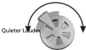
③ Headphone jack (3.5 mm headphone not included)
④ Battery Compartment
⑤ Floor Cap (Removable)

R-3500 Display
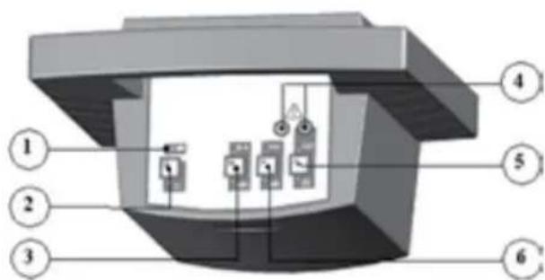
1 Light Sensor: Automatically regulates the brightness of the display
② ON/OFF Switch
③ Display: Provides visual indication of the signal strength, depth measurement, and mode of operation, Battery Status, and menu items.
4 Control1
5 Control2
6 Control3
T-3500 Transmitter
① Battery status indicator: Battery status LED blinks in red when near empty
② ON/OFF Button
③ Signal Type: To switch between continuous and pulsed signal output
4 Input Jacks
⑤ Mode: To switch between inductive and direct signal coupling
6 Signal Strength: To select one of two signal strength levels (0.1W or 0.5W)
CONTENTS
Unpacking And Inspection 5
Introduction....5
Operation 5
Applications and principles of direct coupling....6
Direct Coupling....7
Direct Coupling using the A-3500 Clamp....7
Inductive Coupling....7
Locating Passive Lines (Radio and Power Modes)....7
Locating unknown cables....7
Depth Measurement....7
Error messages during a depth measurement 8
Technical Specifications 8
Maintenance....9
Changing the battery in the R-3500 receiver....9
Changing the batteries in the T-3500 transmitter 10
Changing the floor cap on the R-3500 receiver....10
UNPACKING AND INSPECTION
Your shipping carton should include:
1 R-3500 Receiver
1 T-3500 Transmitter
2 Measurement Cables
2 Alligator Clips
1 Grounding Rod
10 Battery IEC R6/AA Cell /Migon
6 IEC R20/ D Cell/ Mono
1 Nylon Bag
INTRODUCTION
The AT-3500 underground cable/pipe locator system is designed for the uncomplicated and user-friendly determination of the location, orientation and depth of metallic lines (e.g. cable and pipe lines).
It can be used to probe areas for unknown lines or for locating specific lines.
The AT-3500 is distinguished by the following features:
Robust construction for use in poor weather and in harsh environments
Simple, user-friendly operation concept with a minimum number of controls
Reliable battery status indicator
OPERATION
Decide which mode of operation to use for your application1.
Induction: Transmitter's signal is emitted through the integrated antenna and is thereby inductively coupled with any metallic lines located within a certain radius.
Place the T-3500 transmitter on the site to be searched. Refer to Figs.1, 2.3&4.i.
Direct Connection: Transmitter's signal is directly coupled with a metallic line via the measurement cable which is connected to the jacks on the front panel of the transmitter. Transmitter clamps, alligator clips or power socket adapters (for example) may be used to connect the measurement cable to the lines.
Connect the T-3500 transmitter to the line to be located using the desired method. Refer to Figs 1, 2, 3, & 4i.
T-3500 Transmitter
Push and Hold 2. ON/OFF button to switch on the T-4000
Push 3. Mode: C to select direct coupling or inductive coupling
- Direct coupling
Green LED blinking: good (low-resistance) connection
Alternating red and green LED blinking: sufficient connection
Red LED blinking: poor/no (high-resistance) connection
- Inductive Coupling:
Green LED blinking: induction mode is active
Push 4. Signal Type: M to select Pulsed or Continuous signal
- Pulsed Signal is helpful when there is interference. Easier to distinguish from other signals.
- Continuous Signal is better to be used when taking a depth measurement
Green LED blinking indicates respective signal is on
- Push Signal Strength: P to select low (0.1W) or High(0.5W) output signal strength
- Low output (0.1W) for normal tracing. Battery saving
• High output(0.5W) for long tracing
Green LED blinking indicates respective signal is on
R-3500 Receiver
-
Push and Hold the Control1 button 1
-
Push briefly the ON/OFF button ① while holding control1 button
- Listen for the audible signal before releasing control1
• The display shows the following:

-
Push control3 to select the unit of measurement (meter ??m or ft ?'??')
-
Push Control1 to select normal depth measurement or depth measurement using the mouse
Push10: button to save the setting.
An audible sound is heard•
The display shows the main menu: •

Push Control3 to select the mode of operation11.
Radio for locating cables carrying VLF re-radiated radio signals (No need for T-3500)
Power Grid for locating main power cables that carry electrical current (No need for T-3500)
Transmitter ▶ for locating cables or pipes carrying the signal of the T-3500 transmitter.
Push Control2 twice rapidly to select automatic or manual sensitivity adjustment12.
Automatic sensitivity adjustment:
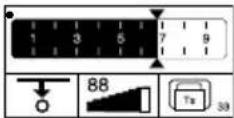
Manual Sensitivity adjustment:

Push control1 to decrease sensitivity adjustmenti.
Push control3 to increase sensitivity adjustmentii.
Push Control2 to start a depth measurement.iii.
Hold the R-3500 receiver in an upright position in front of you as close to the ground as possible. Refer to Fig. 1.13.
- Receiver in line with the conductor Maximum signal strength
- Receiver perpendicular to the conductor minimum signal strength
APPLICATIONS AND PRINCIPLES OF DIRECT COUPLING
- Single-wire cables or pipes (with or without insulation against ground)
The distance between the grounding rod and the ends of the connected lines should be as great as possible because return current tends to flow through the earth into adjacent lines, which could result in their path being followed.

natural_image
Simple electrical circuit diagram showing a multimeter connected to two resistors with wires and ground connections (no text or symbols)- Single-wire cable with metallic screen and ground insulation
Short circuit between internal conductor and screen at the end of the cable with ground at the beginning and end of the cable as well.
Failure to make the connection as shown will result in current cancellation from the internal conductor and the return current in the screen. Under certain circumstances this can prevent the cable from being detected.

natural_image
Simple electrical circuit diagram showing a multimeter connected to two resistors with power supply (no text or symbols)-
Multiple-wire cable (internal conductor connected or disconnected) with metallic screen and grounding insulation Same application as in example 1
-
Metallic conduit (with or without insulation) the grounding rod and the conduit should be spaced as far apart as possible. Under certain circumstances, optimum positioning of the grounding rod may require several attempts.
-
If a return wire is available the spacing of the return wire should correspond to at least 10 times the depth of the line being located.
-
Pair of wires (with or without screen) with short circuit at the end of the cable For twisted cable pair (with a length of lay of the twist greater or equal to the laying depth), the orientation of the cable can be easily determined.
Adjacent lines which are horizontal to each other Minimum of the reception signal
Lines situated on top of each other vertically Maximum of the reception signal
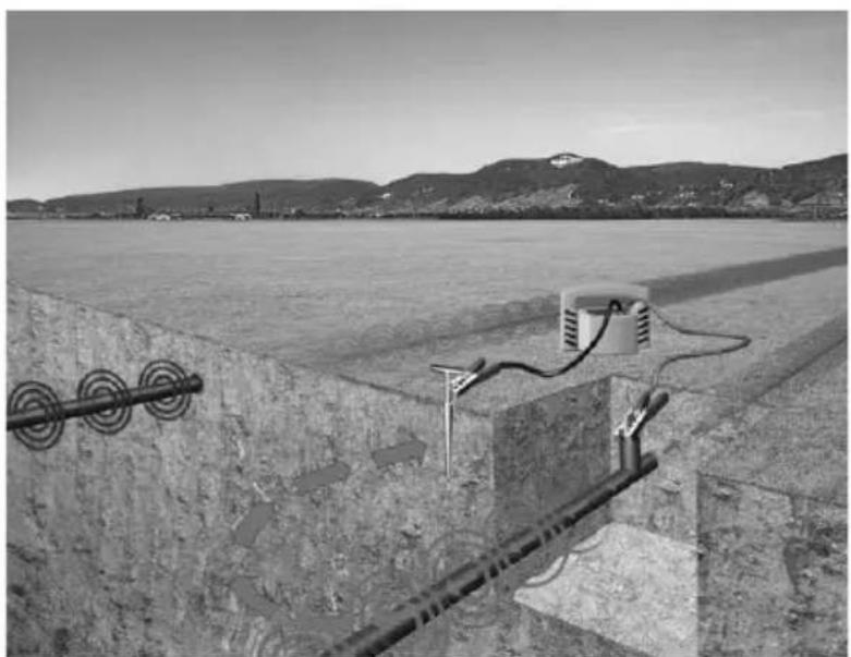
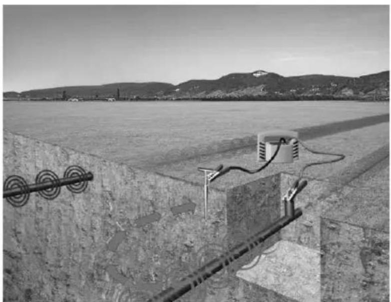
Direct Coupling (Refer to Fig. 2.)
Connect the red test lead of the T-3500 transmitter with the conductor to be traced1.
- Connect the black test lead of the T-3500 transmitter to ground using the grounding rod. Alternatively the black test lead may be clipped to the rim of a valve box or manhole cover.
Switch the T-3500 on3.
Select pulse or continuous signal transmission4.
Switch the R-3500 Receiver on5.
Begin to trace the cable from the point of application about 50-FT (15m) away6.
Move slowly over the cable. Decrease or increase the sensitivity as needed7.
Direct Coupling using the A-3500 Clamp (Refer to Fig. 3.)
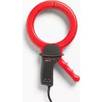
Plug the SC-3500 clamp into the T-3500 transmitter connection socket1.
Place the clamp around the pipe or cable2.
Switch the T-3500 transmitter on3.
Set the T-3500 transmitter to pulse or continuous signal transmission4.
Switch the R-3500 Receiver on5.
Select transmitter 6
Begin to trace the cable from the point of application about 15m away7.
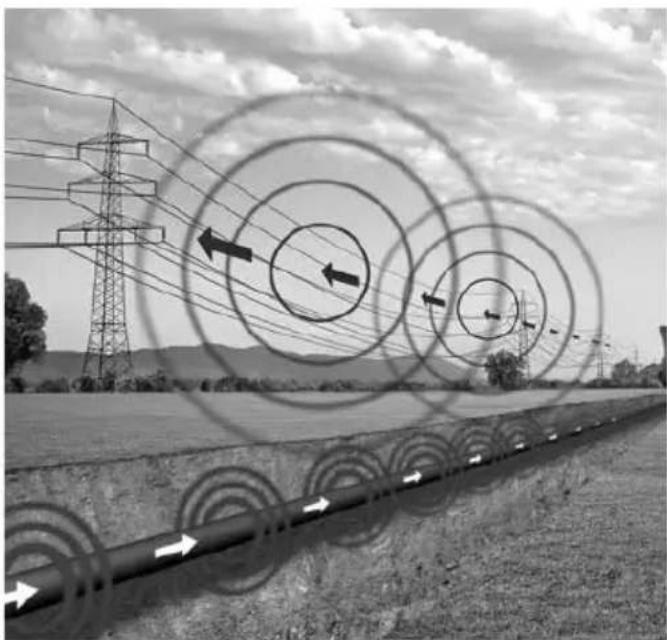
Inductive Coupling (Refer to Fig. 4.)
Position the T-3500 transmitter above the presumed cable1.
Switch on the T-3500 transmitter2.
- Switch on the R-3500 receiver
- Select the appropriate mode. Refer to section: Operation:R-3500
- Begin to trace the line from the transmitter at least 15m away.
- Make sure that a distance of at least 50-FT (15m) is always maintained between the receiver and transmitter in order to prevent the coupling of the transmitter's signal through the air.
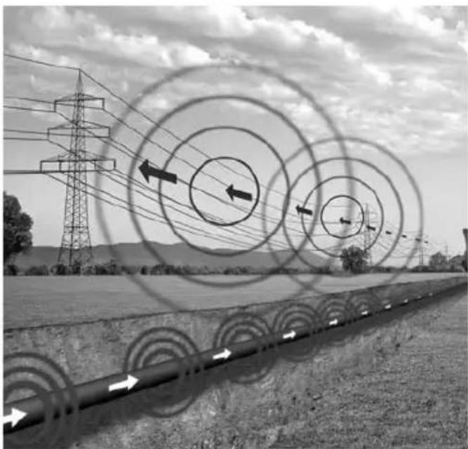
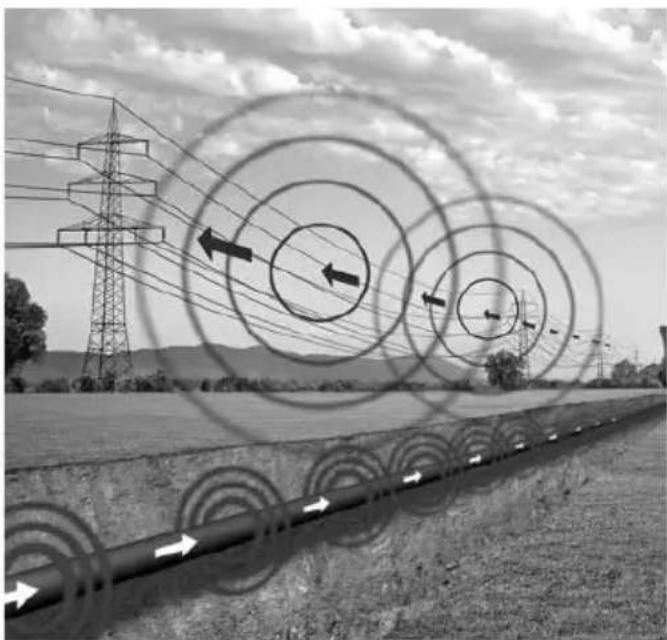
Locating Passive Lines (Radio and Power Modes) (Refer to Fig. 5.)
The R-3500 Receiver can locate passive cables that carry radio signals in the frequency range between 15kHz and 23kHz as well as power signals between the range of 50Hz and 60Hz without the help of the T-3500 Transmitter.
- Turn the R-3500 Receiver on
- Select radio mode or power mode. Refer to section 8 OPERATION.
- Set the sensitivity to maximum
- Sweep the area using a grid pattern as shown below
- Adjust the sensitivity to pinpoint the conductor
- Rotate the R-3500 to find the maximum response
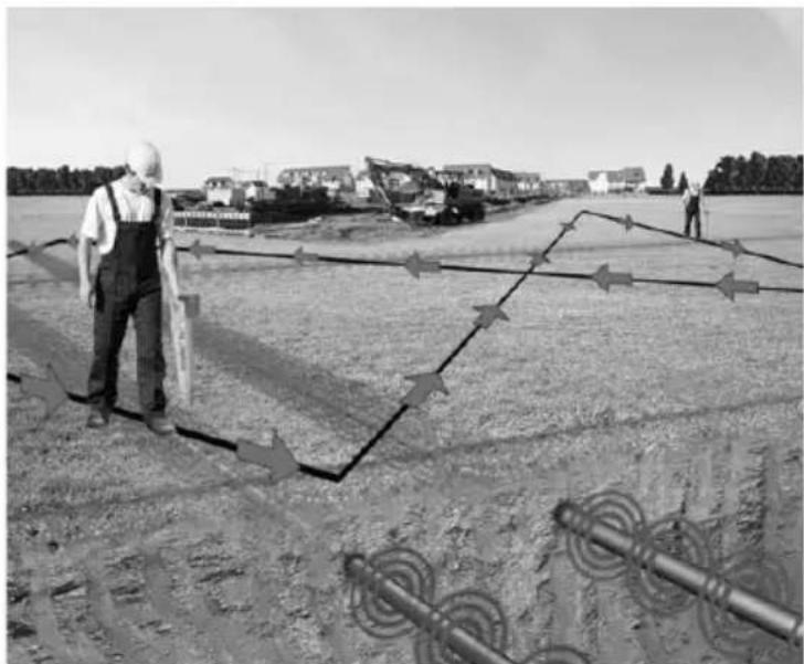
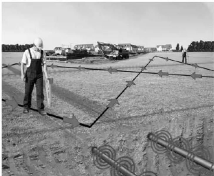
Locating unknown cables (Refer to Fig. 6.)
- Use the T-3500 Transmitter using the inductive mode.
- Use the R-3500 Receiver to sweep the area. Keep the receiver 50-FT (15m) apart from the transmitter.
- Select the desired mode of operation.
Adjust the sensitivity of the R-3500 as needed4.
- When a conductor is located, pinpoint the strongest signal and mark the location
- Repeat steps 1 and 2. Move the transmitter at least 3.3-FT (1m) and 90-degree from the initial position.
- Repeat the process until the right cable is detected.
Depth Measurement (Refer to Fig. 7.)
- Connect the T-3500 transmitter with the cable or the metallic pipe
- Turn the T-3500 transmitter on. Use continuous signal mode for better result
- Turn the R-3500 receiver on and move at least 50-FT (15m) away from the transmitter
- Rotate the R-3500 receiver until the maximum signal strength is detected
- Push control1 to take an automatic depth measurement
- The measurement will display as follow:

- To change the unit of measure, refer to R-3500 mode of operation (section 8).
- For non-metallic pipe, use the M-3000 mouse. Refer to R-3500 receiver mode of operation section 9 to set the receiver accordingly.
For Power and Radio signals, an estimated depth measurement can be taken as follow:9.
Push control3 to select Power or Radio mode
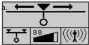
Move to one side of the suspected cable until the following symbol appears:

Mark the spotc.
Move to the other side until the symbol appears againd.
Mark the spot.
Measure the distance between the two spotsf.
Divide the measurement by 2 to find the depth of the cable.g.
ERROR MESSAGES DURING A DEPTH MEASUREMENT
| Symbol Meaning | |
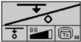 | For of one of the following reasons, the depth could not be measured:The signal received was too weak or too irregular.The receiver was not held steady enough during the measuring process.The receiver was not positioned directly above the line at the beginning of the process. |
 | The depth of the metallic conductor amounts to more than 5 m (16 ft). |
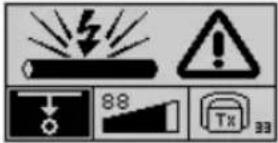 | The depth of the metallic conductor amounts to less than 30 cm (1 ft). Such conductors must be specially marked in order to prevent damage during construction. |
 | The receiver was moved too far to the left or right while making a rough estimate. Move in the opposite direction until the following symbol appears: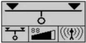 |
TECHNICAL SPECIFICATIONS
R-3500
The following parameters are specified for the R-3500 receiver:
Frequency ranges
• Range 1: radio 15 kHz to 23 kHz
• Range 2: power network 50 Hz / 60 Hz; optionally 100 Hz (can be adjusted by Amprobe service personnel)
• Range 3: transmitter 32.768 kHz
Sensitivity at a depth of 1m
• Range 1: radio >20 μA
• Range 2: power network >7 mA
• Range 3: transmitter >5 μA
Dynamic response range
• Range 1: radio 120 dB
• Range 2: power network 135 dB
• Range 3: transmitter 120 dB
Depth determination
- Depth range
0.1 m ... 5 m (4 in ... 16 ft)
- Resolution 0.1 m
- Accuracy
- Range 1: radio ±20 %
- Range 2: power network ±20 %
- Range 3: transmitter ±5 % (>5m (6-FT)), ±20 % (<5m (15-FT))
Power supply 10 x IEC R6 / AA cell / Mignon
Operating time 40 hours (for intermittent use with alkaline batteries, 20 °C)
Temperature range in accordance with DIN EN 60068-1
• Operation -20 °C to +55 °C
• Storage -30 °C to +70 °C
Weight 2.5 kg, 5.51 lbs.
Dimensions (W x H x D) 99 x 660 x 252 mm, .3.90 x 25.98x 9.92 in
Type of protection in accordance with EN 60529
Dust and water protected IP 67 from the lower edge of the receiver up to the lower edge of the battery compartment, and IP 56 for all parts above this delineation
T-3500
The following parameters are specified for the T-3500 transmitter:
Transmitted power 0.1 W / 0.5 W (switchable)
Frequency 32.768 kHz
Power supply 6 x IEC R20 / D cell / Mono
Operating time 40 hours (for intermittent use with alkaline batteries, 20 °C)
Temperature range in accordance with DIN EN 60068-1
• Operation -20 °C to +55 °C
• Storage -30 °C to +70 °C
Weight 1.7 kg, 3.75 lbs.
Dimensions (W x H x D) 260 x 255 x 140 mm,
Type of protection in accordance with EN 60529
Dust and water protected IP 56
MAINTENANCE
Changing the battery in the R-3500 receiver
The status of the receiver's batteries is checked upon start-up and indicated in the display.
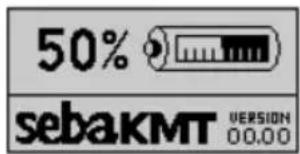
The system regularly checks the battery strength as well. If battery capacity falls below 10 % of the threshold value, an audible warning signal is given and the current status of the batteries is shown in the upper part of the display.

In order to replace the ten 1.5 V mignon (AA) batteries, the battery housing must be removed as described in the following illustrations:

natural_image
Mechanical assembly diagram showing a sliding mechanism with arrows indicating motion (no text or symbols)Changing the batteries in the T-3500 transmitter
The batteries in the transmitter have to be replaced as soon as the red LED battery indicator starts to blink.

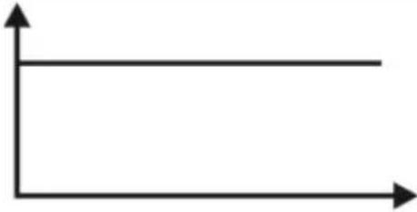
Should this occur while the user is busy locating a line with the receiver, he/she will be informed of the weak batteries via the reception signal:
| Type of signal Normal | signal Signal when batteries are weak | |
 |  | |
 |  |
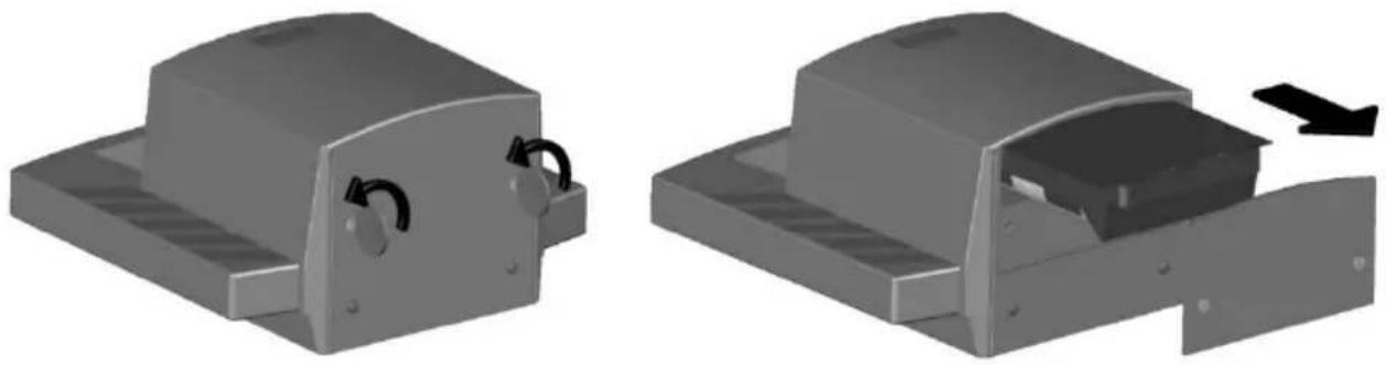
In order to change the six 1.5 V mono (D cell) batteries, both screws on the back of the transmitter must be (e.g. with the aid of a coin) turned through 14 turn (1) and the battery tray must be pulled (2). Please note that all the batteries are fitted in the same direction.
natural_image
Two 3D mechanical component diagrams showing internal components and a directional arrow (no text or symbols)Changing the floor cap on the R-3500 receiver
The plastic floor cap, which prevents the tip of the receiver from being damaged, can be easily replaced with the aid of a pointed object (e.g. screw driver). Replacements can be ordered through the SEBA KMT sales team.

natural_image
Close-up of a screwdriver inserted into a cylindrical device with a black arrow pointing to it (no text or symbols visible)
natural_image
Composite image showing three people standing on a road with floating digital meters and a pipeline below (no text or symbols)Fig. 1

natural_image
Black-and-white photo of a construction site with concrete foundations, utility poles, and a power meter, set against a backdrop of hills and water (no visible text or symbols)Fig. 2

natural_image
Exterior view of a residential courtyard with a small electric vehicle connected to a wall-mounted device (no signage or text visible)Fig. 3

Fig. 4
natural_image
Black-and-white photo of a rural road with power transmission towers and circular traffic signs, no readable text or symbols.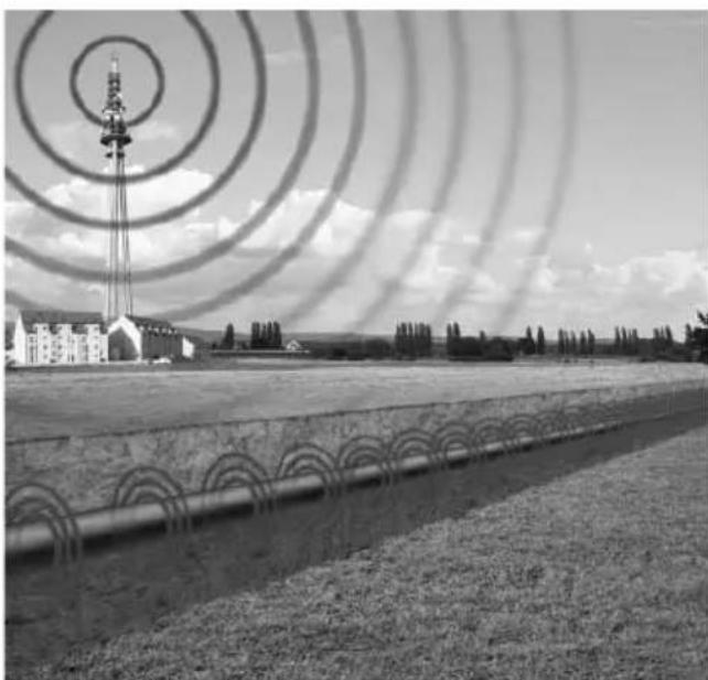
natural_image
Black-and-white photo of a rural landscape with a radio tower, fence, and adjacent buildings under a cloudy sky (no visible text or symbols)Fig. 5
natural_image
Black-and-white photo of workers on a construction site with barbed wire and utility poles, no visible text or symbolsFig. 6

Fig. 7

AT-3500
Amprobe Test Tools Amprobe Test Tools
Everett, WA 98203 Mississauga, ON L4Z 1X9
Tel: 888-993-5853 Tel: 905-890-7600
Fax: 425-446-6390 Fax: 905-890-6866
Récepteur R-3500
Emetteur T-3500
Couplage direct....7
natural_image
Simple electrical circuit diagram showing a voltmeter connected to two parallel conductors with wires and ground connections (no text or symbols)natural_image
Simple electrical circuit diagram showing a multimeter connected to two resistors with power terminals (no text or symbols)Fréquence 32,768 kHz
Alimentation 6 x piles CEI R20 / D / Mono
natural_image
Mechanical assembly diagram showing two components with arrows indicating movement or force (no text or symbols present)natural_image
3D mechanical component diagrams showing two views of a housing with internal slots and mounting brackets (no text or symbols)natural_image
Close-up of a mechanical component with a screwdriver inserted, showing a black arrow pointing to a specific part (no text or symbols visible)
natural_image
Composite image showing three people standing on a road with floating digital meters and a pipeline below (no text or symbols)Fig. 1

natural_image
Black-and-white photo of a construction site with concrete foundations, utility poles, and a power meter, set against a backdrop of hills and water (no visible text or symbols)Fig. 2

natural_image
Exterior view of a residential courtyard with a small electric vehicle connected to a wall-mounted device (no signage or text visible)Fig. 3

Fig. 4
natural_image
Black-and-white photo of a rural road with power transmission towers and circular traffic signs, no readable text or symbols.
natural_image
Black-and-white photo of a rural landscape with a radio tower, fence, and adjacent buildings under a cloudy sky (no visible text or symbols)Fig. 5
natural_image
Black-and-white photo of workers on a construction site with barbed wire and utility poles, no visible text or symbolsFig. 6
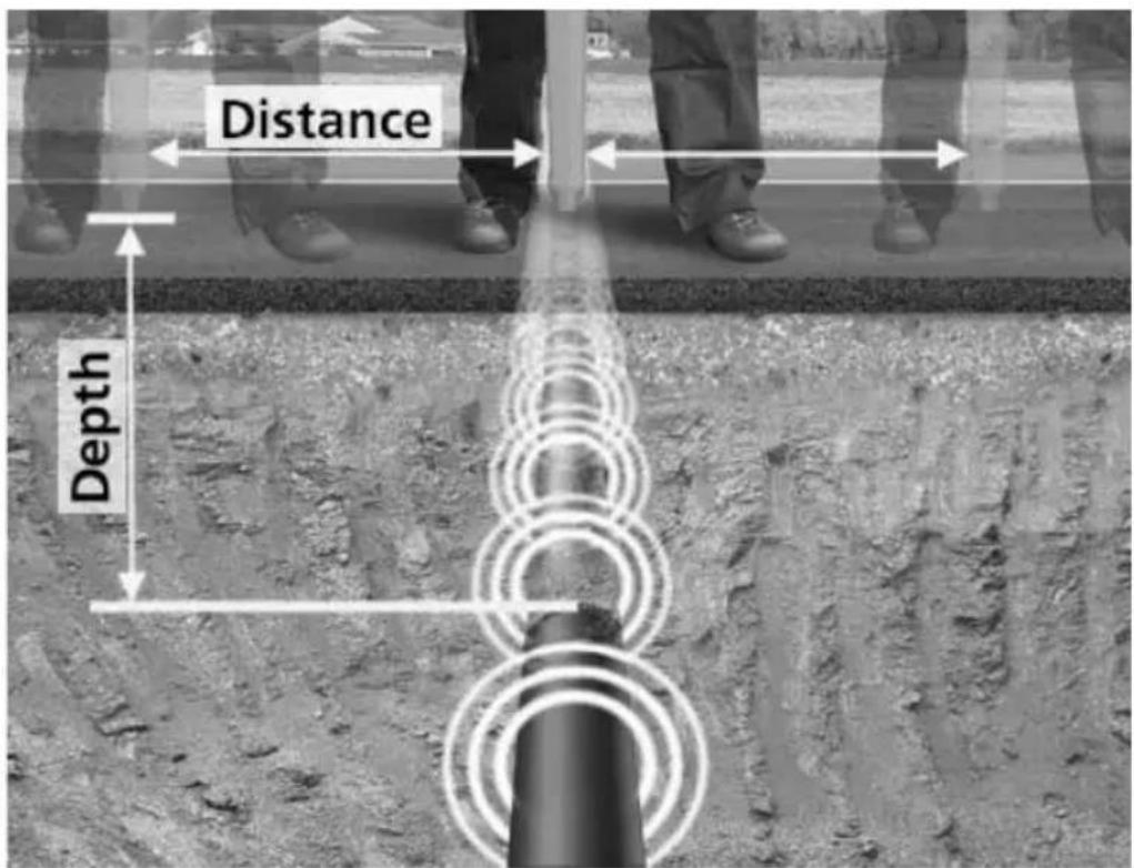
Fig. 7

AT-3500
R-3500 Empfänger
T-3500 Sender
natural_image
Simple electrical circuit diagram showing a multimeter connected to a battery and two parallel conductors (no text or symbols)natural_image
Simple electrical circuit diagram showing a multimeter connected to a resistor and a separate conductor with voltage source (no text or symbols)natural_image
Mechanical assembly diagram showing two components with arrows indicating movement or force direction (no text or symbols present)natural_image
Two 3D mechanical component diagrams showing internal mechanisms with arrows indicating movement (no text or symbols)natural_image
Close-up of a mechanical component with a black arrow pointing to a tool, no visible text or symbols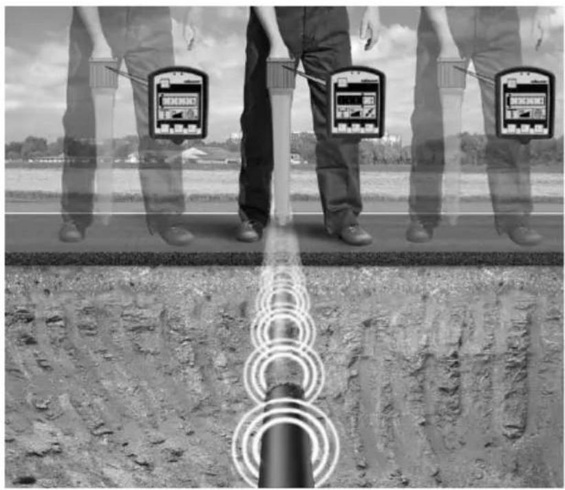
natural_image
Black-and-white composite image showing a person standing on a road with overlaid sensor devices and a close-up of a pipeline (no text or symbols)Abb. 1
natural_image
Black-and-white photo of a construction site with concrete foundations, utility poles, and a power meter, set against a backdrop of hills and water (no visible text or symbols)Abb. 2

natural_image
Exterior view of a residential courtyard with a small electric vehicle connected to a wall-mounted device (no signage or text visible)Abb. 3

Abb. 4
natural_image
Black-and-white photo of a rural road with power transmission towers and circular traffic signs, no readable text or symbols.
natural_image
Black-and-white photo of a rural landscape with a radio tower, fence, and adjacent buildings under a cloudy sky (no visible text or symbols)Abb. 5

natural_image
Construction site with workers and a pipeline, no visible text or symbolsAbb. 6

Abb. 7

AT-3500
Amprobe Test Tools Amprobe Test Tools
Everett, WA 98203 Mississauga, ON L4Z 1X9
Tel: 888-993-5853 Tel: 905-890-7600
Fax: 425-446-6390 Fax: 905-890-6866
Non-Warranty Repairs and Replacement – Europe
Ricevitore R-3500
natural_image
Simple electrical circuit diagram showing a voltmeter connected to two parallel conductors with wires and ground connections (no text or symbols)natural_image
Simple electrical circuit diagram showing a voltmeter connected to two parallel conductors with wires and ground connections (no text or symbols)natural_image
Mechanical assembly diagram showing two components with arrows indicating movement or force (no text or symbols present)natural_image
Two 3D mechanical component diagrams showing internal mechanisms with arrows indicating movement (no text or symbols)natural_image
Close-up of a screwdriver inserted into a cylindrical device with a black arrow pointing to the component (no text or symbols visible)
natural_image
Composite image showing three people standing on a road with floating digital meters and a pipeline below (no text or symbols)Fig. 1
natural_image
Black-and-white photo of a construction site with concrete foundations, utility poles, and a power meter, set against a backdrop of hills and water (no visible text or symbols)Fig. 2

natural_image
Exterior view of a residential courtyard with a small electric vehicle connected to a wall-mounted device (no signage or text visible)Fig. 3

Fig. 4

natural_image
Black-and-white photo of a rural road with power transmission towers and circular traffic signs, no readable text or symbols.
natural_image
Black-and-white photo of a rural landscape with a radio tower, fence, and adjacent buildings under a cloudy sky (no visible text or symbols)Fig. 5

natural_image
Black-and-white photo of a construction site with workers, a fence, and utility poles (no visible text or symbols)Fig. 6

Fig. 7

AT-3500
Amprobe Test Tools Amprobe Test Tools
Everett, WA 98203 Mississauga, ON L4Z 1X9
Tel: 888-993-5853 Tel: 905-890-7600
Fax: 425-446-6390 Fax: 905-890-6866
Receptor R-3500
Transmisor T-3500
natural_image
Simple electrical circuit diagram showing a voltmeter connected to two parallel conductors with wires and ground connections (no text or symbols)natural_image
Simple electrical circuit diagram showing a voltmeter connected to two parallel conductors with wires and ground connections (no text or symbols)natural_image
Mechanical assembly diagram showing two components with arrows indicating movement or force (no text or symbols present)natural_image
Two 3D mechanical component diagrams showing internal components and a black arrow indicating a process (no text or symbols present)natural_image
Close-up of a mechanical component with a black arrow pointing to a tool, no visible text or symbols
natural_image
Black-and-white composite image showing a person standing on a road with overlaid sensor devices and a close-up of a pipeline (no text or symbols)Fig. 1

natural_image
Black-and-white photo of a construction site with concrete foundations, utility poles, and a power meter, set against a backdrop of hills and water (no visible text or symbols)Fig. 2

natural_image
Exterior view of a residential courtyard with a small electric vehicle connected to a wall-mounted device (no signage or text visible)Fig. 3

Fig. 4

natural_image
Black-and-white photo of a rural road with power transmission towers and circular traffic signs, no readable text or symbols.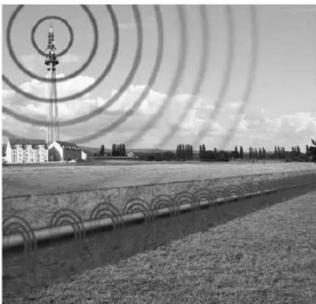
natural_image
Black-and-white photo of a rural landscape with a radio tower, fence, and adjacent buildings under a cloudy sky (no visible text or symbols)Fig. 5

natural_image
Black-and-white photo of workers on a construction site with barbed wire and utility poles, no visible text or symbolsFig. 6
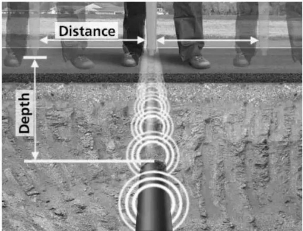
Fig. 7

AT-3500
© 2009 Amprobe Test Tools.
Med ensamrätt.
Amprobe Test Tools Amprobe Test Tools
Everett, WA 98203 Mississauga, ON L4Z 1X9
Tel: 888-993-5853 Tel: 905-890-7600
Fax: 425-446-6390 Fax: 905-890-6866
R-3500-mottagaren
T-3500-sändaren
natural_image
Simple electrical circuit diagram showing a multimeter connected to two resistors with power terminals (no text or symbols)natural_image
Simple electrical circuit diagram showing a voltmeter connected to two parallel conductors with wires and ground connections (no text or symbols)natural_image
Mechanical assembly diagram showing two components with arrows indicating movement or force (no text or symbols present)natural_image
Two 3D mechanical component diagrams showing internal mechanisms with arrows indicating movement (no text or symbols)natural_image
Close-up of a screwdriver inserted into a cylindrical device with a black arrow pointing to it (no text or symbols visible)
natural_image
Composite image showing three people standing on a road with floating digital meters and a pipeline below (no text or symbols)Fig. 1

natural_image
Black-and-white photo of a construction site with concrete foundations, utility poles, and a power meter, set against a backdrop of hills and water (no visible text or symbols)Fig. 2

natural_image
Exterior view of a residential courtyard with a small electric vehicle connected to a wall-mounted device (no signage or text visible)Fig. 3

Fig. 4

natural_image
Black-and-white photo of a rural road with power transmission towers and circular traffic signs, no readable text or symbols.
natural_image
Black-and-white photo of a rural landscape with a radio tower and concentric rings, no visible text or symbols.Fig. 5

natural_image
Black-and-white photo of workers on a construction site with barbed wire and utility poles, no visible text or symbolsFig. 6
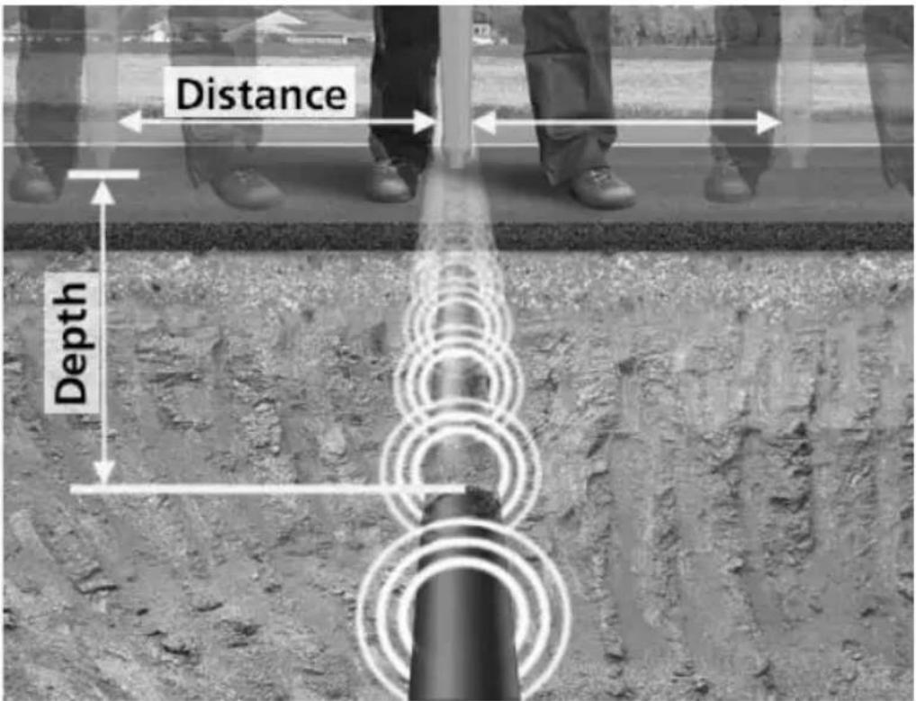
Fig. 7
Visit www.Amprobe.com for
Catalog•
Application notes•
Product specifications•
User manuals•



- Users Manual
- AT-3500
- Limited Warranty and Limitation of Liability
- Repair
- In-Warranty Repairs and Replacement – All Countries
- Non-Warranty Repairs and Replacement – US and Canada
- Non-Warranty Repairs and Replacement – Europe
- CONTENTS
- UNPACKING AND INSPECTION
- INTRODUCTION
- OPERATION
- T-3500 Transmitter
- R-3500 Receiver
- APPLICATIONS AND PRINCIPLES OF DIRECT COUPLING
- Direct Coupling (Refer to Fig. 2.)
- Direct Coupling using the A-3500 Clamp (Refer to Fig. 3.)
- Inductive Coupling (Refer to Fig. 4.)
- Locating Passive Lines (Radio and Power Modes) (Refer to Fig. 5.)
- Locating unknown cables (Refer to Fig. 6.)
- Depth Measurement (Refer to Fig. 7.)
- TECHNICAL SPECIFICATIONS
- R-3500
- T-3500
- MAINTENANCE
- Changing the floor cap on the R-3500 receiver
Brand : Amprobe
Model : AT-3500
Category : Detector