
RS3PRO - Measuring equipment Amprobe - Free user manual and instructions
Find the device manual for free RS3PRO Amprobe in PDF.
| Product type | Analog clamp meter |
| Brand | Amprobe |
| Model | RS3PRO |
| Measurement category | CAT IV 600 V |
| Dimensions (L x W x H) | 243 x 102 x 41 mm |
| Weight | 0,474 kg |
| Jaw opening | 41 mm max |
| Power supply | Battery 1.5 V AAA (ANSI/NEDA-24A, IEC LR03) |
| Measurement functions | AC voltage (600 V), AC current (600/1000 A), resistance (1 kΩ), continuity |
| Display | Mechanical needle with lock |
| Accuracy | ±3 % of full scale |
| Input impedance | 1,5 MΩ |
| Overload protection | 600 V AC rms (voltage), fuse F 0.5 A / 1000 V (ohms) |
| Operating temperature | -15 °C to 50 °C |
| Storage temperature | -20 °C to 60 °C |
| Humidity | < 80 % RH |
| Maximum altitude | 2000 m |
| Double insulation | Yes |
| Compliance | EN61010-1, EN61010-2-032, CE, cULus |
| Package contents | Clamp, test leads, AAA battery, F 0.5 A fuse, instruction manual, carrying case |
| Maintenance | Cleaning with mild water/detergent solution; replace battery and fuse as indicated |
| Repairability | Repair by authorized center; spare parts available |
| Warranty | 1 year against material and workmanship defects |
Frequently Asked Questions - RS3PRO Amprobe
User questions about RS3PRO Amprobe
0 question about this device. Answer the ones you know or ask your own.
Ask a new question about this device
Download the instructions for your Measuring equipment in PDF format for free! Find your manual RS3PRO - Amprobe and take your electronic device back in hand. On this page are published all the documents necessary for the use of your device. RS3PRO by Amprobe.
USER MANUAL RS3PRO Amprobe
Limited Warranty and Limitation of Liability
Your Amprobe product will be free from defects in material and workmanship for 1 year from the date of purchase. This warranty does not cover fuses, disposable batteries or damage from accident, neglect, misuse, alteration, contamination, or abnormal conditions of operation or handling. Amprobe's warranty obligation is limited, at Amprobe's option, to refund of the purchase price, free of charge repair, or replacement of a defective product. Resellers are not authorized to extend any other warranty on Amprobe's behalf. To obtain service during the warranty period, return the product with proof of purchase to an authorized Amprobe Test Tools Service Center or to an Amprobe dealer or distributor. See Repair Section for details. This warranty is your only remedy. All other warranties - whether express, implied or statutory - including implied warranties of fitness for a particular purpose or merchantability, are hereby excluded. Neither Amprobe nor its parent company or affiliates shall be liable for any special, indirect, incidental or consequential damages or losses, arising from any cause or theory. Since some states or countries do not allow the exclusion or limitation of an implied warranty or of incidental or consequential damages, this limitation of liability may not apply to you.
Repair
All test tools returned for warranty or non-warranty repair or for calibration should be accompanied by the following: your name, company's name, address, telephone number, and proof of purchase. Additionally, please include a brief description of the problem or the service requested and include the test leads with the meter. Non-warranty repair or replacement charges should be remitted in the form of a check, a money order, credit card with expiration date, or a purchase order made payable to Amprobe® Test Tools.
In-Warranty Repairs and Replacement - All Countries
Please read the warranty statement and check your battery before requesting repair. During the warranty period any defective test tool can be returned to your Amprobe® Test Tools distributor for an exchange for the same or like product. Please check the "Where to Buy" section on www.amprobe.com for a list of distributors near you. Additionally, in the United States and Canada In-Warranty repair and replacement units can also be sent to a Amprobe® Test Tools Service Center (see below for address).
Non-Warranty Repairs and Replacement - US and Canada
Non-warranty repairs in the United States and Canada should be sent to a Amprobe® Test Tools Service Center. Call Amprobe® Test Tools or inquire at your point of purchase for current repair and replacement rates.
In USA In Canada
Amprobe Test Tools Amprobe Test Tools
Everett, WA 98203 Mississauga, ON L4Z 1X9
Tel: 888-993-5853 Tel: 905-890-7600
Fax: 425-446-6390 Fax: 905-890-6866
Non-Warranty Repairs and Replacement - Europe
European non-warranty units can be replaced by your Amprobe® Test Tools distributor for a nominal charge. Please check the "Where to Buy" section on www.amprobe.com for a list of distributors near you.
European Correspondence Address*
Amprobe® Test Tools Europe
Beha-Amprobe GmbH
In den Engematten 14
79286 Glottertal, Germany
Tel.: +49 (0) 7684 8009 - 0
*Correspondence only - no repair or replacement available from this address. European customers please contact your distributor.)
1 Current jaws
Jaw opening lever
3 Function / Range selector wheel
4 Needle Lock
5 Volt - Amp needle - zero adjust, Ohms - adjust
(On side) Ohms zero adjust
Input jacks for Volts and Ohms
CONTENTS
Symbols 5
Safety Information 5
Warnings and Precautions. 5
Unpacking and Contents 6
Introduction. 6
Operation 6
Measuring AC Voltage (See Fig. 1)
AC Current Measurement (See Fig. 2) 6
Measuring Resistance /Continuity (See Fig. 3) 6
Maintenance and Repair 6
Battery Replacement (see Fig. 4)
Fuse Replacement 7
Specifications 7
SymbOLS
| Battery Refer to the m manual | |
| Double insulated Dang erous Voltage | |
| ~ Alternating Current Earth Ground | |
| Conforms to relevant Australian standards. | Complies with EU directives |
| Do not dispose of this product as unsorted municipal waste. | Underwriters Laboratories.[Note: Canadian and US.] |
| Application around and removal from hazardous live conductors is permitted | |
SAfETy INfORmATION
The RS-1007 Pro and RS-3 Pro Analog Clamp meters conform to
EN61010-1:2001; EN61010-2-032:2002; CAT IV 600 V, class II and pollution deg.2
This instrument is EN61010-1 certified for Installation Category IV (600V). It is recommended for use in primary supply lines, overhead lines and cable systems and distribution level and fixed installations, as well as lesser installations.
Do not exceed the maximum overload limits per function (see specifications) nor the limits marked on the instrument itself. Never apply more than 600V ac rms between the test lead and earth ground.
Warnings and Precautions
Before and after hazardous voltage measurements, test the voltage - function on a known source such as line voltage to determine proper meter functioning.
Disconnect the test leads from the test points before changing meter functions.
Disconnected from the meter's test leads before measuring current.
Inspect the Clampmeter, test leads and accessories before every use. Do not use any damaged part.
Never ground yourself when taking measurements. Do not touch exposed circuit elements or test probe tips.
- Do not operate the instrument in an explosive atmosphere.
- To reduce the risk of fire or electric shock, do not expose this product to rain or moisture.
- The meter is intended only for indoor use. To avoid electrical shock hazard, observe the proper safety precautions when working with voltages above 60 VDC, 42.4 Vpk, or 30 VAC rms. These voltage levels pose a potential shock hazard to the user.
Before and after hazardous voltage measurements, test the voltage - function on a known source such as line voltage to determine proper meter functioning. - Keep your hands/fingers behind the hand/finger barriers (of the meter and the test leads) that indicate the limits of safe access of the hand-held part during measurement.
- Inspect test leads, connectors, and probes for damaged insulation or exposed metal before using the instrument. If any defects are found, replace them immediately.
- This Clamp-on meter is designed to apply around or remove from uninsulated hazardous live conductors. Individual protective equipment must be used if hazardous live parts of the installation could be accessible.
Exercise extreme caution when: measuring voltage >20V // current >10 mA // AC power line with inductive loads // AC power line during electrical storms // current, when the fuse blows in a circuit with open circuit voltage >1000V // servicing CRT equipment. - Remove test leads before opening the case to change the battery.
CAUTION
- For non-invasive ACA current measurements, clamp the jaws around only one single conductor of a circuit for load current measurement. More than 1 conductor will cause false readings.
CAUTION
- Verify the needle lock is released before making measurements.
UNPACKING AND CONTENTS
Your shipping carton should include:
1 RS-1007 Pro or RS-3 Pro
1 Test lead set
1 1.5V AAA battery (installed)
1 F 0.5 A 1000V Fuse (installed)
1 Users Manual
1 Carrying Case
If any of the items are damaged or missing, immediately return the complete package to the place of purchase for an exchange.
INTRODUCTION
The RS-1007 Pro and RS-3 Pro Analog Clamp-On meters are manual ranging 1000/600 ACA and 600V clamp meter. The features include AC voltage, AC current, and Resistance test ranges. Both clamp meters have a mechanical needle clamp to prevent needle damage during transportation.
OPERATION
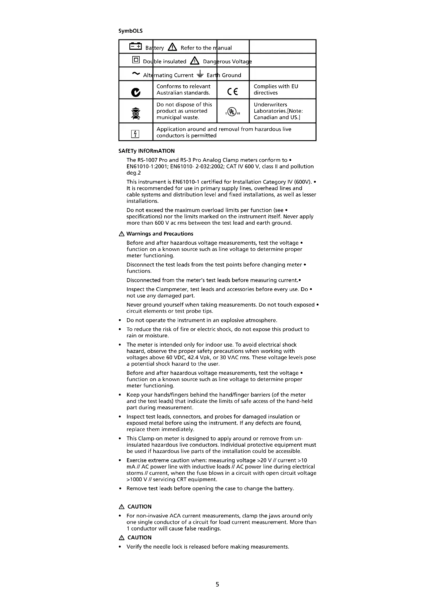
Measuring AC Voltage (See Fig. 1)
CAUTION
Remove clamp jaws from wire before connecting to or measuring voltage.
Rotate the meter scale wheel to appropriate V1. range.
Using the V A Zero screw (front panel), adjust the needle for '0'.2.
Connect the test leads: Red to + and Black to COM.3.
Connect the test probes to the circuit test points.4.
Read the needle location on the meter scale and, if necessary, correct any 5. overload (needle pegged) conditions.
AC Current Measurement (See Fig. 2)
CAUTION
Disconnect test leads from circuit and meter if voltage was being tested.
Rotate the meter scale wheel to appropriate A1. range.
Using the V A Zero screw (front panel), adjust the needle for '0'.2.
Open spring-loaded clamp by pressing the lever on left side of meter.3.
Position clamp around one wire or conductor and release the clamp lever. 4.
Read the needle location on the meter scale, and, if necessary, correct any 5. overload (needle pegged) conditions.
CAUTION
Using Resistance or Continuity function in a live circuit will produce false results and may damage the instrument. In most cases the suspected component must be disconnected from the circuit to obtain an accurate measurement reading.
Measuring Resistance /Continuity (See Fig.3)
Rotate the meter scale wheel to 1. range.
- Turn off power to the circuit being measured and discharge any capacitors in the circuit.
Connect the test leads: Red to + and Black to COM.3. - Short the test leads and adjust Zero knob for 0^ .
- Remove the short from the test leads.
- Using the V A Zero screw, adjust the needle for
- Connect the test probes across the resistance.
Read the needle location on the meter scale, and, if necessary, correct any 8. overload (needle pegged) conditions.
MAINTENANCE AND REPAIR
If there appears to be a malfunction during the operation of the meter, the following steps should be performed in order to isolate the cause of the problem:
Verify the needle lock is disengaged (all the way to the left). Needle 1. should move when meter is moved.
- Check the battery and fuse (ohms range only).
- Review the operating instructions for possible mistakes in operating procedure.
- Inspect and test the test leads for a broken or intermittent connection. Except for the replacement of the fuse, battery or test probes, repair of the multimeter should be performed only by a Factory Authorized Service Center
or by other qualified instrument service personnel. The front panel and case can be cleaned with a mild solution of detergent and water. Apply sparingly with a soft cloth and allow to dry completely before using. Do not use aromatic hydrocarbons or chlorinated solvents for cleaning.
Battery Replacement (see Fig. 4)
Warning
To prevent electrical shock or meter damage, disconnect the meter's test leads from any circuit and the meter, then turn the meter off before removing the battery cover. Battery replacement should be performed in a clean environment and with appropriate care taken to avoid contaminating the meter's interior components.
Remove the screw and lift the battery cover.1.
Remove the battery using the pull strap.2.
Replace the battery with the same type, 1.5 V AAA battery (NEDA-24A, IEC 3. LR03). Note polarity of the battery.
Replace the battery cover and screw.4.
Fuse Replacement
Remove the screw and lift the battery cover.1.
Remove the battery using the pull strap.2.
Remove the fuse using the pull strap.3.
Replace the fuse with F 0.5 A Fuse (FP500)4.
Replace the battery noting the polarity of the battery.5.
Replace the battery cover and screw.6.
SPECIFICATIONS
General
Display: Analog scales with clamping needle
Power Supply:
Volts / amps: powered by circuit under test
Ohms: 1.5 V AAA battery (ANSI/NEDA-24A, IEC LR03)
Low Battery: Below approx. 1.2 V
Environmental: Indoor operation; below 2000m (6,562ft)
Operating Temperature: -15°C to 50°C (5°F to 122°F); < 80%
Storage Temperature: -20^ to 60^ (-4^ to 140^) < 80% R.H. (with battery removed)
Temperature Coefficient: nominal 0.15 x (specified accuracy)/°C @ 0°C to 18°C or 28°C to 40°C (32°F to 64°F or 82°F to 104°F)
Dimension:
RS-1007 Pro: 261 × 102 × 41 mm (10.3 × 4.0 × 1.6 in.)
RS-3 Pro: 243 × 102 × 41 mm (10.3 x 4.0 x 1.6 in.)
Weight:
RS-1007 Pro: 0.474 kg (1.05 lb.)
RS-3 Pro: 0.455kg (1.0 lb.)
Jaw opening / Conductor diameter:
RS-1007 PRO: 47mm (1.88") max
RS-3 PRO: 41mm (1.64") max
Safety LVD: Meets EN60101-1:2001; EN61010-2-032(2002), Category IV - 600 Volts ac; pollution degree : II; class 2
CE EMC: EN 61326-1:2006 This product complies with requirements of the following European Community Directives: 2004/108/EC (Electromagnetic Compatibility) and 2006/95/EC (Low Voltage) as amended by 93/68/EEC (CE Marking). However, electrical noise or intense electromagnetic fields in the vicinity of the equipment may disturb the measurement circuit. Measuring instruments will also respond to unwanted signals that may be present within the measurement circuit. Users should exercise care and take appropriate precautions to avoid misleading results when making measurements in the presence of electronic interference.
Electrical 23^ ± 5^ ( 73^ ± 9^ ) <75%RH
AC Voltage (50/60 Hz)
Ranges: 150 / 300 / 600 Vrms
Accuracy: ± 3% of Full Scale.
Input Impedance: 1.5 MΩ
OL Protection: 600 V ac rms
AC Amp (50/60 Hz)
Ranges:
RS-1007 Pro: 15/40/100/300/1000 Arms
RS-3 Pro: 6 / 15 / 40 / 100 /600 Arms
Accuracy: ± 3 % of Full Scale
Ohms
Range: 1000 ohms
25 Ohms mid-scale
Accuracy: ± 3 degrees of Arc
Open Circuit voltage: 1.5v
Short circuit Current: 58 mA
OL Protection: (F 0.5 A / 1000 V, size 6 x 32 mm IR fast blow ceramic)
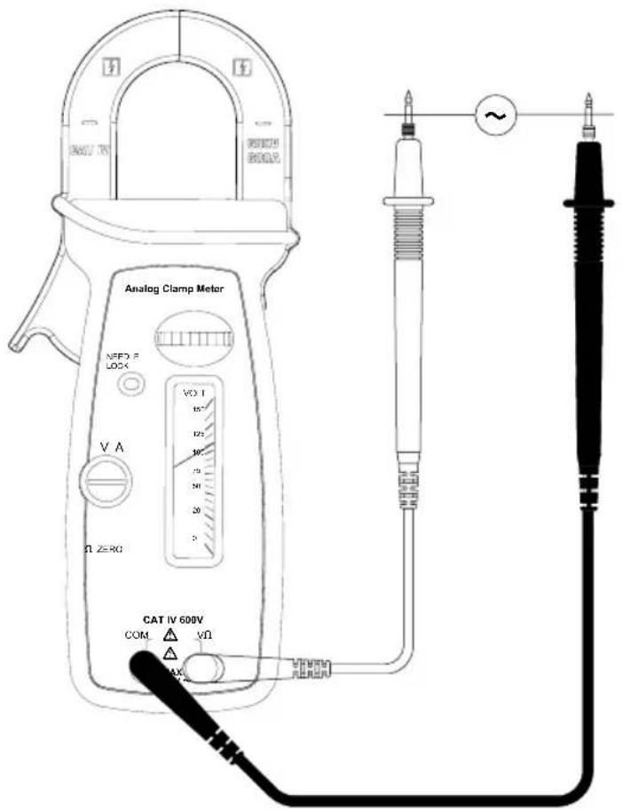
Fig 1. Volts
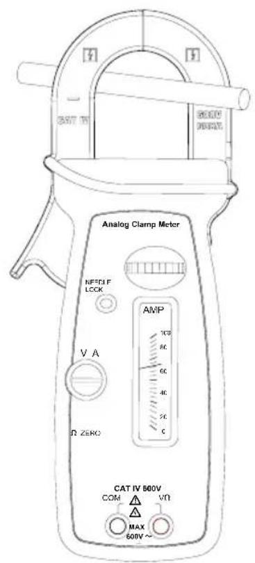
Fig 2. Amps

Fig 3. Ohms
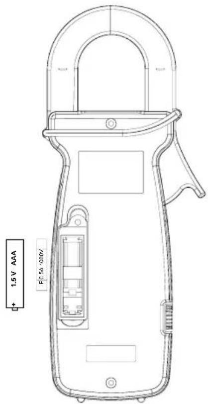
Fig. 4 Battery Fuse
AMPROBE
RS-3 PRO
RS-1007 PRO
Amprobe Test Tools Amprobe Test Tools
Everett, WA 98203 Mississauga, ON L4Z 1X9
Tel: 888-993-5853 Tel: 905-890-7600
Fax: 425-446-6390 Fax: 905-890-6866
Amprobe Test Tools Europe
Beha-Amprobe GmbH
In den Engematten 14
79286 Glottertal, Germany
Tel.: +49 (0) 7684 8009 - 0
RS-3 Pro:0,455 kg (1,0 lb)
Tension c.a. (50/60 Hz)
Gammes: 150/300/600 V eff.
Ampere c.a. (50/60 Hz)
Gammes:
RS-1007 Pro : 15 / 40 / 100 / 300 / 1000 A eff.
RS-3 Pro : 6 / 15 / 40 / 100 /600 A eff.
Amprobe Test Tools Amprobe Test Tools
Everett, WA 98203 Mississauga, ON L4Z 1X9
Tel: 877-AMPROBE (267-7623) Tel: 905-890-7600
Fax:425-446-6390 Fax:905-890-6866
Amprobe Test Tools Europe
Beha-Amprobe GmbH
In den Engematten 14
79286 Glottertal, Germany
Tel.: +49 (0) 7684 8009 - 0
RS-3 PRO: max. 41 mm
RS-3 Pro: 6/15/40/100/600 Aeff.
Amprobe Test Tools Amprobe Test Tools
Everett, WA 98203 Mississauga, ON L4Z 1X9
Tel: 888-993-5853 Tel: 905-890-7600
Fax:425-446-6390 Fax:905-890-6866
Amprobe Test Tools Europe
Beha-Amprobe GmbH
In den Engematten 14
79286 Glottertal, Germania
Tel.: +49 (0) 7684 8009 - 0
RS-3 PRO: 6/15/40/100/600 A (valore efficace)
Amprobe Test Tools Amprobe Test Tools
Everett, WA 98203 Mississauga, ON L4Z 1X9
Tel: 877-AMPROBE (267-7623) Tel: 905-890-7600
Fax:425-446-6390 Fax:905-890-6866
Amprobe Test Tools Europe
Beha-Amprobe GmbH
In den Engematten 14
Amprobe Test Tools Amprobe Test Tools
Everett, WA 98203 Mississauga, ON L4Z 1X9
Tel: 888-993-5853 Tel: 905-890-7600
Fax:425-446-6390 Fax:905-890-6866
Amprobe Test Tools Europe
Beha-Amprobe GmbH
In den Engematten 14
79286 Glottertal, Tyskland
Tel.: +49 (0) 7684 8009 - 0
* (Endast correspondens - inga reparationer erller utbyten ar tillgangliga fran denna adress. Kunder i Europa sca kontakta respektive distributor.)
RS-1007 PRO: 47 mm (1,88") max
RS-3 PRO: 41 mm (1,64") max
Sakerhets-LVD: Uppfyller kraven i EN60101-1:2001; EN61010-2-032(2002), Kategori IV - 600 volt vaxelström; Förereningsgrad: II; klass 2
Visit www.Amprobe.com for
Catalog
Application notes
Product specifications
User manuals

Please Recycle


- Limited Warranty and Limitation of Liability
- Repair
- In-Warranty Repairs and Replacement - All Countries
- Non-Warranty Repairs and Replacement - US and Canada
- Non-Warranty Repairs and Replacement - Europe
- CONTENTS
- SAfETy INfORmATION
- Warnings and Precautions
- CAUTION
- UNPACKING AND CONTENTS
- INTRODUCTION
- OPERATION
- MAINTENANCE AND REPAIR
- Battery Replacement (see Fig. 4)
- Warning
- Fuse Replacement
- SPECIFICATIONS
- General
- Electrical 23°C ± 5°C ( 73°F ± 9°F ) <75%RH
- AMPROBE
Brand : Amprobe
Model : RS3PRO
Category : Measuring equipment