
RTG 95 SQF IN - Cooker ROSIERES - Free user manual and instructions
Find the device manual for free RTG 95 SQF IN ROSIERES in PDF.
| Brand | Rosieres |
| Model | RTG 95 SQF IN |
| Product type | Mixed gas / electric cooker |
| Power supply | 220-240 V ~ 50/60 Hz |
| Gas supply | Natural gas (G20/G25) or liquefied gas (G30/G31) – adaptable |
| Number of gas burners | 5 (rapid, semi-rapid, auxiliary, wok, fish) |
| Maximum burner power | Up to 4800 W (wok burner) |
| Ignition | Automatic by spark plug (integrated or separate depending on version) |
| Safety | Thermoelectric on some burners (gas shut-off if flame goes out) |
| Electric / ceramic hobs | 2 radiant ceramic hobs (single or triple circuit) |
| Maximum electric power | 1800 W per element |
| Hob adjustment | Switching (0-6) or energy regulator (0-11) |
| Installation class | Class 3 (freestanding appliance) |
| Maintenance – Burners | Clean with boiling water and detergent; unclog orifices |
| Maintenance – Ceramic glass | Clean with metal scraper and suitable product (Sidol, Shahfix); avoid abrasive sponges |
| Maintenance – General | Non-abrasive products; do not use steam cleaner |
| Gas type adaptation | Change injectors and adjust idle speed (screwdriver) |
| Available spare parts | Injectors, valves, spark plugs, seals |
| Reparability | Greasing valves and replacing power cable by a professional |
| Required room volume | Adequate ventilation (2.0 m³/h per kW of installed power) |
Frequently Asked Questions - RTG 95 SQF IN ROSIERES
User questions about RTG 95 SQF IN ROSIERES
0 question about this device. Answer the ones you know or ask your own.
Ask a new question about this device
Download the instructions for your Cooker in PDF format for free! Find your manual RTG 95 SQF IN - ROSIERES and take your electronic device back in hand. On this page are published all the documents necessary for the use of your device. RTG 95 SQF IN by ROSIERES.
USER MANUAL RTG 95 SQF IN ROSIERES
COOKING HOB ELECTROGAS
Installation - Use - Maintenance
TABLES DE CUISSON ÉLECTROGAZ
Installation - Emploi - Entretien
We thank you and congratulate you on your choice.
This new carefully designed product, manufactured with the highest quality materials, has been carefully tested to satisfy all your cooking demands. We would therefore request you to read and follow these easy instructions which will allow you to obtain excellent results right from the start.
May we wish you all the very best with your modern appliance!
THE MANUFACTURER
Index
Instructions for use 16
Installation 16
Use 16
Maintenance Gas/Electrical 20
Maintenance vitroceramic surface 20
Instructions for the installer 21
Installation 21
Positioning 21
Gas connection 21
Electrical connection 21
Adaptation to various types of gas 22
THIS APPLIANCE IS CONCEIVED FOR DOMESTIC USE ONLY.
THE MANUFACTURER SHALL NOT IN ANYWAYBEHELDRESPONSIBLE FOR WHATEVER INJURIES OR DAMAGES ARE CAUSED BY INCORRECT INSTALLATION OR BY UNSUITABLE,WRONG OR ABSURD USE.
THIS APPLIANCE IS NOT INTENDED FOR USE BY PERSONS (INCLUDING CHILDREN) WITH REDUCED PHYSICAL, SENSORY OR MENTAL
CAPABILITIES, OR LACK OF EXPERIENCE AND KNOWLEDGE, UNLESS THEY HAVE BEEN GIVEN SUPERVISION OR INSTRUCTION
CONCERNING USE OF THE APPLIANCE BY A PERSON RESPONSIBLE FOR THEIR SAFETY. CHILDREN SHOULD BE SUPERVISED TO ENSURE THAT THEY DO NOT PLAY WITH THE APPLIANCE..
Instructions for use
Installation

All the operations concerned with the installation (electrical and gas connections, adaptation to type of gas, necessary adjustments, etc.) must be carried out by qualified technicians, in terms with the standards in force.
For specific instructions, kindly read the part reserved for the installation technician.
Use
Gas burners (Fig. 1-3).
The ignition of the gas burner is carried out by putting a small flame to the upper part holes of the burner, pressing and rotating the corresponding knob in an anti-clockwise manner, until the maximum position has coincided with the marker. When the gas burner has been turned on, adjust the flame according to need. The minimum position is found at the end of the anti-clockwise rotation direction.
In models with automatic ignition, operate the knob as described above, pressing simultaneously, the corresponding push-button. For models with automatic/ simultaneous (with one hand) ignition, it is sufficient to proceed as described above using the corresponding knob. The electric spark between the ignition plug and the burner provides the ignition of the burner itself. After ignition, immediately release the push-button and adjust the flame according to need.
For models with a thermoelectric safety system, the burner is ignited as in
the various cases described above, keeping the knob fully pressed on the maximum position for approximately 3/5 seconds. After releasing the knob, make sure the burner is actually lit.
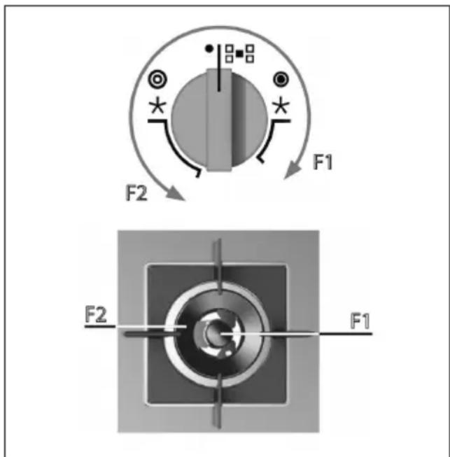
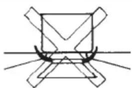
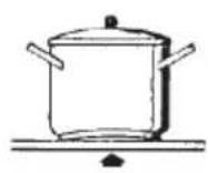
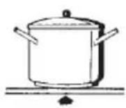
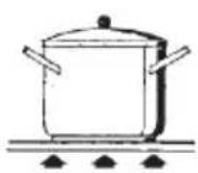
N.B. - we recommend the use of pots and pans with a diameter matching that of the burner, thus preventing the flame from escaping from the bottom part and surrounding the pot
- do not leave any empty pots or pans on the fire
- do not use any tools for grill-cooking on Crystal hobs.
When cooking is finished, it is also a good norm to close the main gas pipe tap and/ or cylinder.
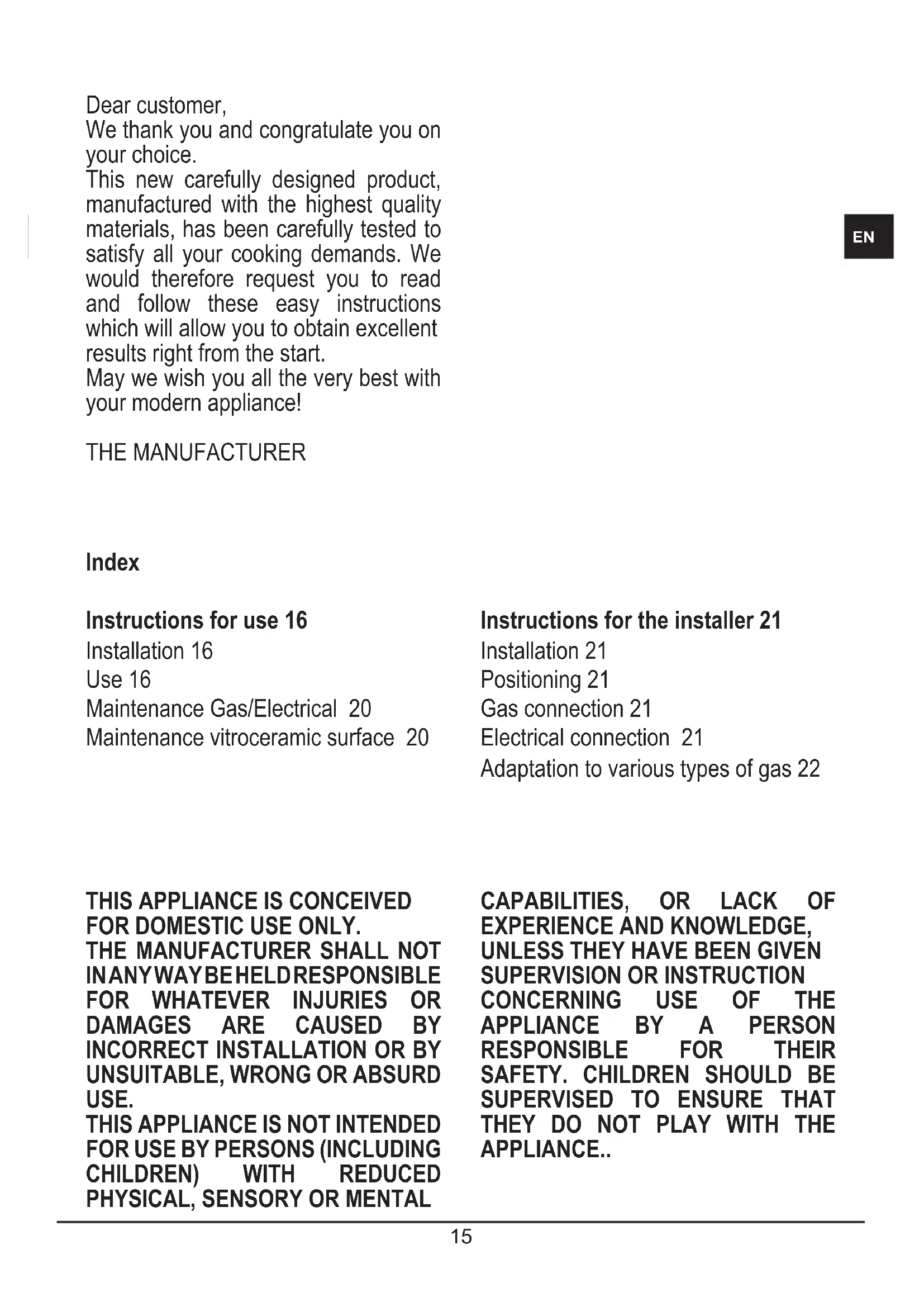
Models with Dual Wok burner
Some models have a Dual Wok burner. The centre flame (F1) can be lit by pressing the knob and turning it clockwise or the entire burner (F2) can be lit as shown the figure below.
Important
- use of the appliance produces heat and moisture in the room where it is installed. Make sure the kitchen is sufficiently ventilated; keep natural ventilation holes open or install mechanical ventilation devices (such as a hood).
- Prolonged use of the appliance may require additional ventilation, such as opening a window.
- on floors with thermoelectric protection do not keep the ignite button pushed for more than 15 seconds. If the burner has not ignited after 15 seconds, open the door of the room and wait at least one minute before making a further attempt.
- on floors without protection, should the burner flame go out close the corresponding gas cock and wait at least on minute before making any attempt to ignite it.
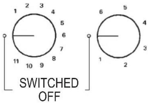
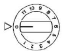
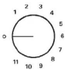
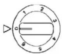
Electrical plates / Vitroceramic heating element
(Fig. 2-2a-3). Rotate the knob towards the position required for cooking and bear in mind that the higher the number, the higher the heat output. See table "use of electrical plates"/heatin elements vitroceramic. The pilot light signals that the plate is "on".
Some types of pilot lights will maintain some slight luminescence even after disconnection. That is quite normal.
N.B.: When using electrical plates/ heating elements vitroceramic, we
recommend flat bottom recipients with a diameter equal or slightly larger than that of the plate itself.
- avoid liquid overflow. Therefore, after boiling or heating liquids, reduce the heat output;
- do not leave the electrical plates on with empty pots and pans;
- when cooking is finished, rotate the knob back into closing and/or disconnected position.
In the event of even a slight fracture on the cooking vitroceramic surface, disconnect the electric power supply immediately.
DO NOT STARE AT THE HALOGEN LAMP.
GAS
fish 20x32
wok 20-32
fast 20-26
semifast 0 14-20
auxiliary * 10-14
*with reduction grid
Fig. 1

ELECTRICAL PLATES
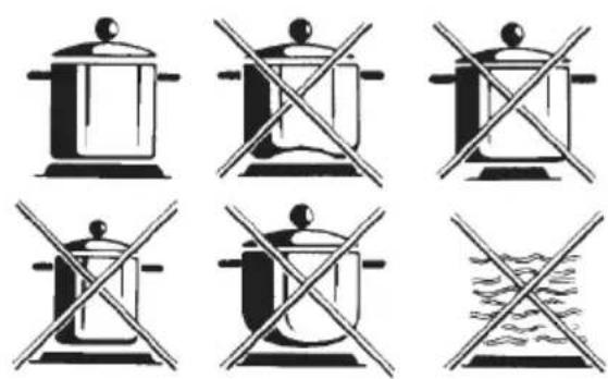
Fig. 2
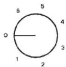
VITROCERAMIC HEATING ELEMENTS
no no yes
Fig. 2a
| USE OF ELECTRICAL PLATES/VITROCERAMIC HEATING ELEMENTS | |
| Commutator Energy regulator Heat intensity Cooking methods | |
| 1 1-2 slight | melting of fats etc.; heat small quantities of liquid |
| 2 3-4 mild | heating of medium quantities of liquid; puddings, long-cooking sauces |
| 3 5-6 slow | defreezing - heat large quantities of liquid; cooking below boiling temperature |
| 4 7 - 8 medium | tender roasts; cooking at boiling temperature |
| 5 9 - 10 high | roasts - boiled food; pan-frying of meats |
| 6 10 - 11 burning heat | bring large quantities of liquid to boil; fry |
EN
Maintenance Gas/Electrical

Prior to any operation, disconnect the appliance from the electrical system.
For long-life to the equipment, a general cleaning operation must take place periodically, bearing in mind the following:
- the glass, steel and/or enamelled parts must be cleaned with suitable non-abrasive or corrosive products (found on the market). Avoid chlorine-base products (bleach, etc.);
- avoid leaving acid or alkaline substances on the working area (vinegar, salt, lemon juice, etc.).
- the wall baffle and the small covers (mobile parts of the burner) must be washed frequently with boiling water and detergent, taking care to remove every possible encrustation. Dry carefully and check that none of the burner holes is fully or partially clogged;
- the electrical parts are cleaned with a damp cloth and are lightly greased with lubricating oil when still warm.
- the stainless steel grids of the working area, after having been heated, take on a bluish tint which does not deteriorate the quality. To bring colour back to its original state, use a slightly abrasive product.
N.B.- Cleaning of the taps must be carried out by qualified personnel, who must be consulted in case of any functioning anomaly. Check periodically the state of conservation of the flexible gas feed pipe. In case of leakage, call immediately the qualified technicians for its replacement.
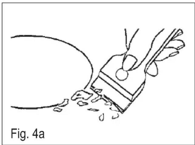
Maintenance vitroceramic surface
(Fig.-4a) First of all remove stray food bits and grease drops from the cooking surface with the special scraper (fig. 4). Then clean the hot area as best as possible with SIDOL, STAHLFIX or other similar products with a papertowel, then rinse again with water and dry with a clean cloth.
Pieces of aluminum foil and plastic material which have inadvertently melted or sugar remains or highly sacchariferous food have to be removed immediately from the hot cooking area with the special scraper (fig. 4).-This is to avoid any possible damage to the surface of the top.
Under no circumstances should abrasive sponges or irritating chemical detergents be used such as oven sprays or spot removers.
DO NOT USE STEAM CLEANERS
Instructions for the installer
Installation
This appliance is not provided with a combustion product discharge. It is recommended that it be installed in sufficiently aerated places, in terms of the laws in force. The quantity of air which is necessary for combustion must not be below 2.0m3 / h for each kW of installed power.
See table of burner power.
Note: the device is in installation class 3. The appliance's adjustment parameters are shown on the plate attached to its housing.
Positioning
(Fig. 4). The appliance can be fitted into a working area as illustrated on the corresponding figure. Before positioning the hob, fit the seal around the entire periphery of the hole cut in the worktop.
Gas connection
(Fig. 5) Connect the appliance to the gas cylinder or to the installation according to the prescribed standards in force, and ensure beforehand, that the appliance matches the type of gas available.
Otherwise, see "Adaptation to various types of gas".
Furthermore, check that the feed pressure falls within the values described on the table: "User characteristics".
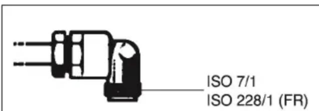
Fig. 5

Rigid/semi rigid metal connection
Carry out the connection with fittings and metal pipes (even flexible pipes) so as to obtain counter stress the inner parts of the appliance.
N.B. - when the installation has been carried out, check the perfect sealing of the entire connection system, by using a soapy solution.
Electrical connection
(Fig. 6) Prior to carrying out the electrical connection, please ensure that:
- the plant characteristics are such as to follow what is indicated on the matrix plate placed at the bottom of the working area;
- that the plant is fitted with an efficient earth connection, following the standards and law provisions in force. The earth connection is compulsory in terms of the law.
Should there be no cable and/or plug on the equipment, use suitable absorption material for the working temperature as well, as indicated on the matrix plate. Under no circumstance must the cable reach a temperature above 50^ of the ambient temperature.
If connecting directly to the mains power supply, fit a multi-pole switch of a

suitable size for the rated capacity with a clearance distance which completely disconnects the power line under overvoltage category III conditions, consistently with the rules of installation (the yellow/green earth wir must not be interrupted). The plug or omnipolar switch must be easily reached on the installed equipment.
To avoid all risk, if the power cable becomes damaged, it must only be replaced by the manufacturer, by an authorised service centre, or by a qualified electrician.
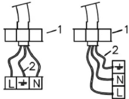
1-CABLE-CLAMP
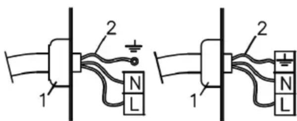
2 - YELLOW / GREEN
Fig. 6
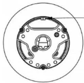
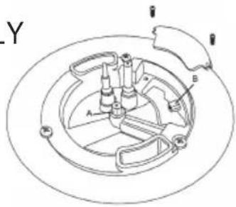
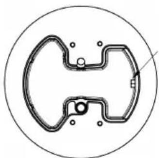
Adaptation to various types of gas
(Fig. 7) Should the appliance be re-set for a different type of gas than available, proceed as follows:
- replace the injectors (Fig. 7) with the corresponding type of gas to be used (see table "Uses characteristics")
to adjust to the minimum, use a screwdriver on the screw placed on the tap (Fig. 8) after turning the tap to its minimum position. For LPG (butane / propane) screw tight.
WOK ONLY
WOK TCD ONLY
CE PRODUIT EST CONCU EXCLUSIVEMENT POUR USAGE DOMESTIQUE.
LE CONSTRUCTEUR DÉCLINE
TOUTE RESPONSABILITÉ POUR
DOMMAGES ET BLESSURES
CAUSEES PAR UNE INSTALLATION
INCORRECTE OU PAR UN USAGE
IMPROPRE, ERRONE OU ABSURDE.
L'APPEAR NE DOIT PAS ETRE
UTILISÉ PAR DES PERSONNES
(ENFANTS INCLUS) DISPOSANT DE
CAPACITES PHYSIQUES,
SENSORIELLES OU MENTALES
INSTRUCTIONS RELATIVES
- COOKING HOB ELECTROGAS
- TABLES DE CUISSON ÉLECTROGAZ
- Index
- Instructions for use
- Installation
- Use
- Gas burners (Fig. 1-3).
- Models with Dual Wok burner
- Important
- Electrical plates / Vitroceramic heating element
- Maintenance Gas/Electrical
- Maintenance vitroceramic surface
- Instructions for the installer
- Positioning
- Gas connection
- Rigid/semi rigid metal connection
- Electrical connection
- Adaptation to various types of gas
Brand : ROSIERES
Model : RTG 95 SQF IN
Category : Cooker