Z97 Extreme3 - Motherboard ASROCK - Free user manual and instructions
Find the device manual for free Z97 Extreme3 ASROCK in PDF.
Download the instructions for your Motherboard in PDF format for free! Find your manual Z97 Extreme3 - ASROCK and take your electronic device back in hand. On this page are published all the documents necessary for the use of your device. Z97 Extreme3 by ASROCK.
USER MANUAL Z97 Extreme3 ASROCK
Version 1.1 Published May 2014 Copyright©2014 ASRock INC. All rights reserved. Copyright Notice: No part of this documentation may be reproduced, transcribed, transmitted, or translated in any language, in any form or by any means, except duplication of documentation by the purchaser for backup purpose, without written consent of ASRock Inc. Products and corporate names appearing in this documentation may or may not be registered trademarks or copyrights of their respective companies, and are used only for identication or explanation and to the owners’ benet, without intent to infringe. Disclaimer: Specications and information contained in this documentation are furnished for informational use only and subject to change without notice, and should not be constructed as a commitment by ASRock. ASRock assumes no responsibility for any errors or omissions that may appear in this documentation. With respect to the contents of this documentation, ASRock does not provide warranty of any kind, either expressed or implied, including but not limited to the implied warranties or conditions of merchantability or tness for a particular purpose. In no event shall ASRock, its directors, ocers, employees, or agents be liable for any indirect, special, incidental, or consequential damages (including damages for loss of prots, loss of business, loss of data, interruption of business and the like), even if ASRock has been advised of the possibility of such damages arising from any defect or error in the documentation or product. is device complies with Part 15 of the FCC Rules. Operation is subject to the following two conditions: (1) this device may not cause harmful interference, and (2) this device must accept any interference received, including interference that may cause undesired operation.
CALIFORNIA, USA ONLY
e Lithium battery adopted on this motherboard contains Perchlorate, a toxic substance controlled in Perchlorate Best Management Practices (BMP) regulations passed by the California Legislature. When you discard the Lithium battery in California, USA, please follow the related regulations in advance. “Perchlorate Material-special handling may apply, see www.dtsc.ca.gov/hazardouswaste/ perchlorate” ASRock Website: http://www.asrock.come terms HDMI™ and HDMI High-Denition Multimedia Interface, and the HDMI logo are trademarks or registered trademarks of HDMI Licensing LLC in the United States and other countries.1 Z97 Extreme3 English Motherboard Layout Intel Z97 DDR3_A2 (64 bit, 240-pin module)DDR3_A1 (64 bit, 240-pin module)DDR3_B2 (64 bit, 240-pin module)DDR3_B1 (64 bit, 240-pin module)ATX 12V1Supe r I/O
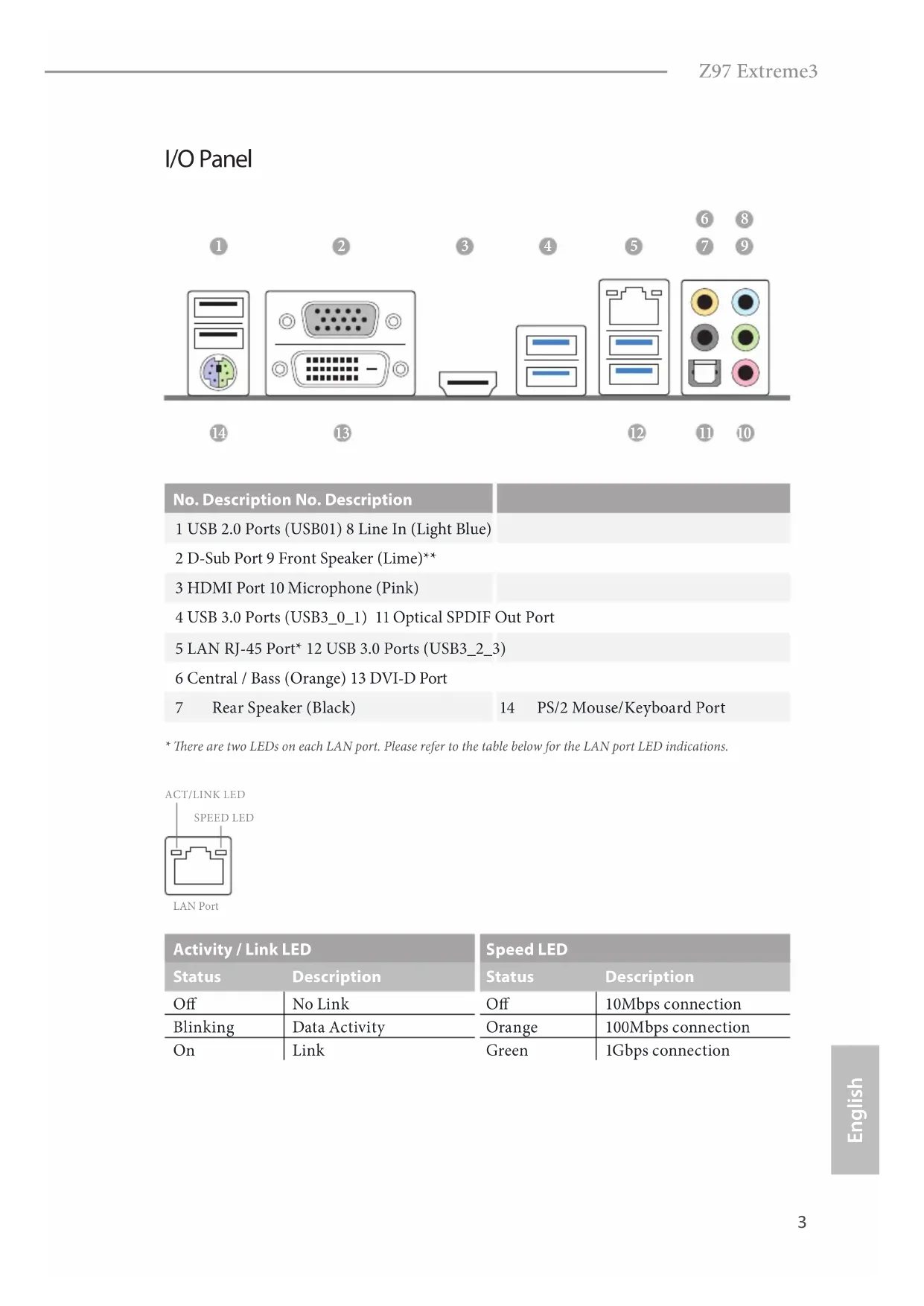
- ere are two LEDs on each LAN port. Please refer to the table below for the LAN port LED indications. Activity / Link LED Speed LED Status Description Status Description O No Link O 10Mbps connection Blinking Data Activity Orange 100Mbps connection On Link Green 1Gbps connection
ACT/LINK LEDSPEED LEDLAN Port4 English ** If you use a 2-channel speaker, please connect the speaker’s plug into “Front Speaker Jack”. See the table below for connection details in accordance with the type of speaker you use. Audio Output Channels Front Speaker (No. 9) Rear Speaker (No. 7) Central / Bass (No. 6) Line In (No. 8) 2 V -- -- -- 4 V V -- -- 6 V V V -- 8 V V V V To enable Multi-Streaming, you need to connect a front panel audio cable to the front panel audio header. Aer restarting your computer, you will nd the “Mixer” tool on your system. Please select “Mixer ToolBox” , click “Enable playback multi-streaming”, and click “ok”. Choose “2CH”, “4CH”, “6CH”, or “8CH” and then you are allowed to select “Realtek HDA Primary output” to use the Rear Speaker, Central/Bass, and Front Speaker, or select “Realtek HDA Audio 2nd output” to use the front panel audio.5 Z97 Extreme3 English
Chapter 1 Introduction
ank you for purchasing ASRock Z97 Extreme3 motherboard, a reliable motherboard produced under ASRock’s consistently stringent quality control. It delivers excellent performance with robust design conforming to ASRock’s commitment to quality and endurance.
- 1 x ASRock SLI_Bridge_2S Card Because the motherboard specications and the BIOS soware might be updated, the content of this documentation will be subject to change without notice. In case any modi-cations of this documentation occur, the updated version will be available on ASRock’s website without further notice. If you require technical support related to this mother-board, please visit our website for specic information about the model you are using. You may nd the latest VGA cards and CPU support list on ASRock’s website as well. ASRock website http://www.asrock.com.6 English
- High Density Glass Fabric PCB CPU
- 8 Power Phase design
- Supports Intel® Turbo Boost 2.0 Technology
- Supports Intel® K-Series unlocked CPUs
- Supports ASRock BCLK Full-range Overclocking Chipset
- Dual Channel DDR3 Memory Technology
- Max. capacity of system memory: 32GB
- Intel® HD Graphics Built-in Visuals and the VGA outputs can be supported only with processors which are GPU integrated.
- Supports Intel® HD Graphics Built-in Visuals : Intel® Quick Sync Video with AVC, MVC (S3D) and MPEG-2 Full HW Encode1, Intel® InTru
- Supports Triple Monitor
- Supports HDMI with max. resolution up to 4K x 2K (4096x2304) @ 24Hz
- Supports DVI-D with max. resolution up to 1920x1200 @ 60Hz
- Supports D-Sub with max. resolution up to 1920x1200 @ 60Hz
- Supports Auto Lip Sync, Deep Color (12bpc), xvYCC and HBR (High Bit Rate Audio) with HDMI Port (Compliant HDMI monitor is required)
- Supports HDCP with DVI-D and HDMI Ports
- Supports Full HD 1080p Blu-ray (BD) playback with DVI-D and HDMI Ports Audio
- Supports Surge Protection (ASRock Full Spike Protection)
- Supports Intel® Remote Wake Technology
- Supports Wake-On-LAN
- Supports Lightning/ESD Protection (ASRock Full Spike Protection)
- Supports Energy Ecient Ethernet 802.3az
- Supports PXE8 English Rear Panel I/O
- 2 x USB 2.0 Ports (Supports ESD Protection (ASRock Full Spike Protection))
- 4 x USB 3.0 Ports (Supports ESD Protection (ASRock Full Spike Protection))
- 1 x RJ-45 LAN Port with LED (ACT/LINK LED and SPEED LED)
- HD Audio Jacks: Rear Speaker / Central / Bass / Line in / Front Speaker / Microphone Storage
- 6 x SATA3 6.0 Gb/s Connectors, support RAID (RAID 0, RAID 1, RAID 5, RAID 10, Intel Rapid Storage Technology 13 and Intel Smart Response Technology), NCQ, AHCI and Hot Plug Connector
- 2 x CPU Fan Connectors (1 x 4-pin, 1 x 3-pin)
- 3 x Chassis Fan Connectors (1 x 4-pin, 2 x 3-pin)
- 1 x Power Fan Connector (3-pin)
- 1 x Front Panel Audio Connector
- 2 x USB 2.0 Headers (support 4 USB 2.0 ports) (Supports ESD Protection (ASRock Full Spike Protection))
- 1 x USB 3.0 Header (support 2 USB 3.0 ports) (Supports ESD Protection (ASRock Full Spike Protection)) BIOS Feature
- 64Mb AMI UEFI Legal BIOS with multilingual GUI support
- ACPI 1.1 Compliant wake up events
- CPU/Chassis temperature sensing
- CPU/Chassis/Power Fan Tachometer
- CPU/Chassis Quiet Fan (Auto adjust chassis fan speed by CPU temperature)
- CPU/Chassis Fan multi-speed control
- ErP/EuP ready (ErP/EuP ready power supply is required) Please realize that there is a certain risk involved with overclocking, including adjusting the setting in the BIOS, applying Untied Overclocking Technology, or using third-party overclocking tools. Overclocking may aect your system’s stability, or even cause damage to the components and devices of your system. It should be done at your own risk and expense. We are not responsible for possible damage caused by overclocking.
- For detailed product information, please visit our website: http://www.asrock.com Due to limitation, the actual memory size may be less than 4GB for the reservation for sys- tem usage under Windows® 32-bit operating systems. Windows® 64-bit operating systems do not have such limitations. You can use ASRock XFast RAM to utilize the memory that Windows® cannot use.10 English is is an ATX form factor motherboard. Before you install the motherboard, study the conguration of your chassis to ensure that the motherboard ts into it. Pre-installation Precautions Take note of the following precautions before you install motherboard components or change any motherboard settings.
- Make sure to unplug the power cord before installing or removing the motherboard components. Failure to do so may cause physical injuries to you and damages to motherboard components.
- In order to avoid damage from static electricity to the motherboard’s components, NEVER place your motherboard directly on a carpet. Also remember to use a grounded wrist strap or touch a safety grounded object before you handle the components.
- Hold components by the edges and do not touch the ICs.
- Whenever you uninstall any components, place them on a grounded anti-static pad or in the bag that comes with the components.
- When placing screws to secure the motherboard to the chassis, please do not over- tighten the screws! Doing so may damage the motherboard.
2.1 Installing the CPU
1. Before you insert the 1150-Pin CPU into the socket, please check if the PnP cap is on the
socket, if the CPU surface is unclean, or if there are any bent pins in the socket. Do not force to insert the CPU into the socket if above situation is found. Otherwise, the CPU will be seriously damaged.
Please save and replace the cover if the processor is removed. e cover must be placed if you wish to return the motherboard for aer service.13 Z97 Extreme3 English
2.2 Installing the CPU Fan and Heatsink
is motherboard provides four 240-pin DDR3 (Double Data Rate 3) DIMM slots, and supports Dual Channel Memory Technology. Dual Channel Memory Conguration e DIMM only ts in one correct orientation. It will cause permanent damage to the motherboard and the DIMM if you force the DIMM into the slot at incorrect orientation. Priority DDR3_A1 DDR3_A2 DDR3_B1 DDR3_B2 1 Populated Populated 2 Populated Populated 3 Populated Populated Populated Populated
1. For dual channel conguration, you always need to install identical (the same brand,
speed, size and chip-type) DDR3 DIMM pairs.
2. It is unable to activate Dual Channel Memory Technology with only one or three memory
3. It is not allowed to install a DDR or DDR2 memory module into a DDR3 slot; otherwise,
this motherboard and DIMM may be damaged.15 Z97 Extreme3 English
2.4 Expansion Slots (PCI and PCI Express Slots)
ere are 3 PCI slots and 3 PCI Express slots on the motherboard. PCI slots: PCI slots are used to install expansion cards that have the 32-bit PCI interface. PCIe slots: PCIE1 (PCIe 2.0 x1 slot) is used for PCI Express x1 lane width cards. PCIE2 (PCIe 3.0 x16 slot) is used for PCI Express x16 lane width graphics cards. PCIE3 (PCIe 3.0 x16 slot) is used for PCI Express x8 lane width graphics cards. PCIe Slot Congurations PCIE2 PCIE3 Single Graphics Card x16 N/A Two Graphics Cards in CrossFireX
Mode x8 x8 For a better thermal environment, please connect a chassis fan to the motherboard’s chas- sis fan connector (CHA_FAN1, CHA_FAN2 or CHA_FAN3) when using multiple graphics cards. Before installing an expansion card, please make sure that the power supply is switched o or the power cord is unplugged. Please read the documentation of the expansion card and make necessary hardware settings for the card before you start the installation.17 Z97 Extreme3 English
e illustration shows how jumpers are setup. When the jumper cap is placed on the pins, the jumper is “Short”. If no jumper cap is placed on the pins, the jumper is “Open”. e illustration shows a 3-pin jumper whose pin1 and pin2 are “Short” when a jumper cap is placed on these 2 pins. Clear CMOS Jumper (CLRMOS1) (see p.1, No. 18) CLRMOS1 allows you to clear the data in CMOS. To clear and reset the system parameters to default setup, please turn o the computer and unplug the power cord from the power supply. Aer waiting for 15 seconds, use a jumper cap to short pin2 and pin3 on CLRMOS1 for 5 seconds. However, please do not clear the CMOS right aer you update the BIOS. If you need to clear the CMOS when you just nish updating the BIOS, you must boot up the system rst, and then shut it down before you do the clear-CMOS action. Please be noted that the password, date, time, and user default prole will be cleared only if the CMOS battery is removed. Clear CMOSDefault18 English
2.6 Onboard Headers and Connectors
System Panel Header (9-pin PANEL1) (see p.1, No. 17) Connect the power switch, reset switch and system status indicator on the chassis to this header according to the pin assignments below. Note the positive and negative pins before connecting the cables. GND
RESET#PWRBTN#PLED-PLED+
GND PWRBTN (Power Switch): Connect to the power switch on the chassis front panel. You may congure the way to turn o your system using the power switch. RESET (Reset Switch): Connect to the reset switch on the chassis front panel. Press the reset switch to restart the computer if the computer freezes and fails to perform a normal restart. PLED (System Power LED): Connect to the power status indicator on the chassis front panel. e LED is on when the system is operating. e LED keeps blinking when the system is in S1/S3 sleep state. e LED is o when the system is in S4 sleep state or powered o (S5). HDLED (Hard Drive Activity LED): Connect to the hard drive activity LED on the chassis front panel. e LED is on when the hard drive is reading or writing data. e front panel design may dier by chassis. A front panel module mainly consists of power switch, reset switch, power LED, hard drive activity LED, speaker and etc. When connect- ing your chassis front panel module to this header, make sure the wire assignments and the pin assignments are matched correctly. Onboard headers and connectors are NOT jumpers. Do NOT place jumper caps over these headers and connectors. Placing jumper caps over the headers and connectors will cause permanent damage to the motherboard.19 Z97 Extreme3 English Power LED Header (3-pin PLED1) (see p.1, No. 15) Please connect the chassis power LED to this header to indicate the system’s power status. Serial ATA3 Connectors (SATA3_0) (see p.1, No. 9) (SATA3_1) (see p.1, No. 10) (SATA3_2) (see p.1, No. 11) (SATA3_3) (see p.1, No. 12) (SATA3_4) (see p.1, No. 13) (SATA3_5) (see p.1, No. 14) ese six SATA3 connectors support SATA data cables for internal storage devices with up to 6.0 Gb/s data transfer rate. USB 2.0 Headers (9-pin USB2_3) (see p.1, No. 20) (9-pin USB4_5) (see p.1, No. 21) DUMMY GND GND
Besides two USB 2.0 ports on the I/O panel, there are two headers on this motherboard. Each USB
2.0 header can support two
ports. USB 3.0 Header (19-pin USB3_4_5) (see p.1, No. 8)
IntA_PB_D+DummyIntA_PB_D- GND IntA_PB_SSTX+ GND IntA_PB_SSTX-IntA_PB_SSRX+IntA_PB_SSRX-VbusVbus Vbus IntA_PA_SSRX-IntA_PA_SSRX+ GND IntA_PA_SSTX-IntA_PA_SSTX+ GND IntA_PA_D-IntA_PA_D+ Besides four USB 3.0 ports on the I/O panel, there is one header on this motherboard. Each USB
3.0 header can support two
1. High Denition Audio supports Jack Sensing, but the panel wire on the chassis must sup-
port HDA to function correctly. Please follow the instructions in our manual and chassis manual to install your system.
2. If you use an AC’97 audio panel, please install it to the front panel audio header by the
steps below: A. Connect Mic_IN (MIC) to MIC2_L. B. Connect Audio_R (RIN) to OUT2_R and Audio_L (LIN) to OUT2_L. C. Connect Ground (GND) to Ground (GND). D. MIC_RET and OUT_RET are for the HD audio panel only. You don’t need to connect them for the AC’97 audio panel. E. To activate the front mic, go to the “FrontMic” Tab in the Realtek Control panel and adjust “Recording Volume”. Front Panel Audio Header (9-pin HD_AUDIO1) (see p.1, No. 25)
MIC_RETPRESENCE# GND
is header is for connecting audio devices to the front audio panel. Chassis Speaker Header (4-pin SPEAKER1) (see p.1, No. 22)
is header supports an optional wireless transmitting and receiving infrared module.21 Z97 Extreme3 English Chassis and Power Fan Connectors (4-pin CHA_FAN1) (see p.1, No. 19) (3-pin CHA_FAN2) (see p.1, No. 6) (3-pin CHA_FAN3) (see p.1, No. 16) (3-pin PWR_FAN1) (see p.1, No. 27) GND +12V
Please connect fan cables to the fan connectors and match the black wire to the ground pin. CPU Fan Connectors (4-pin CPU_FAN1) (see p.1, No. 2) (3-pin CPU_FAN2) (see p.1, No. 3) GN D
is motherboard provides a 4-Pin CPU fan (Quiet Fan) connector. If you plan to connect a 3-Pin CPU fan, please connect it to Pin 1-3. ATX Power Connector (24-pin ATXPWR1) (see p.1, No. 7)
is motherboard provides a 24-pin ATX power con- nector. To use a 20-pin ATX power supply, please plug it along Pin 1 and Pin 13.22 English ATX 12V Power Connector (8-pin ATX12V1) (see p.1, No. 1)
is motherboard provides an 8-pin ATX 12V power connector. To use a 4-pin ATX power supply, please plug it along Pin 1 and Pin 5. PCIe Power Connector (4-pin PCIE _PWR1) (see p.1, No. 26) +12V DETECT GND Please connect a 4 pin molex power cable to this connector when more than three graphics cards are installed. Serial Port Header (9-pin COM1) (see p.1, No. 24) CCTS#1 RRTS#1 DDSR#1 DDTR#1 RRXD1 GND TTXD1 DDCD#1
RESET#PWRBTN#PLED-PLED+
RESET#PWRBTN#PLED-PLED+
- Supporta Wake-On-LAN
- Supporto la protezione da fulmini/scariche elettrostatiche (ESD) (protezione completa ASRock dai picchi di corrente)
- Supporta Energy Ecient Ethernet 802.3az
- 6 x Connettori SATA3 6,0 Gb/s, supportano RAID (RAID 0, RAID 1, RAID 5, RAID 10, Intel Rapid Storage Technology 13 e Intel Smart Response Technology), NCQ, AHCI e Hot Plug Connet- tore