
Omnia S 3.2 - Pump FERROLI - Free user manual and instructions
Find the device manual for free Omnia S 3.2 FERROLI in PDF.
| Brand | Ferroli |
| Model | Omnia S 3.2 |
| Product type | Air-to-water heat pump |
| Category | Pump |
| Power supply | 220-240 V ~ 50 Hz (single-phase) or 380-415 V 3~ 50 Hz (three-phase) depending on model |
| Nominal heating capacity (A7W35) | From 4.2 to 15.9 kW depending on model |
| COP (A7W35) | From 4.62 to 5.21 depending on model |
| Refrigerant | R32 (flammable) |
| GWP (Global Warming Potential) | 675 |
| Indoor unit weight | 33 to 36 kg depending on model |
| Outdoor unit weight | 58 to 112 kg depending on model |
| Produced water temperature range | 5°C to 65°C |
| Expansion vessel volume | 10 L |
| Recommended system pressure | 1 to 3 bar |
| Frost protection | Active below 4°C |
| Main functions | Heating, cooling, DHW production, 2-zone management, solar, rapid DHW priority, silent mode |
| External inputs | Photovoltaic, Smart Grid, room thermostat, heating/cooling switching |
| Connectivity | iOS/Android app for remote control |
| Compliance | CE, Directive 2012/19/EU (WEEE) |
| Warranty | 2 years (conditions apply) |
| Periodic maintenance | At least once a year by a qualified professional |
| Safety | Disconnect power before any intervention; use protective gloves; risk of cold/hot burns |
| Spare parts | Use only genuine Ferroli spare parts |
Frequently Asked Questions - Omnia S 3.2 FERROLI
User questions about Omnia S 3.2 FERROLI
0 question about this device. Answer the ones you know or ask your own.
Ask a new question about this device
Download the instructions for your Pump in PDF format for free! Find your manual Omnia S 3.2 - FERROLI and take your electronic device back in hand. On this page are published all the documents necessary for the use of your device. Omnia S 3.2 by FERROLI.
USER MANUAL Omnia S 3.2 FERROLI
IT MANUALE DI INSTALLAZIONE, USO E MANUTENZIONE
EN INSTALLATION, MAINTENANCE AND USER MANUAL
ES MANUAL DE INSTALLACION, USO Y MANTENIMIENTO
PT MANUAL DE INSTALLAZão, UTILIZATION E MANUTENÇAO
FR MANUEL D'INSTALLATION, D'UTILISATION ET D'ENTRETIEN
SENTINEL X100 and SENTINEL X200
FERNOX F1 and FERNOX F3
Caric. Rapido Acs (Fast Dhw)
User menu > Dhw settings > Fast Dhw
8.5.5 Service information
In this menu, you can choose the following options: (1) In the menu, you can select the option of "Elenco cronologico" and (2) In the menu, you can select the option of "L'olimo avenuto". Complete data is provided in the menu.
User menu > For Serviceman
| CURVE CLIMATICHE (WTS) MODALITA RAFFREDDAMENTO | ||||||||||
| T4 (temperatura aria estema) [°C] | -10 14 | 15 21 22 | 29 30 46 | id Curva climatica | Tipodi terminale selezionato sul tele-comando | Curve climatiche impostate | ||||
| T1S or T2S(set point acqua impianto) [°C] | 16,0 16,0 11,0 11,0 8,0 8,0 5,0 5,0 1 | Fancoil C1 | ||||||||
| 17,0 17,0 12,0 12,0 9,0 9,0 6,0 6,0 2 | ||||||||||
| 18,0 18,0 13,0 13,0 10,0 10,0 7,0 7,0 3 | ||||||||||
| 19,0 19,0 14,0 14,0 11,0 11,0 8,0 8,0 4 | ||||||||||
| 20,0 20,0 15,0 15,0 12,0 12,0 9,0 9,0 5 | ||||||||||
| 21,0 21,0 16,0 16,0 13,0 13,0 10,0 10,0 6 | ||||||||||
| 22,0 22,0 17,0 17,0 14,0 14,0 11,0 11,0 7 | ||||||||||
| 23,0 23,0 18,0 18,0 15,0 15,0 12,0 12,0 8 | ||||||||||
| 20,0 20,0 18,0 18,0 17,0 17,0 16,0 16,0 1 | Riscaldamento a pavimento radiante o radiatore | C2 | ||||||||
| 21,0 21,0 19,0 19,0 18,0 18,0 17,0 17,0 2 | ||||||||||
| 22,0 22,0 20,0 20,0 19,0 19,0 17,0 17,0 3 | ||||||||||
| 23,0 23,0 21,0 21,0 19,0 19,0 18,0 18,0 4 | ||||||||||
| 24,0 24,0 21,0 21,0 20,0 20,0 18,0 18,0 5 | ||||||||||
| 24,0 24,0 22,0 22,0 20,0 20,0 19,0 19,0 6 | ||||||||||
| 25,0 25,0 22,0 22,0 21,0 21,0 19,0 19,0 7 | ||||||||||
| 25,0 25,0 23,0 23,0 21,0 21,0 20,0 20,0 8 | ||||||||||

NOTE: 1. Equipment must be grounded. 2. All high-voltage external load, if it is metal or a grounded port, must be grounded. 3. All external load current is necessary less than O.2A, if the single load current is greater than O.2A, the load must be controlled through AC contactor. 4.AHS1*AHS2,*A1*A2,*R1*R1*and *DTF1*DTF2*wiring terminal ports provide only the switch signal. 5.Expansion valve E-Hating tape.Plate heat exchanger E-Hating tape and Flow switch E-Hating tape share a control port.
| Temp.sensor code | Property values |
| T3/T28 | Bmax=4100K, Rmin=10kΩ |
| T1/TW_out | Bmax=3970K, Rmin=17.6kΩ |
| Iw/p15/118 |
| DEFAULT | ||
| S1 | S2 | S3 |
| P#ide | Unit type | |
| S | ST | |
| Tait | Accessory | Accessory |
| To | Accessory | Accessory |
| TS | Supplied and connected by installer | Supplied and already connected |
| Tw2 | Accessory | Accessory |
| Tsser | Accessory | Accessory |
| AHS | Additional heat source |
| DHW | Domestic hot water |
| HT/CL | Heat model/Cool model(hemostat) |
| KMS-KMH1 | AC Contactor |
| SV1 | Mobilised 3-way valve (feld supply) |
| SV2 | Mobilised 2-way valve (feld supply) |
| SV3 | Mixing valve(sfeld supply) |
| PUMP_1 | Internal circulator pump |
| P_c | Zone 2 pump(feld supply) |
| P_d | DHI pump(pield supply) |
| P_s | Outside circulator pump (feld supply) or Zone 1 pump (feld supply) |
| P_s | Solar pump |
| XT1 | Terminal block |
| RT | Room thermostat |
| SG | Solar energy |
| PVU | Commercial power |
| THE FAULT OR PROTECTION TABLE | |
| Display | Fault or Protection |
| SS | Water flow fault(3 times EB) |
| SS | Communication fault between controller and indoor unit |
| HD | Communication fault between indoor unit and outdoor unit |
| ES | Final outlet water temp. sensor(T1) fault |
| SA | Water tank temp.(T6) fault |
| SB | Water flow fault |
| SC | Hot water temp. sensor(Te_in) fault |
| EE | Indoor unit EELpram fault |
| HD | Refrigerant liquid temp. sensor(T2) fault |
| HD | Refrigerant gas temp. sensor(T2B) fault |
| HA | Outlet water temp. sensor(Te_out) fault |
| HS | Three lines "PP" protection and Tw_out<7°C |
| HQ | Room temp. sensor(Tai) fault |
| HS | Outlet water for zone 2 temp. sensor(T1B) fault |
| PS | Anti-Pressure mode |
| PS | Tsw_out - Tw_in value less big protection |
| PP | Tw_out - Tw_in unusual protection |


14. SCHEMA FRIGORIFERO

LEGENDA
UNITÀ ESTERNA
- Read the warnings in this instruction booklet carefully since they provide important information on safe installation, use and maintenance.
- This instruction booklet is an integral and essential part of the product and must be kept with care by the user for future reference.
- If the unit is sold or transferred to another owner or if it is to be moved, always make sure the booklet stays with the appliance so that it can be consulted by the new owner and/or installer.
- Installation and maintenance must be carried out by professionally qualified personnel, according to current regulations and the manufacturer's instructions.
- Incorrect installation or inadequate maintenance can result in damage or injury. The manufacturer declines any liability for damage caused by errors in installation and use or by failure to follow the instructions provided.
- Before carrying out any cleaning or maintenance operation, disconnect the unit from the power supply using the system switch and/or the special cut-off devices.
- In case of a fault and/or poor operation, deactivate the unit and do not try to repair it or directly intervene. Contact professionally qualified personnel. Any repair/replacement of the products must only be carried out by qualified personnel using genuine parts. Failure to comply with the above cancompromise the safety of the unit.
- Periodic maintenance performed by qualified personnel is essential in order to ensure proper operation of the unit.
-
This unit must only be used for its intended purpose. Any other use is deemed improper and therefore hazardous.
-
After unpacking, check the good condition of the contents. The packing materials are potentially hazardous and must not be left within the reach of children.
- The unit can be used by children aged at least 8 years and by persons with reduced physical, sensory or mental capabilities, or lacking experience or the necessary knowledge, only if under supervision or they have received instructions on its safe use and the related risks. Children must not play with the unit. Cleaning and maintenance intended to be done by the user can be carried out by children aged at least 8 years only if under supervision.
- In case of doubt, do not use the unit. Contact the supplier.
- The unit and its accessories must be appropriately disposed of in compliance with current regulations.
- The images given in this manual are a simplified representation of the product. In this representation there may be slight and insignificant differences with respect to the product supplied.

This symbol, which is used on the product, packaging or documents, means that at the end of its useful life, this product must Mnot be collected, recycled or disposed of together with domestic waste.
Improper management of electric or electronic waste can lead to the leakage of hazardous substances contained in the product. For the purpose of preventing damage to health or the environment, users are kindly asked to separate this equipment from other types of waste and to ask for it to be dealt with by the municipal waste service or dealer under the conditions and according to the methods set down in national and international laws transposing the Directive 2012/19/EU.
Separate waste collection and recycling of unused equipment helps to save natural resources and to guarantee that this waste is processed in a manner that is safe for health and the environment. For more information about how to collect electric and electronic equipment and appliances, please contact your local Council or Public Authority competent to issue the relevant permits.
Allowed uses
This series of heat pumps is designed to produce cold or hot water for use in hydronic systems for conditioning/heating purposes and production of domestic hot water in an indirect way through an external storage boiler equipped with a heat exchanger.
Any use differing from this proper use or beyond the operating limits indicated in this manual is forbidden unless previously agreed with the manufacturer.
Note
This appliance is intended to be used by expert or trained users in shops, in light industry and on farms, or for commercial use by lay persons.

The CE marking certifies that the products meet the essential requirements of the relevant directives in force. The declaration of conformity may be requested from the manufacturer.
The original documentation is written in English. All other languages are translations.
The manufacturer declines all responsibility for any inaccuracies in this manual due to printing or typing errors.
The manufacturer reserves the right to modify the products contents in this catalogue without previous notice.
SUMMARY
1.SAFETY PRECAUTIONS 70
1.1 Special requirements for R32 refrigerant 71
1.2 Information servicing 78
2.GENERAL FEATURES 82
2.1 Presentation of the system 82
2.2 Components supplied with the indoor unit 82
2.3 The control system 83
- TECHNICAL DATA AN PERFORMANCE 84
3.1 System technical data 84
3.2ERPdata. 85
3.3 Operating limits heat pump 85
3.4 Available static pressure 86
3.4.1 Heat pump circulator indoor unit 86
- DIMENSIONAL AND PHYSICAL DATA 87
- GENERAL VIEW AND INTERNAL UNIT HYDRAULIC DIAGRAM....88
-
SYSTEM EXEMPLARY SCHEMES 89
-
INSTALLATION 90
7.1 Inspections on arrival 90
7.1.1 Packing and storing. 90
7.1.2 Selecting the installation site and minimum operating area for indoor unit 90
7.2 Minimum plant water content and requirements for DHW boiler (not supplied with the unit) 91
7.3 Limits to the length and heigth difference of refrigerant pipes.. 92
7.4 Refrigerant connections 93
7.4.1 Airtight test and leakage detection. 94
7.4.2 Air purge with vacuum pump 94
7.4.3 Heat insulation. 95
7.4.4 Refrigerant amount to be added 95
7.5 Hydraulic connections 95
7.5.1 Antifreeze plant, antifreeze fluids, additives and inhibitors .95
7.5.2 Water filter 95
7.5.3 Tips for a successful installation 96
7.5.4 Filling with water 96
7.5.5 Water circuit anti-freeze protection 96
7.5.6 Water piping insulation 97
7.6 Electrical connections 97
7.6.1 Electrical data 97
7.6.2 How to access to the electric box 99
7.6.3 User connections. 100
Hydronic board. 100
P_o - For outside circulation pump or water pump zone 1 . . . . . . . . . . . . . . . . . . . . . . . . . . . . . . . . . . . . . . . . . . . . . . . . . . . . . . . . . . . . . . . .
P_c-Water pump of zone 2. 102
P_d - DHW recirculation pump 102
P_s - Water pump of the solar circuit. 102
SV2-3-way diverter valve for heat/cool. 102
SV3-3-way mixing valve for zone 2 102
TBH - Electrical heater for DHW boiler 103
H-L1-C - For room thermostat (high voltage) 103
HT-COM-CL - Room thermostat (Low voltage) 104
AHS1, AHS2 - For additional heat source control (GAS BOILER) 105
EVU-SG - Photovoltaic input and smart grid 105
- USER INTERFACE 106
8.1 Key function description 106
8.2 Meaning of display icons 106
8.3 Switching ON and OFF DHW and plant 107
8.4 HEAT, COOL and DHW setpoint settings 108
8.5 User menu 109
8.5.1 Heat / Cool operating mode selection (Operation Mode) 113
8.5.2 Daily schedule / climatic curves / Eco mode (Preset Temp) 113
Weekly schedule 113
Cool mode weekly schedule (Preset Temp. Cool) 113
Heat mode weekly schedule (Preset Temp. Heat) 113
Climatic curves (Weather Temp Set) 113
ModalitaEconomy (Eco Mode) 113
8.5.3 DHW setting (Dhw settings) 114
Antilegionella (Disinfect). 114
Fast DHW (Fast Dhw) 114
Tank heater (Tank Heater) 114
DHW pump (Dhw Pump Circ) 114
8.5.4 Options 114
Silent Mode (Silent Mode) 114
Holiday mode (Holiday) 115
Plant Backup Heater (Backup Heater). 115
8.5.5 Service information 115
Error code (Error code) 115
Parameters (Parameters). 115
Display 115
5.6 Operation Parameter (Operation Parameter) 115
- START-UP AND CONFIGURATION 116
9.1 Dip switch setting 116
9.1.1 Access to Service menu (For Serviceman) 116
9.2 Service parameters table 117
9.3 Climatic curves 120
9.3.1 Temperature curves for heating mode and ECO heating mode 120
Climatic curve 9 in heating mode settable by the user. 120
9.3.2 Temperature curves for cooling mode 121
Climatic curve 9 in cooling mode settable by the user. 121
10.TROUBLESHOOTING 122
10.1 General guidelines 122
10.2 General symptoms 122
10.3 Error codes 124
11.COMMISSIONING 127
11.1 Heat pump commissioning 127
11.1.1 Preliminary heat pump checks. 127
Refrigerating part 127
11.2 Setting to be done during the initial check of the product 127
11.3 Final check before turning on the unit 127
11.4 Turn on the unit 127
- MAINTENANCE 127
12.1 General notes 127
Electrical cabinet 128
Residual Risks 128
12.2 Access to internal components 128
- ELECTRICAL WIRING DIAGRAM INDOOR UNIT 129
13.2.1 Electrical wiring diagram for indoor unit mod. 10-16 (1ph) 129
13.2.2 Electrical wiring diagram for indoor unit mod. 16T (3ph) 130
- REFRIGERANT DIAGRAM 131
1. SAFETY PRECAUTIONS
The precautions listed here are divided into the following types. They are quite important, so be sure to follow them carefully.
Meanings of DANGER, WARNING, CAUTION and NOTE symbols.

DANGER
Indicates an imminently hazardous situation which if not avoided, will result in death or serious injury.

WARNING
Indicates a potentially hazardous situation which if not avoided, could result in death or serious injury.

CAUTION
Indicates a potentially hazardous situation which if not avoided, may result in minor or moderate injury.
It is also used to alert against unsafe practices.

NOTE
Indicates situations that could only result in accidental equipment or property damage.
Read these instructions carefully before installation. Keep this manual in a handy for future reference.
Improper installation of equipment or accessories may result in electric shock, short-circuit, leakage, fire or other damage to the equipment. Be sure to only use accessories made by the supplier, which are specifically designed for the equipment and make sure to get installation done by a professional.
All the activities described in this manual must be carried out by a licensed technician. Be sure to wear adequate personal protection equipment such as gloves and safety glasses while installation the unit or carrying out maintenance activities.
Contact your dealer for any further assistance.
Tabella. 1 - Information symbols
| Symbol Explanation | |
| This symbol shows that this appliance used a flammable refrigerant. If the refrigerant is leaked and exposed to an external ignition source, there is a risk of fire. | |
| This symbol shows that the operation manual should be read carefully | |
| This symbol shows that a service personnel should be handling this equipment with reference to the installation manual. | |
| This symbol shows that information is available such as the operating manual or installation manual. |

WARNING
Servicing shall only be performed as recommended by the equipment manufacturer. Maintenance and repair requiring the assistance of other skilled personnel shall be carried out under the supervision of the person competent in the use of flammable refrigerants.
1.1 Special requirements for R32 refrigerant

WARNING
- Do NOT have refrigerant leakage and open flame.
- Be aware that the R32 refrigerant does NOT contain an odour.

WARNING
The appliance shall be stored so as to prevent mechanical damage and in a well-ventilated room without continuously operating ignition sources (example: open flames, an operating gas appliance) and have a room size as specified below.

NOTE
- Do NOT re-use joints which have been used already.
- Joints made in installation between parts of refrigerant system shall be accessible for maintenance purposes.

WARNING
Make sure installation, servicing, maintenance and repair comply with instructions and with applicable legislation (for example national gas regulation) and are executed only by authorised persons.

NOTE
Symbol m denotes the refrigerant charge of a single refrigerating system. Where multiple refrigerating systems are servicing the same space, the refrigerating system with the largest refrigerant charge shall be used.
- Pipework should be protected from physical damage.
- Installation of pipework shall be kept to a minimum.
If the total refrigerant charge in the system () is < 1.84kg there are no additional minimum floor area requirements.
If the total refrigerant charge in the system (η) is ≥ 1.84kg , you need to comply with additional minimum floor area requirements as described in the following flow chart.

fig. 1 - indoor unit installation
The area of A plus B has to be greater than or equal to 4.5m2
Legend
a Indoor unit
A Room where the indoor unit is installed.
B Room adjacent to room A.
VA n°2 openings (n°1 at the top and n°1 at the bottom) between Room A and Room B.

NOTE
Spaces connected by only drop ceilings, duct work, or similar connections shall not be considered a single space.
For units mounted higher than 1,6 m, spaces divided by partition walls which are no higher than 1,6 m shall be considered a single space.
For fixed appliances, rooms on the same floor and connected by an open passageway between the spaces can be considered a single room when determining compliance to A , if the passageway complies with all of the following.
It is a permanent opening.
It extends to the floor.
- It is intended for people to walk through.

Unit can be installed at room A if:
- 2 ventilation openings (permanently open) are provided between room A and B, 1 at the top and 1 at the bottom.
- Bottom opening: The bottom opening must meet the minimum area requirements (VAmin). It must be as close as possible to the floor. If the ventilation opening starts from the floor, the height must be ≥20mm. The bottom of the opening must be situated ≤100mm from the floor. At least 50% of the required opening area must be situated <200 mm from the floor. The entire area of the opening must be situated <300 mm from the floor.
- Top opening: The area of the top opening must be larger than or equal to the bottom opening. The bottom of the top opening must be situated at least 1.5 m above the top of the bottom opening.
- Ventilation openings to the outside are NOT considered suitable ventilation openings (the user can block them when it is cold).
The flow chart uses the following tables:
Tabella. 2 - Maximum refrigerant charge allowed in a room
For wall mounted models, the value of "Installation height (H)" is considered 1800 mm to comply to IEC 60335-2-40:2018 Clause GG2.
For intermediate Aroom values(i.e. when Aroom is between two values from the table), consider the value that corresponds to the lower Aroom value from the table. If Aroom = 3,6 m2 , consider the value that corresponds to " Aroom = 3,5 m2 ".
Tabella. 3 - Minimum floor area
For wall mounted models, the value of "Installation height (H)" is considered 1800mm to comply to IEC 60335-2-40:2018 Clause GG2.
For intermediate mc values (i.e. when mc is between two values from the table), consider the value that corresponds to the higher mc value from the table. If mc = 1,97kg , consider the value that corresponds to "m_c=2kg". Systems with total refrigerant charge lower than 1.84kg are not subjected to any room requirements.
Tabella. 4 - Minimum venting opening area for natural ventilation
| Subtable mc=1,9 kg Subtable m | c=2,0 kg Subtable m | c=2,1 kg Subtable m | c=2,2 kg | |||||||||||||
| Aroomk[m2] | mmax[kg] | dm=m-c-mmax[kg] | VAmin[cm2] | Aroomk[m2] | mmax[kg] | dm=m-c-mmax[kg] | VAmin[cm2] | Aroomk[m2] | mmax[kg] | dm=m-c-mmax[kg] | VAmin[cm2] | Aroomk[m2] | mmax[kg] | dm=m-c-mmax[kg] | VAmin[cm2] | |
| 0,5 | 0,21 | 1,69 | 395 | 0,5 | 0,21 | 1,79 | 419 | 0,5 | 0,21 | 1,89 | 442 | 0,5 | 0,21 | 1,99 | 465 | |
| 1 | 0,41 | 1,49 | 347 | 1 | 0,41 | 1,59 | 370 | 1 | 0,41 | 1,69 | 394 | 1 | 0,41 | 1,79 | 417 | |
| 1,5 | 0,62 | 1,28 | 299 | 1,5 | 0,62 | 1,38 | 322 | 1,5 | 0,62 | 1,48 | 345 | 1,5 | 0,62 | 1,58 | 369 | |
| 2 | 0,83 | 1,07 | 250 | 2 | 0,83 | 1,17 | 274 | 2 | 0,83 | 1,27 | 297 | 2 | 0,83 | 1,37 | 320 | |
| 2,5 | 1,04 | 0,86 | 202 | 2,5 | 1,04 | 0,96 | 225 | 2,5 | 1,04 | 1,06 | 248 | 2,5 | 1,04 | 1,16 | 272 | |
| 3 | 1,24 | 0,66 | 153 | 3 | 1,24 | 0,76 | 177 | 3 | 1,24 | 0,86 | 200 | 3 | 1,24 | 0,96 | 223 | |
| 3,5 | 1,45 | 0,45 | 105 | 3,5 | 1,45 | 0,55 | 128 | 3,5 | 1,45 | 0,65 | 152 | 3,5 | 1,45 | 0,75 | 175 | |
| 4 | 1,66 | 0,24 | 57 | 4 | 1,66 | 0,34 | 80 | 4 | 1,66 | 0,44 | 103 | 4 | 1,66 | 0,54 | 127 | |
| 4,5 | 1,87 | 0,03 | 8 | 4,5 | 1,87 | 0,13 | 32 | 4,5 | 1,87 | 0,23 | 55 | 4,5 | 1,87 | 0,33 | 78 | |
| 5 | 2,07 | 0,03 | 6 | 5 | 2,07 | 0,13 | 30 | |||||||||
| Subtable \( m_c = 2,3 \)kg Subtable m | \( c = 2,4 \)kg Subtable m | \( c = 2,5 \)kg | |||||||||
| \( A_{room} [m^2] \) | \( m_{max} [kg] \) | \( dm=m_c-m_{max} [kg] \) | \( VA_{min} [cm^2] \) | \( A_{room} [m^2] \) | \( m_{max} [kg] \) | \( dm=m_c-m_{max} [kg] \) | \( VA_{min} [cm^2] \) | \( A_{room} [m^2] \) | \( m_{max} [kg] \) | \( dm=m_c-m_{max} [kg] \) | \( VA_{min} [cm^2 ] \) |
| 0,5 | 0,21 | 2,09 | 489 | 0,5 | 0,21 | 2,19 | 512 | 0,5 | 0,21 | 2,29 | 535 |
| 1 | 0,41 | 1,89 | 440 | 1 | 0,41 | 1,99 | 464 | 1 | 0,41 | 2,09 | 487 |
| 1,5 | 0,62 | 1,68 | 392 | 1,5 | 0,62 | 1,78 | 415 | 1,5 | 0,62 | 1,88 | 439 |
| 2 | 0,83 | 1,47 | 344 | 2 | 0,83 | 1,57 | 367 | 2 | 0,83 | 1,67 | 390 |
| 2,5 | 1,04 | 1,26 | 295 | 2,5 | 1,04 | 1,36 | 319 | 2,5 | 1,04 | 1,46 | 342 |
| 3 | 1,24 | 1,06 | 247 | 3 | 1,24 | 1,16 | 270 | 3 | 1,24 | 1,26 | 294 |
| 3,5 | 1,45 | 0,85 | 198 | 3,5 | 1,45 | 0,95 | 222 | 3,5 | 1,45 | 1,05 | 245 |
| 4 | 1,66 | 0,64 | 150 | 4 | 1,66 | 0,74 | 173 | 4 | 1,66 | 0,84 | 197 |
| 4,5 | 1,87 | 0,43 | 102 | 4,5 | 1,87 | 0,53 | 125 | 4,5 | 1,87 | 0,63 | 148 |
| 5 | 2,07 | 0,23 | 53 | 5 | 2,07 | 0,33 | 77 | 5 | 2,07 | 0,43 | 100 |
| 5,5 | 2,28 | 0,02 | 5 | 5,5 | 2,28 | 0,12 | 28 | 5,5 | 2,28 | 0,22 | 52 |
| 6 | 2,49 | 0,01 | 3 | ||||||||

NOTE
For wall mounted models, the value of "Installation height (H)" is considered 1800 mm to comply to IEC 60335-2-40:2018 Clause GG2.
Based on the value of mc (total refrigerant change of the system) use the subtable with the higher value, for instance if mc = 2.05 kg use subtable mc = 2.1 kg

CAUTION
Frequency of Refrigerant Leakage Checks
For unit that contains fluorinated greenhouse gases in quantities of 5 tonnes of CO2 equivalent or more, but of less than 50 tonnes of CO2 equivalent, at least every 12 months, or where a leakage detection system is installed, at least every 24 months.
For unit that contains fluorinated greenhouse gases in quantities of 50 tonnes of CO2 equivalent or more, but of less than 500 tonnes of CO2 equivalent at least every six months, or where a leakage detection system is installed, at least every 12 months.
For unit that contains fluorinated greenhouse gases in quantities of 500 tonnes of CO2 equivalent or more, at least every three months, or where a leakage detection system is installed, at least every six months.
Only certified person is allowed to do installation, operation and maintenance.

DANGER
- Before touching electric terminal parts, turn off power switch.
- When service panels are removed, live parts can be easily touched by accident.
- Never leave the unit unattended during installation or servicing when the service panel is removed.
- Do not touch water pipes during and immediately after operation as the pipes may be hot and could burn your hands. To avoid injury, give the piping time to return to normal temperature or be sure to wear protective gloves.
- Do not touch any switch with wet fingers. Touching a switch with wet fingers can cause electrical shock.
- Before touching electrical parts, turn off all applicable power to the unit.

WARNING
- Tear apart and throw away plastic packaging bags so that children will not play with them. Children playing with plastic bags face danger of death by suffocation.
- Safely dispose of packing materials such as nails and other metal or wood parts that could cause injuries.
- Ask your dealer or qualified personnel to perform installation work in accordance with this manual. Do not install the unit yourself. Improper installation could result in water leakage, electric shocks or fire.
- Be sure to use only specified accessories and parts for installation work. Failure to use specified parts may result in water leakage, electric shocks, fire, or the unit falling from its mount.
- Install the unit on a wall that can withstand its weight. Insufficient physical strength may cause the equipment to fall and possible injury.
- Perform specified installation work with full consideration of strong wind, hurricanes, or earthquakes. Improper installation work may result in accidents due to equipment falling.
- Make certain that all electrical work is carried out by qualified personnel according to the local laws and regulations and this manual using a separate circuit. Insufficient capacity of the power supply circuit or improper electrical construction may lead to electric shocks or fire.
- Be sure to install a ground fault circuit interrupter according to local laws and regulations. Failure to install a ground fault circuit interrupter may cause electric shocks and fire.
- Make sure all wiring is secure. Use the specified wires and ensure that terminal connections or wires are protected from water and other adverse external forces. Incomplete connection or affixing may cause a fire.
- When wiring the power supply, form the wires so that the front panel can be securely fastened. If the front panel is not in place there could be overheating of the terminals, electric shocks or fire.
- After completing the installation work, check to make sure that there is no refrigerant leakage.
- Never directly touch any leaking refrigerant as it could cause severe frostbite. Do not touch the refrigerant pipes during and immediately after operation as the refrigerant pipes may be hot or cold, depending on the condition of the refrigerant flowing through the refrigerant piping, compressor and other refrigerant cycle parts. Burns or frostbite are possible if you touch the refrigerant pipes. To avoid injury, give the pipes time to return to normal temperature or, if you must touch them be sure to wear protective gloves.
- Do not touch the internal parts (pump, backup heater, etc.) during and immediately after operation. Touching the internal parts can cause burns. To avoid injury, give the internal parts time to return to normal temperature or, if you must touch them, be sure to wear protective gloves.

CAUTION
Ground the unit.
Grounding resistance should be according to local laws and regulations.
Do not connect the ground wire to gas or water pipes, lightning conductors or telephone ground wires.
Incomplete grounding may cause electric shocks.
Gas pipes: Fire or an explosion might occur if the gas leaks.
Water pipes: Hard vinyl tubes are not effective grounds.
Lightning conductors or telephone ground wires: electrical threshold may rise abnormally if struck by a lightning bolt.
Install the power wire at least 1 meter away from televisions or radios to prevent interference or noise.
Depending on the radio waves, a distance of 1 meter may not be sufficient to eliminate the noise.)
Do not wash the unit. This may cause electric shocks or fire. The appliance must be installed in accordance with national wiring regulations. If the supply cord is damaged, it must be replaced by the manufacturer, its service agent or similarly qualified persons in order to avoid a hazard.
Do not install the unit in the following places:
- Where there is mist of mineral oil, oil spray or vapors. Plastic parts may deteriorate, and cause them to come loose or water to leak.
- Where corrosive gases (such as sulphurous acid gas) are produced. Where corrosion of copper pipes or soldered parts may cause refrigerant to leak.
- Where there is machinery which emits electromagnetic waves. Electromagnetic waves can disturb the control system and cause equipment malfunction.
- Where flammable gases may leak, where carbon fiber or ignitable dust is suspended in the air or where volatile flammables such as paint thinner or gasoline are handled. These types of gases might cause a fire.
- Where the air contains high levels of salt such as near the ocean.
- Where voltage fluctuates a lot, such as in factories.
In vehicles or vessels. - Where acidic or alkaline vapors are present.
This appliance can be used by children 8 years old and above and persons with reduced physical, sensory or mental capabilities or lack of experience and knowledge if they are supervised or given instruction on using the unit in a safe manner and understand the hazards involved. Children should not play with the unit. Cleaning and user maintenance should not be done by children without supervision.
Children should be supervised to ensure that they do not play with the appliance.
If the supply cord is damaged, it must be replaced by the manufacturer or its service agent or a similarly qualified person.
DISPOSAL: Do not dispose this product as unsorted municipal waste. Collection of such waste separately for special treatment is necessary. Do not dispose of electrical appliances as municipal waste, use separate collection facilities. Contact your local government for information regarding the collection systems available. If electrical appliances are disposed of in landfills or dumps, hazardous substance can leak into the groundwater and get into the food chain, damaging your health and well-being.
The wiring must be performed by professional technicians in accordance with national wiring regulation and this circuit diagram. An all-pole disconnection device which has at least 3mm separation distance in all pole and a residual current device(RCD) with the rating not exceeding 30mA shall be incorporated in the fixed wiring according to the national rule.
Confirm the safety of the installation area (walls, floors, etc.) without hidden dangers such as water, electricity, and gas. Before wiring/pipes.
Before installation, check whether the user's power supply meets the electrical installation requirements of unit (including reliable grounding, leakage, and wire diameter electrical load, etc.). If the electrical installation requirements of the product are not met, the installation of the product is prohibited until the product is rectified.
When installing multiple air conditioners in a centralized manner, please confirm the load balance of the three-phase power supply, and multiple units are prevented from being assembled into the same phase of the three-phase power supply.
Product installation should be fixed firmly, Take reinforcement measures, when necessary.

NOTE
About Fluorinated Gasses
This air-conditioning unit contains fluorinated gasses. For specific information on the type of gas and the amount, please refer to the relevant label on the unit itself. Compliance with national gas regulations shall be observed.
- Installation, service, maintenance and repair of this unit must be performed by a certified technician.
- Product uninstallation and recycling must be performed by a certified technician.
If the system has a leak-detection system installed, it must be checked for leaks at least every 12 months. When the unit is checked for leaks, proper record-keeping of all checks is strongly recommended.

WARNING
Be sure to adopt adequate measures to prevent the unit from being used as a shelter by small animals. Small animals making contact with electrical parts can cause malfunction, smoke or fire. Please instruct the customer to keep the area around the unit clean.
Select an installation site where the following condition are satisfied and one that meets with your customer's approval.
- Places that are well-ventilated.
- Places where the unit does not disturb next-door neighbors.
- Safe places which can bear the unit's weight and vibration and where the unit can be installed at an even level.
- Places where there is no possibility of flammable gas or product leak.
- The equipment is not intended for use in a potentially explosive atmosphere.
- Places where servicing space can be well ensured.
- Places where the units' piping and wiring lengths come within the allowable ranges.
- Places where water leaking from the unit cannot cause damage to the location.
- Places where rain can be avoided as much as possible.
- Do not install the unit in places often used as a work space. In case of construction work (e.g. grinding etc.) where a lot of dust is created, the unit must be covered.
- Do not place any object or equipment on top of the unit (top plate)
- Do not climb, sit or stand on top of the unit.
- Be sure that sufficient precautions are taken in case of refrigerant leakage according to relevant local laws and regulations.
- Don't install the unit near the sea or where there is corrosion gas.

WARNING
- Ask your dealer for installation of the heat pump.
Incomplete installation performed by yourself may result in a water leakage, electric shock, and fire. - Ask your dealer for improvement, repair, and maintenance.
Incomplete improvement, repair, and maintenance may result in a water leakage, electric shock, and fire. - In order to avoid electric shock, fire or injury, or if you detect any abnormality such as smell of fire, turn off the power supply and call your dealer for instructions.
- Never let the indoor unit or the controller get wet.
It may cause an electric shock or a fire.
- Never press the button of the controller with a hard, pointed object.
The controller may be damaged.
- Never replace a fuse with that of wrong rated current or other wires when a fuse blows out.
Use of wire or copper wire may cause the unit to break down or cause a fire. - Never use a flammable spray such as hair spray, lacqueror paint near the unit.
It may cause a fire.
- Do not dispose this product as unsorted municipal waste. Collection of such waste separately for special treatment is necessary.
Do not dispose of electrical appliances as unsorted municipal waste, use separate collection facilities.
Contact your local government for information regarding the connection systems available.
If electrical appliances are disposed of in landfills or dumps, hazardous substances can leak into the groundwater and get into the food chain, damaging your health and well-being.
- To prevent refrigerant leak, contact your dealer.
When the system is installed and runs in a small room, it is required to keep the concentration of the refrigerant, if by any chance coming out, below the limit. Otherwise, oxygen in the room may be affected, resulting in a serious accident.
- The refrigerant in the heat pump is safe and normally does not leak.
If the refrigerant leaks in the room, contact with a fire of a burner, a heater or a cooker may result in a harmful gas.
- Turn off any combustible heating devices, ventilate the room, and contact the dealer where you purchased the unit.
Do not use the heat pump until a service person confirms that the portion where the refrigerant leaks is repaired.

CAUTION
- Do not use the heat pump for other purposes.
In order to avoid any quality deterioration, do not use the unit for cooling precision instruments, food, plants, animals or works of art.
- Before cleaning, be sure to stop the operation, turn the breaker off or pull out the supply cord.
Otherwise, an electric shock and injury may result.
- In order to avoid electric shock or fire, make sure that an earth leak detector is installed.
- Be sure the heat pump is grounded.
In order to avoid electric shock, make sure that the unit is grounded and that the earth wire is not connected to gas or water pipe, lightning conductor or telephone earth wire.
- Do not operate the heat pump with a wet hand.
An electric shock may happen.
- Do not place items which might be damaged by moisture under the indoor unit.
Condensation may form if the humidity is above 80% .
After a long use, check the unit stand and fitting for damage.
If damaged, the unit may fall and result in injury.
- To avoid oxygen deficiency, ventilate the room sufficiently if equipment with burner is used together with the heat pump.
- Arrange the drain hose to ensure smooth drainage.
Incomplete drainage may cause wetting of the building, furniture etc.
- Never touch the internal parts of the controller.
Do not remove the front panel. Some parts inside are dangerous to touch, and a machine trouble may happen.
- Never do the maintenances work by yourself.
Please contact your local dealer to do the maintenances work.
Adverse influence to little children, animals and plants may result.
- Do not allow a child to mount on the unit or avoid placing any object on it.
Falling or tumbling may result in injury. - Do not operate the heat pump when using a room fumigation - type insecticide.
Failure to observe could cause the chemicals to become deposited in the unit, which could endanger the health of those who are hypersensitive to chemicals.
- Do not place appliances which produce open fire in places exposed to the air flow from the unit or under the indoor unit.
It may cause incomplete combustion or deformation of the unit due to the heat.
- Do not install the heat pump at any place where flammable gas may leak out.
If the gas leaks out and stays around the heat pump, a fire may break out.
- The appliance is not intended for use by young children or infirm persons without supervision.
- Young children should be supervised to ensure that they do not play with the appliance.
- The temperature of refrigerant circuit will be high, please keep the interconnection cable away from the copper tube.

WARNING
Do not use means to accelerate the defrosting process or to clean, other than those recommended by the manufacturer.
The appliance shall be stored in a room without continuously operating ignition sources (for example: open flames, an operating gas appliance or an operating electric heater. Do not pierce or burn .
Be aware that refrigerants may not contain an odour.
1.2 Information servicing
1) Checks to the area
Prior to beginning work on systems containing flammable refrigerants, safety checks are necessary to ensure that the risk of ignition is minimised. For repair to the refrigerating system, the following precautions shall be complied with prior to conducting work on the system.
2) Work procedure
Works shall be undertaken under a controlled procedure so as to minimise the risk of a flammable gas or vapour being present while the work is being performed.
3) General work area
All maintenance staff and others working in the local area shall be instructed on the nature of work being carried out. work in confined sapces shall be avoided. The area
4) Checking for presence of refrigerant
The area shall be checked with an appropriate refrigerant detector prior to and during work, to ensure the technician is aware
of potentially flammable atmospheres. Ensure that the leak detection equipment being used is suitable for use with flammable refrigerants, i.e. no sparking, adequately sealed or intrinsically safe.
5) Presence of fire extinguisher.
If any hot work is to be conducted on the refrigeration equipment or any associated parts, appropriate fire extinguishing equipment shall be available to hand. Have a dry power or CO2 fire extinguisher adjacent to the charging area.
6) No ignition sources
No person carrying out work in relation to a refrigerating system which involves exposing any pipe work that contains or has contained flammable refrigerant shall use any sources of ignition in such a manner that it may lead to the risk of fire or explosion.
All possible ignition sources, including cigarette smoking, should be kept sufficiently far away from the site of installation, repairing, removing and disposal, during which flammable refrigerant can possibly be released to the surrounding space. Prior to work taking place, the area around the equipment is to be surveyed to make sure that there are no flammable hazards or ignition risks. NO SMOKING signs shall be displayed.
7) Ventilated area
Ensure that the area is in the open or that it it adequately ventilated before breaking into the system or conducting any hot work.
A degree of ventilation shall continue during the period that the work is carried out. The ventilation should safely disperse any released refrigerant and preferably expel it externally into the atmosphere.
8) Checks to the refrigerating equipment
Where electrical components are being changed, they shall be fit for the purpose and to the correct specification. At all times the manufacturer s maintenance and service guidelines shall be followed. If in doubt consult the manufacturer s technical department for assistance. The following checks shall be applied to installations using flammable refrigerants:
The actual refrigerant charge is in accordance with the room size within which the refrigerant containing parts are installed;
- The ventilation machinery and outlets are operating adequately and are not obstructed;
If an indirect refrigerating circuit is being used, the secondary circuits shall be checked for the presence of refrigerant; marking to the equipment continues to be visible and legible.
- Marking and signs that are illegible shall be corrected;
Refrigeration pipe or components are installed in a position where they are unlikely to be exposed to any substance which may corrode refrigerant containing components, unless the components are constructed of materials which are inherently resistant to being corroded or are suitably protected against being so corroded.
9) Checks to electrical devices
Repair and maintenance to electrical components shall include initial safety checks and component inspection procedures. If a fault exists that could compromise safety, then no electrical supply shall be connected to the circuit until it is satisfactorily dealt with. If the fault cannot be corrected immediately but it is necessary to continue operation, and adequate temporary solution shall be used. This shall be reported to the owner of the equipment so all parties are advised.
Initial safety checks shall include:
- That capacitors are discharged: this shall be done in a safe manner to avoid possibility of sparking;
- That there no live electrical components and wiring are exposed while charging, recovering or purging the system;
- That there is continuity of earth bonding.
10) Repairs to sealed components
a) During repairs to sealed components, all electrical supplies shall be disconnected from the equipment being worked upon prior to any removal of sealed covers, etc. If it is absolutely necessary to have an electrical supply to equipment during servicing, then a permanently operating form of leak detection shall be located at the most critical point to warn of a potentially hazardous situation.
b) Particular attention shall be paid to the following to ensure that by working on electrical components, the casing is not altered in such a way that the level of protection is affected. This shall include damage to cables, excessive number of connections, terminals not made to original specification, damage to seals, incorrect fitting of glands, etc.
- Ensure that apparatus is mounted securely.
Ensure that seals or sealing materials have not degraded such that they no longer serve the purpose of preventing the ingress of flammable atmospheres. Replacement parts shall be in accordance with the manufacturer's specifications.

NOTE
The use of silicon sealant may inhibit the effectiveness of some types of leak detection equipment. Instrinsically safe
components do not have to be isolated prior to working on them.
11) Repair to intrinsically safe components
Do not apply any permanent inductive or capacitance loads to the circuit without ensuring that this will not exceed the permissible voltage and current permitted for the equipment in use. Intrinsically safe components are the only types that can be worked on while live in the presence of a flammable atmosphere. The test apparatus shall be at the correct rating. Replace components only with parts specified by the manufacturer. Other parts may result in the ignition of refrigerant in the atmosphere from a leak.
12) Cabling
Check that cabling will not be subject to wear, corrosion, excessive pressure, vibration, sharp edges or any other adverse environmental effects. The check shall also take into account the effects of aging or continual vibration from sources such as compressors or fans.
13) Detection of flammable refrigerants
Under no circumstances shall potential sources of ignition be used in the searching for or detection of refrigerant leaks. A halide torch (or any other detector using a naked flame) shall not be used.
The following leak detection methods are deemed acceptable for systems containing flammable refrigerants system.
Electronic leak detectors shall be used to detect flammable refrigerants, but the sensitivity may not be adequate, or may need re-calibration. (Detection equipment shall be calibrated in a refrigerant-free area.) Ensure that the detector is not a potential source of ignition and is suitable for the refrigerant. Leak detection equipment shall be set at a percentage of the LFL of the refrigerant and shall be calibrated to the refrigerant employed and the appropriate percentage of gas (25% maximum) is confirmed. Leak detection fluids are also suitable for use with most refrigerants but the use of detergents containing chlorine shall be avoided as the chlorine may react with the refrigerant and corrode the copper pipe-work.
NOTE
Examples of leak detection flu ids are
- bubble method
- fluore scent method agents
If a leak is suspected, ali naked flames shall be removed/extinguished.
If a leakage of refrigerant is found which requires brazing, all of the refrigerant shall be recovered from the system, or isolated (by means of shut off valves) in a part of the system remote from the leak.
Removal of refrigerant shall be accord ing to Clause DD.9.
14) Removal and evacuation
When breaking into the refrigerant circuit to make repairs of for any other purpose conventional procedures shall be used, However, it is important that best practice is followed since flammability is a consideration. The following procedure shall be adhered to:
- Remove refrigerant;
- Purge the circuit with inert gas;
Evacuate - Purge with inert gas;
- Open the circuit by cutting or brazing.
The refrigerant charge shall be recovered into the correct recovery cylinders. For appliances containing flammable refrigerants, the system shall be purged with oxygen-free nitrogen to render the appliance safe for flammable refrigerants. This process may need to be repeated several times. Compressed air or oxygen shall not be used for purging refrigerant systems.
For appliances containing flammable refrigerants, refrigerants purging shall be achieved by breaking the vacuum in the system with oxygen-free nitrogen and continuing to fill until the working pressure is achieved, then venting to atmosp here, and finally pulling down to a vacuum. This process shall be repeated until no refrigerant is within the system. When the final oxygen-free nitrogen charge is used, the system shall be vented down to atmospheric pressure to enable work to take place. This operation is absolutely vital if brazing operations on the pipe-work are to take place.
Ensure that the outlet for the vacuum pump is not close to any potential ignition sources and that ventilation is available.
15) Charging procedures
In addition to conventional charging procedures, the following requirements shall be followed:
Ensure that contamination of different refrigerants does not occur when using charging equipment. Hoses or lines shall be as short as possible to minimize the amount of refrigerant contained in them.
- Cylinders shall be kept in an appropriate position according to the instructions.
- Ensure that the refrigerating system is earthed prior to charging the system with refrigerant.
- Label the system when charging is complete(if not already).
- Extreme care shall be taken not to overfill the refrigerating system.
Prior to recharging the system it shall be pressure tested with OFN. The system shall be leak tested on completion of charging but prior to commissioning. A follow up leak test shall be carried out prior to leaving the site.
16) Decommissioning
Before carrying out this procedure, it is essential that the technician is completely familiar with the equipment and all its detail. It is recommended good practice that all refrigerants are recovered safely. Prior to the task being carried out, an oil and refrigerant sample shall be taken. In case analysis is required prior to re-use of recovered refrigerant. It is essential that electrical power is available before the task is commenced.
a) Become familiar with the equipment and its operation.
b) Isolate system electrically
c) Before attempting the procedure ensure that:
- Mechanical handling equipment is available, if required, for handling refrigerant cylinders;
- All personal protective equipment is available and being used correctly;
The recovery process is supervised at all times by a competent person;
- Recovery equipment and cylinders conform to the appropriate standards.
d) Pump down refrigerant system, if possible.
e) If a vacuum is not possible, make a manifold so that refrigerant can be removed from various parts of the system.
f) Make sure that cylinder is situated on the scales before recovery takes place.
g) Start the recovery machine and operate in accordance with manufacturer's instructions.
h) Do not overfill cylinders. (No more than 80% volume liquid charge).
i) Do not exceed the maximum working pressure of the cylinder, even temporarily.
j) When the cylinders have been filled correctly and the process completed, make sure that the cylinders and the equipment are removed from site promptly and all isolation valves on the equipment are closed off.
k) Recovered refrigerant shall not be charged into another refrigeration system unless it has been cleaned and checked.
17) Labelling
Equipment shall be labelled stating that it has been de-commissioned and emptied of refrigerant. The label shall be dated and signed. Ensure that there are labels on the equipment stating the equipment contains flammable refrigerant.
18) Recovery
When removing refrigerant from a system, either for service or decommissioning, it is recommended good practice that all refrigerants are removed safely. When transferring refrigerant into cylinders, ensure that only appropriate refrigerant recovery cylinders are employed. Ensure that the correct numbers of cylinders for holding the total system charge are available. All cylinders to be used are designated for the recovered refrigerant and labelled for that refrigerant (i.e special cylinders for the recovery of refrigerant). Cylinders shall be complete with pressure relief valve and associated shut-off valves in good working order. Empty recovery cylinders are evacuated and, if possible, cooled before recovery occurs.
The recovery equipment shall be in good working order with a set of instructions concerning the equipment that is at hand and shall be suitable for the recovery of flammable refrigerants. In addition, a set of calibrated weighing scales shall be available and in good working order.
Hoses shall be complete with leak-free disconnect couplings and in good condition. Before using the recovery machine, check that it is in satisfactory working order, has been properly maintained and that any associated electrical components are sealed to prevent ignition in the event of a refrigerant release. Consult manufacturer if in doubt.
The recovered refrigerant shall be returned to the refrigerant supplier in the correct recovery cylinder, and the relevant Waste Transfer Note arranged. Do not mix refrigerants in recovery units and especially not in cylinders.
If compressors or compressor oils are to be removed, ensure that they have been evacuated to an acceptable level to make certain that flammable refrigerant does not remain within the lubricant. The evacuation process shall be carried out prior to retruning the compressor to the suppliers. Only electric heating to the compressor body shall be employed to accelerate this process. When oil is drained from a system, it shall be carried out safely.
20) Transportation, marking and storage for units
- General. The following information is provided for units that employ flammable refrigerants.
Transport of equipment containing flammable refrigerants. Attention is drawn to the fact that additional transportation regulations may exist with respect to equipment containing flammable gas. The maximum number of pieces of equipment or the configuration of the equipment permitted to be transported together will be determined by the applicable transport regulations. - Marking of equipment using signs. Signs for similar appliances used in a work area are generally addressed by local regulations and give the minimum requirements for the provision of safety and/or health signs for a work location. All required signs are to be maintained and employers should ensure that employees receive suitable and sufficient instruction and training on the meaning of appropriate safety signs and the actions that need to be taken in connection with these signs. The effectiveness of signs should not be diminished by too many signs being placed together. Any pictograms used should be as simple as possible and contain only essential details.
- Disposal of equipment using flammable refrigerants. See national regulations.
Storage of equipment/appliances. The storage of the appliance should be in accordance with the applicable regulations or instructions, whichever is more stringent.
Storage of packed (unsold) equipment. Storage package protection should be constructed in such a way that mechanical damage to the equipment inside the package will not cause a leak of the refrigerant charge. The maximum number of pieces of equipment permitted to be stored together will be determined by local regulations.
2. GENERAL FEATURES
2.1 Presentation of the system
>GENERAL CHARACTERISTICS:
This series of air-water heat pumps satisfies the winter and summer air conditioning needs of residential and commercial systems of small and medium power and allows the production of domestic hot water (DHW) through an external boiler.
All the units are suitable for split installation (which avoids the risk of freezing in particularly rigid outdoor applications) and are capable of producing water up to 65ircC and can therefore be used in radiant systems, fan coil units, radiators.
The user interface consists of a digital controller mounted on the indoor unit, equipped with a large display and simple setting commands.
>INDOOR UNIT FEATURES
- All the components (plate heat exchanger, circulator, etc.) and all the pipes of the hydraulic circuit are thermally insulated to avoid the formation of condensation and reduce heat losses.
- Brazed stainless steel water / gas plate heat exchanger controlled and protected by temperature probes on both the water and refrigerant side
- Low consumption circulator with brushless DC motor
- System electric heater (3 kW single stage for mod. 4 - 6 - 8 - 10 - 12 - 14 - 16, 6 kW single stage for mod. 12T - 14T - 16T)
Water flow switch
Plant expansion vessel of 10 liters
3-way diverter valve for DHW production
Automatic air vent
Water pressure gauge - 3 bar safety valve
Water filter (Y-shape) supplied (not installed)
>OUTDOORUNITFEATURES
- Refrigerant circuit contained in a compartment sheltered from the air flow to facilitate maintenance operations
- Reduced intrush current thanks to Inverter technology
- Compressor with twin rotary DC INVERTER motor equipped with crankcase oil heater, positioned on anti-vibration rubber supports and wrapped in a double layer of sound-absorbing material to minimize vibrations and noise
DC inverter compressor that allows to modulate the capacity from 30 to 120% of the rated capacity
Electronic biflow expansion valve - Reverse cycle valve
- Axial fans with brushless DC motor complete with safety protection grilles
- Finned coil consisting of copper pipes and hydrophilic aluminium fins with anti-corrosion treatment
- The circuit is controlled by temperature probes and pressure transducers and protected by high and low pressure switches.
All the units are equipped with variable speed control of the fans which allows operation with low external temperatures in cooling and high external temperatures in heating. - External air temperature probe already installed on the unit.
>OUTDOOR UNIT ACCESSORIES
- AVG - Rubber antivibration dampers.
>SYSTEM ACCESSORIES
TP - Temperature probe: this is a probe that can be used to expand the control functions of the unit.
In fact, it can be used for:
- management of a 2-zone kit (direct and mixed) external to the unit for reading the mixed zone flow
- solar thermal management for reading the temperature of the solar collector
2.2 Components supplied with the indoor unit
| Q.ty | |||
| Description Shape | Indoor unit 10 Indoor unit 16 - 16T | ||
| Installation, maintenance and user manual (this manual) 1 1 | |||
| Water filter (Y-shape) 1 1 | |||
| T5: temperature probe for the domestic hot water tank (cable length =10 m) 1 | 1 | ||
| Energy label | 1 | 1 | |
| Brass reduction fitting 3/8" SAE - 1/4" SAE 1 - | |||
2.3 The control system
The user interface consists of a controller integrated into the indoor unit with a multilingual menu that allows the management of:
HEATING AND COOLING SYSTEM where the heat pump is the only energy source. If the unit is activated in heating or cooling mode, it works by modulating the compressor frequency to maintain the produced water temperature at the set point value set by the controller.
- DOMESTIC HOT WATER PRODUCTION (DHW). The unit is activated in heating mode to maintain the DHW external tank temperature at the set point value.
- ADDITIONAL ENERGY SOURCES:
-
System electric heater (IBH). Depending on the parameters set, it can be activated in Integration or substitution of the heat pump when the system serves the heating plant. The electronic board will activate the electric heater if the heat pump does not work due to an alarm or due to reached operating limits.
-
Boiler (if installed). Depending on the parameters set, it can be activated in Integration or substitution of the heat pump when the system serves the plant in heating or DHW production. The electronic board will activate the boiler if the heat pump does not work due to an alarm or due to reached operating limits.
-
ELECTRIC HEATER DHW TANK. In sanitary mode it can manage an electric heater inserted in the DHW tank as an integration to the heat pump, anti-legionella function, or as a backup energy source for DHW production if the heat pump does not work due to an alarm or due to operating limits. The DHW tank electric heater is essential for the anti-legionella function and for the photovoltaic input function.
- FAST DHW. This function can be activated manually that allows you to give priority to the domestic hot water by activating all the energy sources (heat pump, electric resistances, boiler) available for DHW heating to bring the DHW tank to the set point in the shortest possible time.
- ANTI-LEGIONELLA FUNCTION. It is possible to set anti-legionella weekly cycles from the controller. In order to carry out these cycles correctly, the heat pump must be integrated with the DHW tank or boiler electric heater.
- SILENT MODE. If active, it involves a reduction of the maximum compressor frequency and fan speed to reduce the noise emitted and the power absorbed by the unit. There are 2 levels of silencing. Through time programming, it is possible to define the desired silencing level for 2 daily time bands (e.g. at night).
- ON / OFF via an external contact. The unit can be activated and deactivated (e.g. zone thermostat / remote switch) via an external contact: in this case the unit will operate in the way set via the controller keyboard.
HEATING / COOLING via external contacts. The unit can be activated and deactivated in cooling and heating mode via 2 external contacts (eg. Zone thermostat that manages the request for cooling and heating / remote switch). -
ECO. Possibility of warmly defining the time bands and relative setpoint for the ECO mode.
-
WEEKLY SCHEDULE. It allows differentiated hourly programming for each day of the week by defining the mode (COOL / HEAT / DHW) and the working setpoint for each band.
- ANTIFREEZE PROTECTION. It is activated if the water temperature measured by the temperature probes present in the indoor unit falls below 4ircC : it provides for the activation of the internal circulator and possibly the heat pump in heating mode, and / or the electric heater for DHW boiler (if installed) and / or the boiler (if installed).
- MANAGEMENT OF UP TO 2 ZONES (1 MIXED AND 1 DIRECT). The unit is able to manage the pumps of both zones and, for the mixed zone only, the mixing valve and the water delivery temperature probe.
- SOLAR THERMAL MANAGEMENT. The unit is able to manage the solar pump and the temperature of the solar collector.
-
PHOTOVOLTAIC INPUT AND SMART GRID INPUT. The unit is equipped with 2 digital inputs for the management of an input from the photovoltaic system and from the electricity grid. Working logic:
-
if the photovoltaic input is closed, the unit activates the DHW mode with DHW setpoint = 70ircC and will activate the electric heater of the DHW tank (if installed). The unit will continue to operate in cooling / heating mode with the normal logic set.
- If the photovoltaic input is open and the smart grid input is closed, the unit works normally.
- If the photovoltaic input is open and the smart grid input is open, the unit deactivates the DHW mode and can operate in cooling / heating mode for a defined period (which can be set via a parameter), then it will be deactivated.
CURRENT LIMITATION BY PARAMETER
- REMOTE CONTROL OF THE UNIT VIAAPP (available for IOS and Android).
- Detailed ERROR DIAGNOSTICS with historical alarms.
- DISPLAY OF ALL OPERATING PARAMETERS.

fig.2-userinterface
3. TECHNICAL DATA AN PERFORMANCE
3.1 System technical data
| - | Models | 4 6 8 | 10 12 | 14 16 | 12T | 14T | 16T | UM | ||||||||||
| ATW35 | Heating capacity nom | 4,20 6,35 | 8,40 | 10 12,1 | 14 15 | 15,9 | 12,1 | 14,5 | 15,9 | kW | ||||||||
| Power input nom | 0,82 1,28 | 1,63 2,02 | 2,44 3, | 15 3,53 | 2,44 | 3,15 | 3,58 | kW | ||||||||||
| COP | 5,10 4,95 | 5,15 4,95 | 4,95 4,95 | 4,60 | 4,50 | 4,95 | 4,60 | 4,50 | W/W | |||||||||
| Water flow rate | 722 10,92 | 14,45 17,20 | 20,81 | 24,94 | 27,35 | 20,81 | 24,94 | 27,35 | l/h | |||||||||
| Available static pressure | 81 76 | 61 47 | 58 42 | 34 | 58 | 42 | 34 | kPa | ||||||||||
| ATW45 | Heating capacity nom | 4,30 6,30 | 8,30 10 | 0,12,3 | 14,1 | 16,0 | 12,3 | 14,1 | 16,0 | kW | ||||||||
| Power input nom | 1,13 1,70 | 2,16 2,67 | 3,32 3, | 92 | 4,57 | 3,32 | 3,92 | 4,57 | kW | |||||||||
| COP | 3,80 3,70 | 3,85 3,75 | 3,70 3, | 60 | 3,50 | 3,70 | 3,60 | 3,50 | W/W | |||||||||
| Water flow rate | 740 10,84 | 14,28 17, | 20,21 | 16,24 | 25 | 27,52 | 21,16 | 24,25 | 27,52 | l/h | ||||||||
| Available static pressure | 81 76 | 62 47 | 57 45 | 33 | 57 | 45 | 33 | kPa | ||||||||||
| ATW55 | Heating capacity nom | 4,40 6,00 | 7,50 9,30 | 11,9 | 13,8 | 16,0 | 11,9 | 13,8 | 16,0 | kW | ||||||||
| Power input nom | 1,49 2,03 | 2,36 3,06 | 3,90 4, | 68 | 5,61 | 3,90 | 4,68 | 5,61 | kW | |||||||||
| COP | 2,95 2,95 | 3,18 3, | 10 3,05 | 2,95 | 2,85 | 3,05 | 2,95 | 2,85 | W/W | |||||||||
| Water flow rate | 473 645 | 806 1021 | 1279 | 1484 | 1720 | 1279 | 1484 | 1720 | l/h | |||||||||
| Available static pressure | 83 81 | 80 77 | 85 79 | 71 85 | 79 | 71 | kPa | |||||||||||
| A35W18 | Cooling capacity | nom | 4,50 6,50 | 8,30 9,90 | 12,0 | 12,9 | 13,6 | 12,0 | 12,9 | 13,6 | kW | |||||||
| Power input nom | 0,82 1,35 | 1,64 2, | 18 3,04 | 3,49 | 3,77 | 3,04 | 3,49 | 3,77 | kW | |||||||||
| EER | 5,50 4,80 | 5,05 4,55 | 3,95 3, | 70 | 3,61 | 3,95 | 3,70 | 3,61 | W/W | |||||||||
| Water flow rate | 774 | 1118 | 1428 | 1703 | 2064 | 2219 | 2339 | 2064 | 2219 | 2339 | 1/1/1/1/1/1/1/1/1/1/1/1/1/1/1/1/1/1/1/1/1/1/1/1/1/1/1/1/1/1/1/1/1/1/1/1/1/1/1/1/1/1/1/1/1/1/1/1/1/1/1 /1/1/1/1/1/1/1/1/1/1/1/1/1/1/1/1/1/1/1/1/1/1/1/1/1/1/1/1/1/1/1/1/1/1/1/1/1/1/1/1/1/1/1/1/1/1/1/1/1/1 | 1/1/1/1/1/1/1/1/1/1/1/1/1/1/1/1/1/1/1/1/1/1/1/1/1/1/1/1/1/1/1/1/1/1/1/1/1/1/1/1/1/1/1/1/1/1/1/1/1/ | ||||||
| Available static pressure | 80 75 | 62 48 | 58 53 | 48 | 59 | 53 | 48 | kPa | ||||||||||
| A35W7 | Cooling capacity | nom | 4,70 6,50 | 7,45 8,20 | 11,5 | 12,4 | 14,0 | 11,5 | 12,4 | 14,0 | kW | |||||||
| Power input nom | 1,36 2,17 | 2,22 2,52 | 4,18 4, | 96 | 5,60 | 4,18 | 4,96 | 5,60 | kW | |||||||||
| EER | 3,45 3,00 | 3,35 3,25 | 2,75 2,50 | 2,50 | 2,50 | 2,75 | 2,50 | 2,50 | W/W | |||||||||
| Water flow rate | 808 | 1118 | 1281 | 1410 | 1978 | 2133 | 2408 | 1978 | 2133 | 2408 | 1/1/1/1/1/1/1/1/1/1/1/1/1/1/1/1/1/1/1/1/1/1/1/1/1/1/1/1/1/1/1/1/1/1/1/1/1/1/1/1/1/1/1/1/1/1/1/1/1/2/2/2/2/2/2/2/2/2/2/2/2/2/2/2/2/2/2/2/2/2/2/2/2/2/2/2/2/2/2/2/2/2/2/2/2/2/2/2/2/2/2/2/2/2/2/2/2/2/2/ | |||||||
| Available static pressure | 80 75 | 68 63 | 61 56 | 46 | 61 | 56 | 46 | kPa | ||||||||||
The values are referred to units without options and accessories.
Data declared according to EN 14511:
EER (Energy Efficiency Ratio) = ratio of the total cooling capacity to the effective power input of the unit
COP (Coefficient Of Performance) = ratio of the total heating capacity to the effective power input of the unit
A7W35 = source: air in 7ircC d.b. 6°C w.b./ plant: water in 30ircC out 35ircC
A7W45 = source: air in 7ircC d.b. 6°C w.b./ plant: water in 40ircC out 45ircC
A7W55 = source: air in 7ircC d.b. 6°C w.b./ plant: water in 47ircC out 55ircC
A35W18 = source: air in 35irc C d.b. / plant: water in 23irc C out 18irc C
A35W7 = source: air in 35ircC d.b./ plant: water in 12ircC out 7ircC
| Outdoor unit technical data | 4 6 8 | 10 12 14 | 16 12T | 14T 16T | UM | ||||||
| Power supply | 220/240-1-50 | 380/415-3-50 | V-ph-Hz | ||||||||
| Compressor type | Twin Rotary DC | - | |||||||||
| N° compressors / N° refrigerant circuits | 1 / 1 | n° | |||||||||
| Heat exchanger type | stainless steel brazed plates | - | |||||||||
| Fans type | DC axial | - | |||||||||
| N° fans | 1 | n° | |||||||||
| Hydraulic fittings / liquid line | 1/4" SAE / Ø 6,35 | 3/8" SAE / Ø 9,52 | - | ||||||||
| Hydraulic fittings / gas line | 5/8" SAE / Ø 15,88 | - | |||||||||
| Refrigerant type | R32 | type | |||||||||
| GWP | 675 | kg-CO2 eq. | |||||||||
| Refrigerant factory charge * | 1,5 / 1,01 | 1,65 / 1,11 | 1,84 / 1,24 | kg / t-CO2 eq. | |||||||
| Refrigerant lines (max length / max difference in height) | 30 / 20 | m | |||||||||
| SWL - Sound power level Heating ** | A7W35 | 56 58 | 69 60 64 | 65 68 64 | 65 68 | dB(A) | |||||
| Max | 60 61 | 61 62 65 | 65 69 65 | 65 69 | dB(A) | ||||||
| Sil. 1 | 56 | 56 | 57 | 58 | 62 | 62 | 63 | 62 | 62 | 63 | |
| Sil. 2 | 53 | 53 | 55 | 55 | 56 | 56 | 56 | 56 | 56 | 56 | |
| SWL - Sound power level Cooling ** | A35W18 | 56 | 58 | 60 | 60 | 64 | 64 | 69 | 64 | 64 | 69 |
| Max | 60 61 | 61 62 65 | 65 69 65 | 65 69 | dB(A) | ||||||
| Sil. 1 | 55 | 57 | 57 | 58 | 62 | 62 | 63 | 62 | 62 | 63 | |
| Sil. 2 | 52 | 54 | 54 | 54 | 56 | 56 | 56 | 56 | 56 | 56 | |
| Max. current input | 12 | 14 | 16 | 17 | 25 | 26 | 27 | 10 | 11 | 12 | |
| Net weight | 58 | 77 | 96 | 112 | kg | ||||||
| Packed unit weight | 65 | 94 | 114 | 130 | kg | ||||||
- The factory refrigerant charge allows a maximum length of the refrigeration lines of 15 meters. The maximum length of the refrigeration lines is 30 meters; in this case it is necessary to integrate the charge during installation.
**: SWL = Sound power levels, with reference to 1x10-12 W with unit operating in conditions:
A7W35 = source: air in 7ircC d.b. 6°C w.b./ plant: water in 30ircC out 35ircC
A35W18 = source; air in 35ircC d.b./ plant; water in 23ircC out 18ircC
Max = at maximum conditions in heating / cooling mode
Sil. 1 = if silent level 1 active in heating / cooling mode
SI. 2 = if silent level 2 active in heating / cooling mode
The Total sound power level in dB(A) measured in compliance with ISO 9614 standards.
| Indoor unit technical data 10 16 16T UM | |||||||||||
| Power supply 220/240-1-50 380/415-3-50 V-ph-Hz | |||||||||||
| Heat exchanger type | Stainless steel brazed plates | - | |||||||||
| Pump type | Electronic circulator (8 mca) Electrnpic circulator (9 mca) | - | |||||||||
| System expansion tank volume 10 l | |||||||||||
| System safety water valve set 3 bar | |||||||||||
| System water connections 1" GAS F - | |||||||||||
| DHW water connections | 3/4" GAS F | - | |||||||||
| Hydraulic fittings / liquid line *** | 3/8" SAE / Ø 9,52 | - | |||||||||
| Hydraulic fittings / gas line | 5/8" SAE / Ø 15,88 | - | |||||||||
| Minimum plant water content | 40 l | ||||||||||
| DHW boiler - minimum surface of the coil | steel | 1,4 / 2,5 | 1,75 / 4,0 | m2 | |||||||
| (minimum / recommended) | enamel | 1,7 / 3,0 | 2,5 / 5,6 | m2 | |||||||
| System electric heater | 3 | 6 | kW | ||||||||
| System temperature (min-max) | 5 - 65 | °C | |||||||||
| System pressure (min-max) | 1 - 3 | bar | |||||||||
| SWL - Sound power level | 39 | 39 | 39 | 39 | 40 | 40 | 40 | 40 | 40 | dB(A) | |
| Max current input | 14 | 10 | A | ||||||||
| Net weight | 33 | 35 | 36 | kg | |||||||
| Operation weight *** | 35 | 37 | 38 | kg | |||||||
| Packed unit weight | 35 | 37 | 38 | kg | |||||||
For matching with external units mod. 4-6 a reduction fitting from 3/8 "SAE to 1/4" SAE is provided for liquid line 6.35.
*** Weight refers to basic unit without accessories
3.2 ERP data
| Models | 4 | 6 | 8 | 10 | 12 | 14 | 16 | 12T | 14T | 16T | UM | |
| Seasonal space heating energy efficiency class | low temperature (water outlet at 35°C) | 191 | 195 | 205 | 204 | 189 | 185 | 182 | 189 | 185 | 182 | ns (%) |
| A+++ | class | |||||||||||
| medium temperature (water at 55°C) | 129 | 138 | 131 | 136 | 135 | 135 | 133 | 135 | 135 | 133 | ns (%) | |
| A++ | class | |||||||||||
| SCOP | low temperature (water outlet at 35°C) | 4,85 | 4,95 | 5,21 | 5,19 | 4,81 | 4,72 | 4,62 | 4,81 | 4,72 | 4,62 | W/W |
| medium temperature (water at 55°C) | 3,31 | 3,52 | 3,36 | 3,49 | 3,45 | 3,47 | 3,41 | 3,45 | 3,47 | 3,41 | W/W | |
| SEER | water at 7°C | 4,99 | 5,34 | 5,83 | 5,98 | 4,89 | 4,86 | 4,69 | 4,86 | 4,83 | 4,67 | W/W |
| water at 18°C | 7,77 | 8,21 | 8,95 | 8,78 | 7,10 | 6,90 | 6,75 | 7,04 | 6,85 | 6,71 | W/W | |
NOTA: Declared according to European regulation 811/2013. The values are referred to units without options and accessories.

3.3 Operating limits heat pump

Operation range by heat pump with possible limitation and protection.


Operation range by heat pump with possible limitation and protection.

With IBH (system electric heater) installed.

Maximum inlet water temperature line for heat pump operation.


Operation range by heat pump with possible limitation and protection.

With IBH (system electric heater) installed.

Maximum inlet water temperature line for heat pump operation.
NOTE FOR DHW MODE: leaving water temperature is the temperature of the water produced by the unit and not the DHW temperature available to the user; the DHW temperature is in fact a function of this parameter and of the coil surface of the DHW boiler.
3.4 Available static pressure

3.4.1 Heat pump circulator indoor unit
The graph provides the available static pressure granted by the internal circulator (P_i) a the maximum speed. The internal circulator speed is managed by the hydronic board in order to insure the correct water temperature difference as in the table below:
| Cooling mode Heating mode | |||
| For all set point Set point <50 | C Set point >50°C | ||
| ΔT= TWin-TWorst | 5 5 8 | ||
4. DIMENSIONAL AND PHYSICAL DATA


fig. 3 - dimensional data and connections
8 Plant outlet - 01"
9 DHW outlet - 0 3/4"
10 DHW inlet - 0 3/4"
11 Plant inlet - 0 1
145 Water pressure gauge
G Gas line - 15,88 (5/8")
L* Liquid line - 09,52 (3/8")
E1 Signal wires cable gland
E2 Power wires cable gland
E3 Power supply cable with cable gland
- For matching with outdoor units mod. 4-6 a reduction fitting from 3/8 "SAE to 1/4" SAE is provided for liquid line Ø 6.35.
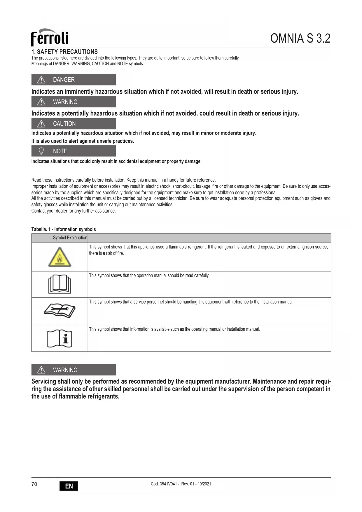
5. GENERAL VIEW AND INTERNAL UNIT HYDRAULIC DIAGRAM
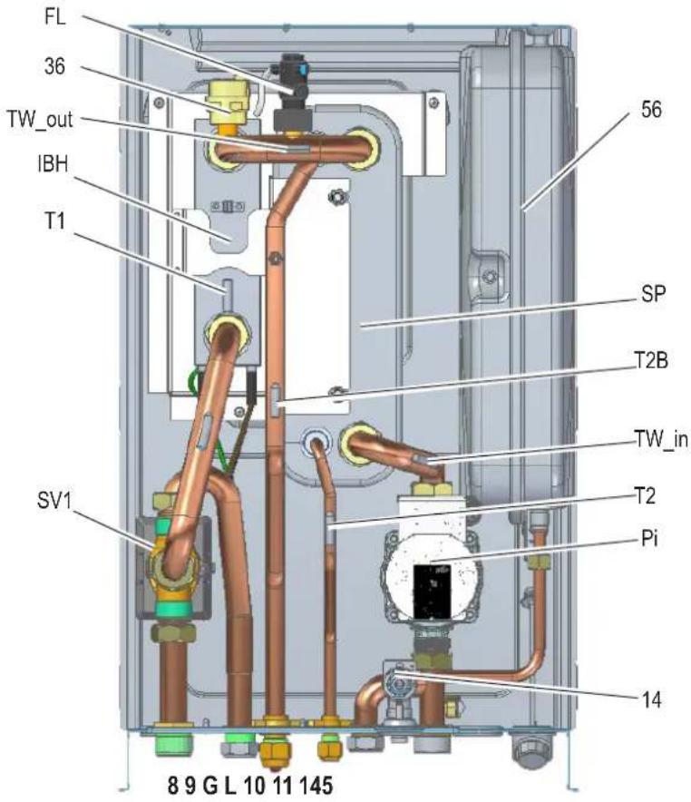
fig. 4 - General view

fig. 5 - Indoor unit hydraulic diagram
LEGEND
8 Plant outlet
9 DHW outlet
10 DHW inlet
11 Plant inlet
14 Safety valve
36 Automatic air vent
56 Expansion vessel
145 Water pressure gauge
FL Flow switch
Gas line
IBH System electrical heater
L Liquid line
Pi Water circulator
SP Plate heat exchanger
SV1 Diverter valve
T1 Heat pump outlet water temperature probe
T2 Heat pump liquid refrigerant temperature probe
T2B Heat pump gas refrigerant temperature probe
TW_in Plate heat exchanger water inlet temperature probe
TW_out Plate heat exchanger water outlet temperature probe
6. SYSTEM EXEMPLARY SCHEMES

7. INSTALLATION
7.1 Inspections on arrival
Upon receipt of the unit it is essential to check that you have received all the material indicated on the accompanying document, and also that it has not been damaged during transport. If so, have the dispatcher ascertain the extent of the damage suffered, alerting our customer management office in the meantime. Only by acting in this way and in a timely manner will it be possible to have the missing material or compensation for damages.
7.1.1 Packing and storing
All machines are packed in cardboard boxes specific for each unit.
The indications required to correctly handle the appliance while storing and installing it are written on the packing.
The storage temperature must be between -25ircC and 55ircC .

NOTE
Do not dispose of the packaging in the environment.
Do not dispose of, leave or leave within the reach of children the packaging material as it may be a potential source of danger.
Once the place in which the unit is to be installed has been chosen (see the relative sections) proceed as follows to unpack the indoor unit.
Installation requirements
- The indoor unit is packed in a box.
- At delivery, the unit must be checked and any damage must be reported immediately to the carrier claims agent.
- Check if all indoor unit accessories are enclosed.
- Bring the unit as close as possible to the final installation position in its original package in order to prevent damage during transport.
- The indoor unit weight is approximately 40kg and should be lifted by two persons.

fig. 6 -
7.1.2 Selecting the installation site and minimum operating area for indoor unit

WARNING
There is flammable refrigerant in the unit and it should be installed in a well-ventilated site. If the unit is installed inside, an additional refrigerant detection device and ventilation equipment must be added in accordance with the standard EN378. Be sure to adopt adequate measures to prevent the unit from being used as a shelter by small animals.
Small animals making contact with electrical parts can cause malfunction, smoke or fire. Please instruct the customer to keep the area around the unit clean.
The equipment is not intended for use in a potentially explosive atmosphere.
- Select an installation site where the following conditions are satisfied and one that meets with your customer's approval.
-Places that are well-ventilated.
- Safe places which can bear the unit's weight and vibration and where the unit can be installed at an even level.
- Places where there is no possibility of flammable gas or product leak.
- Places where servicing space can be well ensured.
- Places where the units' piping and wiring lengths come within the allowable ranges.
- Places where water leaking from the unit cannot cause damage to the location.
- Places where rain can be avoided as much as possible.
- Do not install the unit in places often used as a work space. In case of construction work (e.g. grinding etc.) where a lot of dust is created, the unit must be covered.
- Do not place any object or equipment on top of the unit (top plate)
- Do not climb, sit or stand on top of the unit.
- Be sure that sufficient precautions are taken in case of refrigerant leakage according to relevant local laws and regulations.
- Don't install the unit near the sea or where there is corrosion gas.
The place of installation must be free of powders, flammable objects or materials or corrosive gases.
The unit is designed for wall hanging installation and is equipped as standard with a mounting bracket. The fixing to the wall must guarantee a stable and effective support.

NOTE
For the dismantling of the paneling and for normal maintenance activities the minimum operating spaces must be respected.
Select an installation location where the following conditions are met:
- Place that allows to respect the maximum lengths allowed for pipes, connections to the unit of temperature probes, remote control etc..
- Do not place objects or equipment on top of the unit.
- Make sure that all the precautions and prescriptions foreseen by local laws and regulations regarding possible refrigerant leaks are correctly applied.
- It is advisable to place the boiler for domestic hot water production as close as possible to the indoor unit.

fig. 7 - minimum operating area for indoor unit

CAUTION
The indoor unit should be installed in an indoor water proof place, or the safety of the unit and the operator cannot be ensured.
- The indoor unit is to be wall mounted in an indoor location that meets the following requirements:
- The installation location is frost-free.
- The space around the unit is adequate for serving, see fig. 7.
- The space around the unit allows for sufficient air circulation.
- There is a provision for pressure relief valve blow-off.

CAUTION
When the unit running in the cooling mode, condensate may drop from the water inlet and water outlet pipes. Please make sure the dropping condensate will not result in damage of your furniture and other devices.
The installation surface is a flat and vertical non-combustible wall, capable of supporting the operation weight of the unit.
- All piping lengths and distance have been taken into consideration.
7.2 Minimum plant water content and requirements for DHW boiler (not supplied with the unit)
| Indoor unit technical data 10 16 16T UM | |||||
| Minimum plant water content 15 25 l | |||||
| DHW boiler - minimum surface of the coil(minimum / recommended) | steel | 1,4 / 2,5 1,75 / 4,0 m | 2 | ||
| enamel | 1,7 / 3,0 2,5 / 5,6 m | 2 | |||
| Requirement | Value |
| Maximum allowable piping length between the domestic hot water tank and the indoor unit (only for installations with domestic hot water tank). The temperature probe cable supplied with the indoor unit is 10m in length. | 8m |
7.3 Limits to the length and heigth difference of refrigerant pipes
The length of the refrigerant pipes between the indoor and outdoor units must be as short as possible and is in any case limited by compliance with the maximum height difference values between the units.
Diminution of the difference in height between the units (H1,H2) and of the pipe lengths (L) will limit the load losses, consequently increasing the overall efficiency of the machine.
Comply with the limits given in the following tables.

fig. 8 - Outdoor unit below indoor unit

fig. 9 - Outdoor unit above indoor unit
| Outdoor unit 4 6 8 10 12 14 16 | 12T 14T 16T U | M | |||||||||
| Liquid refrigerant connection | 1/4" | 1/4" | 3/8" | 3/8" | 3/8" | 3/8" | 3/8" | 3/8" | 3/8" | 3/8" | SAE |
| Gas refrigerant connection | 5/8" | 5/8" | 5/8" | 5/8" | 5/8" | 5/8" | 5/8" | 5/8" | 5/8" | 5/8" | SAE |
| Standard refrigerant charge (R32) 1,5,1,5,1,65 1,65 1,84 1,84 1,84 kg | |||||||||||
| Indoor unit | 10 | 16 | 16T | UM | |||||||
| Liquid refrigerant connection | 3/8" (1) | 3/8" (1) | 3/8" 3/8" | 3/8" 3/8" 3/8" 3/8" 3/8" | 3/8" 3/8" SAE | ||||||
| Gas refrigerant connection | 5/8" | 5/8" | 5/8" | 5/8" | 5/8" | 5/8" | 5/8" | 5/8" | 5/8" | 5/8" | SAE |
For matching with outdoor units mod. 4-6 a reduction fitting from 3 / 8 "SAE to 1 / 4 SAE is provided for liquid line 6.35
| Refrigerant pipes | 4 6 8 10 | 12 14 16 12T 14T 16T UMM | |||||||||
| Liquid refrigerant pipe (external diameter) | 6,35 | 6,35 | 9.52 | 9.52 | 9,52 | 9,52 | 9,52 | 9,52 | 9,52 | 9,52 | mm |
| Gas refrigerant pipe (external diameter) | 15,88 | 15,88 | 15,88 | 15,88 | 15,88 | 15,88 | 15,88 | 15,88 | 15,88 | 15,88 | mm |
| Max pipe length with standard refrigerant charge | 15 15 15 | 15 15 15 15 15 | 15 15 | m | |||||||
| Refrigerant charge for each meter more than 15m length | 20 20 38 | 38 38 38 38 38 | 38 38 g/m | ||||||||
| Max length between indoor and outdoor unit | 30 | 30 | 30 | 30 | 30 | 30 | 30 | 30 | 30 | 30 | m |
| Max different in height (H1) | 20 20 20 | 20 20 20 20 20 | 20 20 | m | |||||||
| Max different in height (H2) | 20 20 20 | 20 20 20 20 20 | 20 20 | m | |||||||
Contact our technical department for the required modifications if the units must operate beyond the specifications given above.

NOTE
Refrigerant pipes containing R32 refrigerant which connect refrigerating system components shall not be considered a source of leaked refrigerant for the purpose of evaluating potential for fire or explosion hazard relative to potential ignition sources within the appliance if the piping within the area of the appliance to be evaluated complies with all of the following;
no connecting joints;
no bends with centreline bend radius less than 2,5 times the external pipe diameter;
protected from potential damage during normal operation , service or maintenance.

CAUTION
To prevent the refrigerant piping from oxidizing inside when welding, it is necessary to charge nitrogen, or oxide will chock the circulation system.
Pressured nitrogen [4.3MPa (43bar) for R32] should be used in the airtight testing.
Tighten high/low pressure valves before charging pressured nitrogen.
Charge pressure nitrogen from the connector on the pressure valves.
The airtight testing should never use any oxygen, flammable gas or poisonous gas.
7.4 Refrigerant connections
Comply with the following indications when connecting the refrigerant pipes:
- Make sure that the refrigerant pipes can withstand the refrigerant maximum pressure (PS= 4,3MPa).
Make sure there is no any dirt or water before connection the piping to the outdoor and indoor units. - Wash the pipes with high pressure nitrogen, never use refrigerant of outdoor unit.
Match the ends of the previously flared pipe with those of the connections on the indoor units (see part. L e G "fig. 3 - dimensional data and connections" a pagina 87). - Tighten the union by hand and then torque it with the aid of an adequate wrench.


fig. 10 -
To the outdoor unit
- Match the ends of the pipe previously flared with those of the taps on the outdoor unit.
- Screw the fitting by hand and then tighten it with a suitable wrench.

fig.11-
The protective cap is a one-time part, it can not be reused. In case it is removed, it should be replaced with a new one.
| Outer diam. | Tightening torque (Nm) | Additional tightening torque (Nm) |
| Ø 6.35 | 15 | 16 |
| Ø 9.52 | 25 | 26 |
| Ø 15.88 | 45 | 47 |

CAUTION
To prevent the refrigerant piping from oxidizing inside when welding, it is necessary to charge nitrogen, or oxide will chock the circulation system.
7.4.1 Airtight test and leakage detection
Before setting the system in a vacuum, it is advisable to make sure that the refrigerant circuit is tight, including the connecting joints between the pipes and the indoor unit. Proceed in the following way:
- With the service valves of the outdoor unit completely shut, remove the cap from the service tap (part 1 - fig. 12) and the union (part 2 - fig. 12) of the gas valve (the larger one)
- Connect the service valve to a manometric unit plus oxygen free nitrogen (OFN) bottle.
- Pressurize the system to a maximum 43 bar (44kg / cm2) using the oxygen free nitrogen (OFN) in the bottle.
- Use liquid soap to check that the joints are tight and without leaks.
Keep the bottle vertical during the pressurizing operation to prevent liquid nitrogen from infiltrating into the system!
-
Check all the connection joints on both the outdoor and indoor units to make sure that they are tight. Bubbles will form if leaks are present. If bubbles appear, make sure that the unions have been tightened and that the flares are the right shape.
-
Wipe off the liquid soap with a rag.
- Reduce the pressure of the nitrogen in the circuit by loosening the charge pipe from the bottle.
- Having reduced the pressure, disconnect the nitrogen bottle.

CAUTION
The airtight testing should never use any oxygen, flammable gas or poisonous gas.

fig. 12 - Airtight test and leakage detection
7.4.2 Air purge with vacuum pump
Air and humidity in the cooling circuit impair the operation of the unit with effects such as: increased pressure, reduced efficiency, formation of ice on the capillary and subsequent blockage of the same, corrosion in the circuit.
This is why a vacuum must be created in the connection pipes and indoor unit. Proceed in the following way:
- Connect the previously described charging pipe to the vacuum pump.
- Turn on the relative knob on the monometric unit to allow the pump to access the cooling circuit.
- Wait until the pressure level measured by the pressure gauge is around 3mmHg (400 Pa)
- As soon as the required vacuum value is reached, shut the connection cock and stop the vacuum pump.

fig. 13 - Air purge with vacuum pump
Note
OU = Outdoor unit
IU = Indoor unit
7.4.3 Heat insulation
In order to avoid the release of cold or heat from the connecting pipeline to the external environment during the operation of the equipment, please take effective insulation measures for the gas pipe and liquid pipe separately.
1) The gas side pipe should use closed cell foamed insulation material, which the fire-retardant is B1 grade and the heat resistance over 120ircC .
2) When the external diameter of copper pipe ≤ 12.7mm , the thickness of the insulating layer at least more than 15mm ; When the external diameter of copper pipe ≥ 15.9mm , the thickness of the insulating layer at least more than 20mm .
3) Please use heat-insulating materials to do the heat insulation without clearance for the connecting parts of the indoor unit pipes.
7.4.4 Refrigerant amount to be added
Calculate the added refrigerant according to the diameter and the length of the liquid side pipe of the outdoor unit/indoor unit connection.
If the length of the liquid side pipe is less than 15 meters it is no need to add more refrigerant, so than calculating the added refrigerant the length of the liquid side pipe must subtract 15 meters.
| Refrigerant to be added System model | Total liquid pipe length L (m) | ||
| ≤15m >15m | |||
| Total additional refrigerant | 4/6 0g (L-15)×20g | ||
| 8/10/12/14/16/12T/14T/16T 0g (L-15)×38g | |||
7.5 Hydraulic connections

CAUTION
The safety valve outlet must be connected to a funnel or collection pipe to prevent water spurting onto the floor in case of overpressure in the heating circuit. Otherwise, if the discharge valve cuts in and floods the room, the manufacturer cannot be held liable.

NOTE
The water may drip from the discharge pipe of the pressure-relief device and that this pipe must be left open to the atmosphere.
The pressure-relief device is to be operated regularly to remove lime deposits and to verify that it is not blocked.
Before installation, flush all the pipes of the system thoroughly to remove any residuals or impurities that could affect proper operation of the unit.
In case of replacement of generators in existing installations, the system must be completely emptied and cleaned of any sludge and pollutants. For that purpose only use suitable guaranteed products for heating systems (see next section), that do not harm metals, plastics or rubber.
The manufacturer declines any liability for damage caused to the generator by failure to properly clean the system.

NOTE
Since the joints of the unit are made of brass and brass is an easily deformable material, using appropriate tools for connecting the hydraulic circuit, inappropriate tools will cause damage to the pipes.
Make the connections to the respective points (see "fig. 3 - dimensional data and connections" a pagina 87) and to the symbols given on the unit.
7.5.1 Antifreeze plant, antifreeze fluids, additives and inhibitors
When necessary, antifreeze fluids, additives and inhibitors can be used only if the manufacturer of such fluids or additives guarantees that they are suitable and do not cause damage to the exchanger or other components and/or materials of the boiler/heat pump and plant. Do not use generic antifreeze fluids, additives or inhibitors that are not specific for use in heating systems and compatible with the materials of the boiler/heat pump and plant.
Only use conditioners, additives, inhibitors and antifreeze liquids declared by the producer suitable for use in heating systems and that do not cause damage to the heat exchanger or other components and/or materials of the boiler and plant.
Chemical conditioners must ensure complete deoxygenation of the water, contain specific protection for yellow metals (copper and its alloys), anti-fouling agents for scale, neutral pH stabilizers and, in low-temperature systems, specific biocides for use in heating systems.
Recommended chemical conditioners:
SENTINEL X100 and SENTINEL X200
FERNOX F1 and FERNOX F3
7.5.2 Water filter
It is mandatory to install at the inlet of the unit the Y-shape water filter (supplied with the unit).

NOTE
The presence of deposits on the indoor unit exchange surfaces due to non-compliance with the above requirements will involve non-recognition of the warranty.
7.5.3 Tips for a successful installation
For a correct design and installation of the hydraulic plant comply the local laws governing safety matters and sound.
The following information is suggestion for a correct installation of the unit.
- Before connecting the unit to the plant wash adequately the pipes using clean water, filling and emptying and cleaning the filters.
- Only after that proceed connecting the unit to the plant; this operation is crucial to ensure proper start-up without the need to have repeated stops to clean the filter, with the possible risk of damage to heat exchangers and other components.
- Check by qualified personnel the quality of the water or of the mixture used; avoid the presence of inorganic salts, biological load (seaweeds, etc.) suspended solids, dissolved oxygen and the pH. Water with inadequate characteristics can cause a pressure drop increase due to a rapid fouling of the filter, energy efficiency decrease and corrosive symptom increase that can damage the unit.
The pipes must have the least possible number of bends to minimize load losses and must be adequately supported in order to prevent the connections of the unait from being excessively stressed. - Install on-off valves near components that need to be serviced to isolate them when maintenance work needs to be done and to allow them to be replaced without having to discharge the plant.
- Before isolating the pipes and charging the system, carry out preliminary inspections to make sure that there are no leaks.
- Isolate all the chilled water pipes to prevent condensation from forming along the pipes themselves. Make sure that the material used is the steam barrier type, failing this, cover the insulation with an appropriate protection. Also make sure that the air venting valves can be accessed through the insulation.
The circuit can be maintained under pressure using an expansion vessel (present in the unit) and a pressure reducer. A system filling device can be used that automatically, under a pressure value, provides for the loading and maintenance of the desired pressure. - Check that all plant components are able to withstand the maximum static pressure (depending on the height of the building to be served).

NOTE
If there is no glycol in the system (antifreeze) or if the unit is not able to remain electrically powered for possible blackouts, in order to avoid possible icing problems, empty the water during winter.
The unit is only to be used in a closed water plant. Application in an open water circuit can lead to excessive corrosion of the water piping.
Water connections must be made in accordance with the outlook diagram delivered with the unit, with respect to the water intake and water outlet.
If air, moisture or dust gets in the water circuit, problems may occur. Therefore, always take into account the following when connecting the water circuit:
Use clean pipes only.
Hold the pipe end downwards when removing burrs
Cover the pipe end when inserting it through a wall so that no dust and dirt enter.
Use a good thread sealant for sealing the connections. The sealing must be able to withstand the pressures and temperatures of the plant.
When using non-brass metallic piping, make sure to insulate both materials from each other to prevent galvanic corrosion. Never use Zn-coated parts in the water circuit. Excessive corrosion of these parts may occur as copper piping is used in the unit's internal water circuit.
7.5.4 Filling with water
- Connect the water supply to the fill valve and open the valve.
- Make sure the automatic air purge valve is open (at least 2 turns).
- Fill with water until the manometer indicates a pressure of approximately 2.0 bar. Remove air in the circuit as much as possible using the air purge valves. Air present in the water circuit might cause malfunctioning of the backup heater.

NOTE
During filling, it might not be possible to remove all air in the system. Remaining air will be removed through the automatic air purge valves during the first operating hours of the system. Topping up the water afterwards might be required. The water pressure indicated on the manometer will vary depending on the water temperature (higher pressure at higher water temperature). However, at all times water pressure should remain above 0.3 bar to avoid air entering the circuit.
The unit is only to be used in a closed water plant. Application in an open water circuit can lead to excessive corrosion of the water piping:
Never use Zn-coated parts in the water circuit. Excessive corrosion of these parts may occur as copper piping is used in the unit's internal water circuit.
When using a 3-way valve or a 2-way valve in the water circuit. The recommended maximum changeover time of the valve should be less than 60 seconds.
7.5.5 Water circuit anti-freeze protection
All internal hydronic parts are insulated to reduce heat loss. Insulation must also be added to the field piping.
The software contains special functions using the heat pump and backup heater to protect the entire system against freezing. When the temperature of the water flow in the system drops to a certain value, the unit will heat the water, either using the heat pump, the electric heating tap, or the backup heater. The freeze protection function will turn off only when the temperature increases to a certain value.
In event of a power failure, the above features would not protect the unit from freezing.

CAUTION
When the unit is not running for a long time, make sure the unit is powered on all the time, if you want to cut off the power, the water in the system pipe needs to be drained clean, avoid the pump and pipeline system be damaged by freezing. Also the power of the unit needs to be cut off after water in the system is drained clean.
- The unit might drain-off too much water through the pressure relief valve.
Water quality should be complied with EN 98/83 EC Directives. - Detailed water quality condition can be found in EN 98/83 EC Directives.
7.5.6 Water piping insulation
The complete water circuit including all piping, water piping must be insulated to prevent condensation during cooling operation and reduction of the heating and cooling capacity as well as prevention of freezing of the outside water piping during winter. The insulation material should at least of B1 fire resistance rating and complies with all applicable legislation. The thickness of the sealing materials must be at least 13mm with thermal conductivity 0.039 W/mK in order to prevent freezing on the outside water piping.
If the outdoor ambient temperature is higher than 30ircC and the humidity is higher than RH 80%, then the thickness of the sealing materials should be at least 20 mm in order to avoid condensation on the surface of the seal.
7.6 Electrical connections
7.6.1 Electrical data
Tabella. 5 - Electrical data
| Indoor unit MOD. | 10 16 16T | |||
| Power input " 220-240V 50 Hz 220-240V 50 Hz 380" | 415 3+N+PE 50 Hz | |||
| Max current input A 13 13 10 | ||||
| Automatic circuit breaker A 16 16 16 | ||||
| Power cable section mm | 2 | 3x1,5 | 3x1,5 | 5x1,5 |
The customer must install the automatic circuit breaker.
| Communication cable between indoor and outdoor unit | MOD. | 10 16 16T | ||
| Wiring size (shielded cable) | mm² | 3x0,75 | ||
Example of basic connections for a single phase system


WARNING
A main switch or other means of disconnection, having a contact separation in all poles, must be incorporated in the fixed wiring in accordance with relevant local laws and regulations.
Switch off the power supply before making any connections.
Use only copper wires. Never squeeze bundled cables and make sure they do not come in contact with the piping and sharp edges. Make sure no external pressure is applied to the terminal connections.
All field wiring and components must be installed by a licensed electrician and must comply with relevant local laws and regulations.
The field wiring must be carried out in accordance with the wiring diagram supplied with the unit and the instructions given below.
Be sure to use a dedicated power supply. Never use a power supply shared by another appliance.
Be sure to establish a ground. Do not ground the unit to a utility pipe, surge protector, or telephone ground. Incomplete grounding may cause electrical shock.
Be sure to install a ground fault circuit interrupter (30 mA). Failure to do so may cause electrical shock.
Be sure to install the required fuses or circuit breakers.

WARNING
Cut off all power supply—i.e. unit power supply and backup heater and domestic hot water tank power supply (if applicable) — before removing front panel. Parts inside the unit may be hot.

NOTE
The ground fault circuit interrupter must be a high- speed type breaker of 30mA (< 0.1s)
This unit is equipped with an inverter. Installing a phase advancing capacitor not only will reduce the power factor improvement effect, but also may cause abnormal heating of the capacitor due to high-frequency waves. Never install a phase advancing capacitor as it could lead to an accident.

WARNING
Before any operation which requires removing the cover, disconnect the indoor unit from the power supply through the main switch.

DANGER
Do not touch the electrical components in any case with the closed main switch! There is the risk of electric shock with risk of injury or death!
The appliance must be connected to an effective earthing system, as provided for by the current safety regulations. Have the efficiency and suitability of the earthing system checked by professionally qualified personnel, the manufacturer is not responsible for any damage caused by lack of earthing of the system.
The indoor unit is prewired and provided with a three-pole cable or five-pole cable, without a plug, for connection to the electric line. The connections to the grid must be made with a permanent connection and equipped with a switch (2 poles or 4 poles) whose contacts have a minimum opening of at least 3mm , interposing an automatic circuit breaker (refer to "Tabella. 5 - Electrical data" a pagina 97) between the indoor unit and the line.
For single-phase units (mod. 10 and 16)
Make sure to respect the polarities (LINE: brown wire / NEUTRAL: blue wire / GROUND: yellow-green wire) in the connections to the electric line.
For three-phase units (mod. 16T)
Make sure to respect the polarities (L1-L2-L3 - N - PE) in the connections to the electric line.

DANGER
The unit's supply cable MUST NOT BE REPLACED BY THE USER. If the cable gets damaged, turn the unit off and have the cable replaced only by professionally qualified personnel. In case of replacement, only use cable "HAR H05 VV-F" 3 × 0.1.5 mm2 (mod. 10 and 16) or 5 × 1.5 mm2 (mod. 16T) with a max external diameter of 11 mm .
7.6.2 How to access to the electric box
- To dismount the front panel of the indoor unit:
- Partially unscrew the screws A (see "fig. 14 - front panel dismounting").
- Pull the panel B out and release it from the upper fixings (see "fig. 14 - front panel dismounting").
- Make the connections referring to the functional electrical diagram present in this manual.
- Proceed in reverse order to reassemble the front panel. Make sure that it is correctly attached to the upper fixing and completely resting on the side panels. The head of the screw "A", once tightened, must not be underneath the lower bending stop (see "fig. 15 - bottom screws mounting").

fig. 14 - front panel dismounting


fig. 15 - bottom screws mounting

fig. 16 - view without front panel

fig. 17 - view without front panel

fig. 18 - how to unlock the electric box

fig. 19 - how to rotate the electric box
To access to the terminals of the indoor unit:
- unscrew the two screws (part. 1 - fig. 16) under the electrical box
- unscrew the upper screw (part. 2a - fig. 17)
- catch the electric box, and unlock (fig. 18)
- rotate forward (fig. 19)
- remove the back metal sheet (part. 3 - fig. 19) that is fixed with 2 screws (part. 4 - fig. 19)
NB
It is possible to remove the back locking bracket (part. 2 - fig. 17) unscrewing the screw (part. 2b - fig. 17).
Legend:
A Display panel and keyboard (fig. 16)
B Electronic hydronic board (fig. 20)
C Safaty thermal cut-out for single phase electrical heater with manual reset button (part. C1 fig. 20)
D Safety thermal cut-out for three phase electrical heater with manual reset button (part. D1 fig. 20)

D
fig. 20 - internal view of the electric box
7.6.3 User connections
All the connections have to be done on the terminals of the hydronic board placed in the electric box.

Hydronic board
fig. 21 - Hydronic board
| Order | Port Code Assembly Unit Note | |||
| 1 | CN21 | POWER | Power supply to hydronic board | B |
| 2 | S3 | / | Rotary dip switch | / |
| 3 | DIS1 | / | Digital display | / |
| 4 | CN5 | GND | Ground to hydronic board | B |
| 5 | CN28 | PUMP | Power supply to internal water pump Pi | B |
| 6 | CN25 DEBUG Port for IC programming | / | ||
| 7 | S1, S2, S4 / Dip switch | / | ||
| 8 | CN4 USB Port for USB programming | / | ||
| 9 | CN8 FS Connection to internal water flow switch | / | ||
| 10 | CN6 | T2* | Port for temperature probe of refrigerant liquid side temperature of indoor unit (heating mode) | B |
| T2B* | Port for temperature probe of refrigerant gas side temperature of indoor unit (heating mode) | B | ||
| TW_in* | Port for temperature probe of inlet water temperature of plate heat exchanger | B | ||
| TW_out* | Port for temperature probe of outlet water temperature of plate heat exchanger | B | ||
| T1* | Port for temperature probe of final outlet water temperature of indoor unit | B | ||
| 11 | CN24 | Tbt1 | Port for temp. sensor probe in the plant tank | A |
| 12 | CN16 | Tbt2 | Reserved | / |
| 13 | CN13 | T5 | Port for temp. sensor probe in the DHW boiler | A |
| 14 | CN15 | Tw2 | Port for outlet water for zone 2 temp. probe probe | A |
| 15 | CN18 | Tsolar** | Port for solar panel temp. sensor | A |
| 16 | CN17 | PUMP_BP | PWM signal to internal water pump Pi | B |
| 17 | CN31 | HT | Control port for room thermostat (heating mode) | 1 |
| COM | Power port for room thermostat | 1 | ||
| CL | Control port for room thermostat (cooling mode) | 1 | ||
| 18 | CN35 | SG | Port for smart grid (grid signal) | 1 |
| EVU | Port for smart grid (photovoltaic signal) | 1 | ||
| 19 | CN36 | M1 M2 | Reserved | / |
| T1 T2 | Reserved | / | ||
| 20 | CN19 | P Q | Reserved | / |
| 21 | CN14 | AB X Y E | Port for communication with the display panel | B |
| Order Fort Code Assembly unit Note | |||||
| 22 CN30 | 1 | A | Reserved / | ||
| 2 | B | ||||
| 3 | X | ||||
| 4 | Y | ||||
| 5 | E | ||||
| 6 | P | 3 Wires for connection with outdoor unit /7 Q | |||
| 8 | E | ||||
| 9 | H1 | Reserved / | |||
| 10 H2 | |||||
| 23 CN7 | 26 R2 | Compressor run (the contact is closed when the compressor is working) 1 | |||
| 30 R1 | |||||
| 31 | DFT2 | Defrost run (the contact is closed when the defrost is active) | 1 | ||
| 32 | DFT1 | ||||
| 25 HT | Reserved | 2 | |||
| 29 | N | ||||
| 27 | AHS1 | Gas boiler (the contact is closed when the gas boiler is request) | 1 | ||
| 28 | AHS2 | ||||
| 24 | CN11 | 1 SL1 | Reserved / | ||
| 2 SL2 | |||||
| 3 | H | Room thermostat input (high voltage) | 2 | ||
| 4 | C | ||||
| 15 | L1 | ||||
| 5 | 1ON | SV1 (3-way diverter valve) plant / DHW B | |||
| 6 | 1OFF | ||||
| 16 | N | ||||
| 7 | 2ON | SV2 (3-way valve) heat / cool | 2 | ||
| 8 | 2OFF | ||||
| 17 | N | ||||
| 9 | P_c | Zone2 pump | 2 | ||
| 21 | N | ||||
| 10 | P_o | Outside circulation pump / zone 1 pump | 2 | ||
| 22 | N | ||||
| 11 | P_s | Solar panel pump | 2 | ||
| 23 | N | ||||
| 12 | P_d | DHW boiler recirculation pump | 2 | ||
| 24 | N | ||||
| 13 | TBH | DHW electric heater | 2 | ||
| 16 | N | ||||
| 14 | IBH1 | Internal backup heater 1 | B | ||
| 17 | N | ||||
| 18 | N | SV3 mixing (3-way valve zone 2) | 2 | ||
| 19 | 3ON | ||||
| 20 | 3OFF | ||||
| 25 | CN2 | TBH_FB | Port for automatic circ. breaker of TBH (shorted in default) | / | |
| 26 | CN1 | IBH1/2_FB | Port for automatic circ. breaker of IBH (shorted in default) | / | |
| 27 | CN22 | IBH1 | Control port for internal backup heater 1 | / | |
| IBH2 | Reserved / | ||||
| TBH | Control port for DHW boiler electrical heater | / | |||
| 28 | CN41 | HEAT8 | Reserved / | ||
| 29 | CN40 | HEAT7 | Reserved / | ||
| 30 | CN42 | HEAT6 | Reserved / | ||
| 31 | CN29 | HEAT5 | Reserved / | ||
NOTES:
A: With accessory Temperature Probe. All these temp. probes can be used or not as a function of the type of the plant served by the unit.
B: Internal connections, it means that these terminals are used for the management of the indoor unit.
1: Dry contact without voltage.
2: Port provide 220-240VAC voltage. If the current of load is < 0.2A , load can connect to the port directly. If the current of load is >=0.2A , the AC contactor is required to supply for the load.
| Voltage | 220-240VAC |
| Maximum running current (A) | 0.2 |
| Wiring size (mm2) | 0.75 |
Connect the cable to the appropriate terminals as shown in the following pictures.
Fix the cable reliably and provide to pass the cable through the appropriate cable gland (refer to "dimensional data and connections" a pagina 87.

P o - For outside circulation pump or water pump zone 1
fig.22 -

P s - Water pump of the solar circuit
fig.25 -

P c - Water pump of zone 2
fig.23 -

SV2 - 3-way diverter valve for heat/cool
fig.26-

Pd-DHW recirculation pump
fig.24-
| Terminals | ||
| Mode | 7 (2ON) | 8 (2OFF) |
| Heat | 230V | 0V |
| Cool | 0V | 230V |
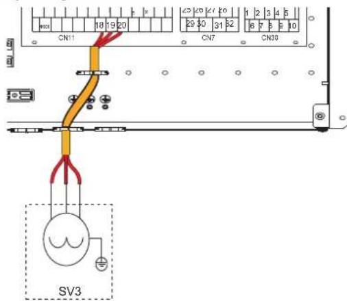
SV3 - 3-way mixing valve for zone 2
fig.27-

TBH - Electrical heater for DHW boiler
fig.28-
H-L1-C - For room thermostat (high voltage)
There are three methods for connecting the thermostat.
- Room thermostat method A (mode set control)
To activate this function set the service parameter 6.1 "Room thermostat" = 1 (mode setting) refer "9.2 Service parameters table" a pagina 117.
A.1 When unit detect voltage is 230VAC between C and L1, the unit operates in the cooling mode.
A.2 When unit detect voltage is 230VAC between H and L1, the unit operates in the heating mode.
A.3 When unit detect voltage is 0VAC for both side(C-L1, H-L1) the unit stop working for space heating or cooling.
A.4 When unit detect voltage is 230VAC for both side(C-L1, H-L1) the unit working in cooling mode.

fig.29
- Room thermostat method B (one zone control)
To activate this function set the service parameter 6.1 "Room thermostat" = 2 (one zone) refer "9.2 Service parameters table" a pagina 117.
B.1 When unit detect voltage is 230VAC between H and L1, unit turns on.
B.2 When unit detect voltage is 0VAC between H and L1, unit turns off.

fig.30 -
- Room thermostat method C (double zone control)
To activate this function set the service parameter 6.1 "Room thermostat" = 3 (double zone) refer "9.2 Service parameters table" a pagina 117.
C.1 When unit detect voltage is 230VAC between H and L1, zone1 turns on. When unit detect voltage is 0VAC between H and L1, zone1 turns off.
C.2 When unit detect voltage is 230VAC between C and L1, zone2 turns on according to climate temp curve. When unit detect voltage is 0V between C and L1, zone2 turns off.
C.3 When H-L1 and C-L1 are detected as 0VAC, unit turns off.
C.4 when H-L1 and C-L1 are detected as 230VAC, both zone1 and zone2 turn on.

fig.31-
HT-COM-CL - Room thermostat (Low voltage)
There are three methods for connecting the thermostat.
- Room thermostat method A (mode set control)
To activate this function set the service parameter 6.1 "Room thermostat" = 1 (mode setting) refer "9.2 Service parameters table" a pagina 117.
A.1 When unit detect voltage is 12VDC between CL and COM, the unit operates in the cooling mode.
A.2 When unit detect voltage is 12VDC between HT and COM, the unit operates in the heating mode.
A.3 When unit detect voltage is 0VDC for both side(CL-COM, HT-COM) the unit stop working for space heating or cooling.
A.4 When unit detect voltage is 12VDC for both side(CL-COM, HT-COM) the unit working in cooling mode.

fig.32 -
- Room thermostat method B (one zone control)
To activate this function set the service parameter 6.1 "Room thermostat" = 2 (one zone) refer "9.2 Service parameters table" a pagina 117.
B.1 When unit detect voltage is 12VDC between HT and COM, unit turns on.
B.2 When unit detect voltage is 0VDC between HT and COM, unit turns off.

fig.33 -
- Room thermostat method C (double zone control)
To activate this function set the service parameter 6.1 "Room thermostat" = 3 (double zone) refer "9.2 Service parameters table" a pagina 117.
C.1 When unit detect voltage is 12VDC between HT and COM, zone1 turn on. When unit detect voltage is 0VDC between HT and COM, zone1 turn off.
C.2 When unit detect voltage is 12VDC between CL and COM, zone2 turn on according to climate temp curve. When unit detect voltage is 0V between CL and COM, zone2 turn off.
C.3 When HT-COM and CL-COM are detected as 0VDC, unit turn off.
C.4 when HT-COM and CL-COM are detected as 12VDC, both zone1 and zone2 tum on.

fig.34 -

NOTE
The wiring of the thermostat should correspond to the settings of the user interface.
Power supply of machine and room thermostat must be connected to the same Neutral Line.
Zone 2 can only operate in heating mode, When cooling mode is set on user interface and zone1 is OFF, "CL" in zone2 closes, system still keeps 'OFF'. While installation, the wiring of thermostats for zone1 and zone2 must be correct.

AHS1. AHS2 - For additional heat source control (GAS BOILER)
fig.35-
Photovoltaic input and smart grid operation:
- When EVU input is closed, the unit operates as below:
DHW mode turn on, the DHW setting temperature will be changed to 70ircC automatically, and the TBH (electrical heater of DHW boiler) will be activated if : T5 (DHW boiler temperature) < 69ircC . The unit operates in cooling/heating mode as the normal logic. - When EVU input is open and SG input is closed, the unit operates normally.
- When EVU input is open and SG input is open, the DHW mode is off, the TBH is off, the disinfect function is off. The max running time for cooling/heating is "Smart Grid Run Time Set", then unit will be off.
The parameter "Smart Grid Run Time Set" is settable by user menu (refer to "8.5 User menu" a pagina 109.
| EVU INPUT | SG INPUT | Operation |
| closed | open | photovoltaic operation |
| closed | closed | photovoltaic operation |
| open | closed | normal operation |
| open | open | smart grid operation |
EVU-SG - Photovoltaic input and smart grid
The unit has smart grid function, there are two ports on PCB to connect SG signal and EVU signal as following.

fig.36 -
8. USER INTERFACE
The user interface consists of 7 keys and a display with dot matrix technology.
8.1 Key function description

User interface Key function description
fig.37-
| Key ID Function Functional details | ||
| SW1 UP On | MAIN it selects / | rolls up / down between DHW - PLANT or DHW - IMP. Z1 -IMP. Z2 if the 2nd zone is enabled Within the menu, scrolls up / down the menu lines |
| SW2 DOWN | ||
| SW3 MENU | / CONFIRM Access to the general menu and confirm parameter value if modified | |
| SW4 BACK | Return to previous screen | |
| SW5 ON/OFF Shutdown | - short press - turns on/off DHW or Z1 or Z2 depending on the selection - pressure>5 sec. turn on/off everything (DHW-Z1-Z2) | |
| SW6 UP VALORE - Increase the set temperature DHW-Z1-Z2 | - Increase the value of the parameter selected in the menu | |
| SW7 DOWN | VALORE - Decreases | DHW-Z1-Z2 set temperature - Decreases the value of the parameter selected in the menu |
8.2 Meaning of display icons
| 01-01-2021 01:07 | 01-01-2021 01:00 | 01-01-2021 01:04 |
| 1°2'3'4'5" | 1°2'3'4'5" | 1°2'3'4'5" |
| 5°6'7'8" | 1°6'7'8" | 1°6'7'8" |
| 10°9'11" | 10°9'11" | 10°9'11" |
| 12°22" | 12°22" | 22° |
| 13° | 13° | 20° |
| 14°33" | 14°33" | 22° |
| 15° | 15° | 33° |
| Index | Icon | Description | Function | Additional Notes |
| 1 | ◎ | Water circulator | It activates when the pump is active | |
| 2 | ◎ | compressor | It activates when the compressor is active | |
| 3 | ◎ | Supplementary heating source (boiler) | It is activated when the boiler is active | |
| ◎ | Electric heater | It is activated when the electric heater is active | ||
| 4 | ◎ | External temperature | Allows the external air temperature to be displayed. | |
| Index Icon Description | Function Additional Notes | |||
| 5 timer It is activated when one of the timed functions | is active | - | ||
| 6 | ∅ | Eco function | It is activated when the ECO function is active | It can be active 24 hours a day or based on a scheduled event. |
| 7 | # | Photovoltaic PV | It is activated when in-dig FV = closed | They appear only if the smart-grid function is enabled. The icons appear according to the status of the in-digs. EVU and SG hydronic board. |
| # | Smart grid SG It is activated when | in-dig SG = closed | ||
| # | Maximum energy consumption Appears when in-dig EVU and SG = both open. | |||
| 8 | # | Antifreeze | It is activated when the antifreeze is in progress | Shared display position Appears depending on the active function. Priority index In case of contemporaneity 1 antifreeze 2 defrost 3 silent mode |
| # | Defrost | It is activated when defrosting is in progress | ||
| # | Silent mode | Activates when silent mode is in progress | ||
| 9 | # | Healthcare symbol | DHW mode. | if crossed out = disabled |
| 10 | # | Anti-legionella | Anti-legionella in progress | |
| 11 | # | Solar panels | It is activated when the solar thermal panel is in operation | Shared display position. They appear depending on the active function. It is not possible contemporaneity. |
| # | DHW boiler electric heater | It is activated when the DHW boiler electric heater is in operation. | ||
| 12 | 22°C | Temper. DHW - DHW set point | View temp. DHW tank probe (if present) | View the setup. DHW while editing. If DHW = off, OFF appears instead of the temperature. |
| 13 | # | Heating symbol | Heating mode active | Shared display position. They appear depending on the active function. |
| # | Cooling symbol | Cooling mode active | ||
| 14 | # | Vacation mode | Active vacation period | |
| 15 | 33°C | - Water flow set point - Zone 1 delivery set point - Zone 2 delivery set point | -Single-zone water flow setpoint - without Z1-Z2 alongside. - Zone 1 water flow setpoint if a has Z1 next to it - Zone 2 water flow setpoint if a has Z2 next to it | If it is configured only in single zone, it will not have Z1 / Z2 alongside. If double zone is configured, it will always have either Z1 or Z2 next to it to indicate which zone the displayed value refers to. If single zone or Z1 or Z2 = off, OFF appears |
| 16 | Z1 | Zone 1 indicator | appears when zone management is enabled and is always present next to the set point (15) | Indicates that zone 1 set point is displayed. Not present if double zone is not enabled. |
| 17-18-19 | # | Selection indicator between DHW-Z1-Z2 to modify the set point | Indicates the set point selected for modification | When it appears next to a set point, it means that it can be changed. It can be moved by acting on the SW1-SW2 keys |
| 20 | Z2 | Zone 2 indicator | appears when zone management is enabled and is always present next to the set point (15) | Indicates that the zone 2 set point is displayed. Not present if double zone is not enabled. |
8.3 Switching ON and OFF DHW and plant
Switching on or off (ON / OFF) is done with the SW5 key.
When a mode is turned off, OFF appears in place of the current display.
When a mode is turned on, the current display appears.
There are two possibilities of switching on / off: for single function and general.
Single function power off / on:
- DHW is selected and with 1sec pressure. of OFF switches off / on DHW only
- One-zone selection is selected with 1sec pressure. of OFF switches off / on DHW only
- Z1 is selected and with 1sec pressure. of OFF turns off / on only Z1
- Z2 is selected and with 1sec pressure. of OFF turns off / on only Z2
General shutdown:
With a long OFF pressure> 3 sec of OFF, all DHW and zones are switched on or off.
8.4 HEAT, COOL and DHW setpoint settings
| DHW set point (min 30°C, max 60°C) To modify the DHW set point, proceed as follows: • press the SW1 / SW2 buttons to select the set point • press the SW6 / SW7 keys to modify the set point • confirm the modified value with SW3 key | 01-01-2021 01:87 02 33° |
| Single zone set point (Cool mode min 5°C, max 25°C - Heat mode min 25°C, max 65°C) To modify the single zone set point, proceed as follows: • press the SW1 / SW2 buttons to select the set point • press the SW6 / SW7 keys to modify the set point • confirm the modified value with SW3 key | 01-01-2021 01:87 02 33° |
| Zone Z1 set point (Cool mode min 5°C, max 25°C - Heat mode min 25°C, max 65°C) To modify the set point of zone Z1 proceed as follows: • press the SW1 / SW2 buttons to select the set point • press the SW6 / SW7 keys to modify the set point • confirm the modified value with SW3 key | 01-01-2021 01:87 02 33° |
| Zone Z2 set point (Cool mode min 5°C, max 25°C - Heat mode min 25°C, max 65°C) To modify the set point of zone Z2 proceed as follows: • press the SW1 / SW2 buttons to select the set point • press the SW6 / SW7 keys to modify the set point • confirm the modified value with SW3 key | 01-01-2021 01:87 02 33° |
Press the SW3 key to access the user menu which is structured on several levels as indicated in the following table:
8.5 User menu
| Menu Level 1 | Menu Level 2 | Menu Level 3 | Menu Level 4 | Menu Level 5 | Description | Lower limit | Upper limit | Resolu-tion | Unit of measure | Default value |
| Operation Mode | Heat / Cool ---- | 2: Cooling, 3: Heating, 0: Invalid | 2 3 1 Label 3 | |||||||
| Preset TempCool | Preset TempCool | Monday | Event 1 Enabled y/in Enables the Event YES NO // NO | |||||||
| Event 2 | Time | Start time hh.mm | 00.00 | 23.59 | 1 min | hh:mm | 00.00 | |||
| Event 3 | Temperature | Water temperature setpoint | min* | max* | 1 | °C | 8 | |||
| Event 4 | ||||||||||
| Event 5 | ||||||||||
| Event 6 | ||||||||||
| Tuesday | Event 1 Enabled y/in Enables the Event YES NO // NO | |||||||||
| Event 2 | Time | Start time hh.mm | 00.00 | 23.59 | 1 min | hh:mm | 00.00 | |||
| Event 3 | Temperature | Water temperature setpoint | 5 | 25 | 1 | °C | 8 | |||
| Event 4 | ||||||||||
| Event 5 | ||||||||||
| Event 6 | ||||||||||
| Wednesday | Event 1 Enabled y/in Enables the Event YES NO // NO | |||||||||
| Event 2 | Time | Start time hh.mm | 00.00 | 23.59 | 1 min | hh:mm | 00.00 | |||
| Event 3 | Temperature | Water temperature setpoint | 5 | 25 | 1 | °C | 8 | |||
| Event 4 | ||||||||||
| Event 5 | ||||||||||
| Event 6 | ||||||||||
| Thursday | Event 1 Enabled y/in Enables the Event YES NO // NO | |||||||||
| Event 2 | Time | Start time hh.mm | 00.00 | 23.59 | 1 min | hh:mm | 00.00 | |||
| Event 3 | Temperature | Water temperature setpoint | 5 | 25 | 1 | °C | 8 | |||
| Event 4 | ||||||||||
| Event 5 | ||||||||||
| Event 6 | ||||||||||
| Friday | Event 1 Enabled y/in Enables the Event YES NO // NO | |||||||||
| Event 2 | Time | Start time hh.mm | 00.00 | 23.59 | 1 min | hh:mm | 00.00 | |||
| Event 3 | Temperature | Water temperature setpoint | 5 | 25 | 1 | °C | 8 | |||
| Event 4 | ||||||||||
| Event 5 | ||||||||||
| Event 6 | ||||||||||
| Saturday | Event 1 Enabled y/in Enables the Event YES NO // NO | |||||||||
| Event 2 | Time | Start time hh.mm | 00.00 | 23.59 | 1 min | hh:mm | 00.00 | |||
| Event 3 | Temperature | Water temperature setpoint | 5 | 25 | 1 | °C | 8 | |||
| Event 4 | ||||||||||
| Event 5 | ||||||||||
| Event 6 | ||||||||||
| Sunday | Event 1 Enabled y/in Enables the Event YES NO // NO | |||||||||
| Event 2 Time Start time hh.mm | ||||||||||
| Event 3 Temperature Water temperature setpoint | ||||||||||
| Event 4 | ||||||||||
| Event 5 | ||||||||||
| Event 6 | ||||||||||
| Preset TempHeat | Monday | Event 1 Enabled y/in Enables the Event YES NO // NO | ||||||||
| Event 2 | Time | Start time hh.mm | 00.00 | 23.59 | 1 min | hh:mm | 00.00 | |||
| Event 3 | Temperature | Water temperature setpoint | 25 | 65 | 1 | °C | 35 | |||
| Event 4 | ||||||||||
| Event 5 | ||||||||||
| Event 6 | ||||||||||
| Tuesday | Event 1 Enabled y/in Enables the Event YES NO // NO | |||||||||
| Event 2 | Time | Start time hh.mm | 00.00 | 23.59 | 1 min | hh:mm | 00.00 | |||
| Event 3 | Temperature | Water temperature setpoint | 25 | 65 | 1 | °C | 35 | |||
| Event 4 | ||||||||||
| Event 5 | ||||||||||
| Event 6 | ||||||||||
| Wednesday | Event 1 Enabled y/in Enables the Event YES NO // NO | |||||||||
| Event 2 | Time | Start time hh.mm | 00.00 | 23.59 | 1 min | hh:mm | 00.00 | |||
| Event 3 | Temperature | Water temperature setpoint | 25 | 65 | 1 | °C | 35 | |||
| Event 4 | ||||||||||
| Event 5 | ||||||||||
| Event 6 | ||||||||||
| Thursday | Event 1 Enabled y/in Enables the Event YES NO // NO | |||||||||
| Event 2 | Time | Start time hh.mm | 00.00 | 23.59 | 1 min | hh:mm | 00.00 | |||
| Event 3 | Temperature | Water temperature setpoint | 25 | 65 | 1 | °C | 35 | |||
| Event 4 Event 5 | ||||||||||
| Event 6 Event 7 | ||||||||||
| Preset Temp. | Preset Temp Heat | Friday | Event 1 Enabled | y/n Abilità l'Event | YES NO / / NO | |||||
| Event 2 Time Ora inizio hh.mm | 00.00 23.59 1 min hh:mm 00.00 | |||||||||
| Event 3 | Temperature | Setpoint della temperatura dell'acqua | 25 | 65 | 1 | °C | 35 | |||
| Event 4 | ||||||||||
| Event 5 | ||||||||||
| Event 6 | ||||||||||
| Saturday | Event 1 Enabled | y/n Abilità l'Event | YES NO / / NO | |||||||
| Event 2 Time Ora inizio hh.mm | 00.00 23.59 1 min hh:mm 00.00 | |||||||||
| Event 3 | Temperature | Setpoint della temperatura dell'acqua | 25 | 65 | 1 | °C | ||||
| Event 4 | ||||||||||
| Event 5 | ||||||||||
| Event 6 | ||||||||||
| Sunday | Event 1 Enabled | y/n Abilità l'Event | YES NO / / NO | |||||||
| Event 2 Time Ora inizio hh.mm | 00.00 23.59 1 min hh:mm 00.00 | |||||||||
| Event 3 | Temperature | Setpoint della temperatura dell'acqua | 25 | 65 | 1 | °C | ||||
| Event 4 | ||||||||||
| Event 5 | ||||||||||
| Event 6 | ||||||||||
| Weather Temp Set | Z1 Cool Mode | Enabled y/n | Enables climatic curve for zone 1 in cooling mode | YES | NO | / | / | NO | ||
| Clim Curve Sel | to select the climatic curve in cooling mode | 1 | 9 | 1 | / | 5 | ||||
| Z1 Heat Mode | Enabled y/n | Enables climatic curve for zone 1 in heating mode | YES | NO | / | / | NO | |||
| Clim Curve Sel | to select the climatic curve in heating mode | 1 | 9 | 1 | / | 5 | ||||
| Z2 Cool Mode | Enabled | to select the climatic curve in cooling mode | YES NO / / NO | |||||||
| Clim Curve Sel | to select the climatic curve in heating mode | 1 | 9 | 1 | / | 5 | ||||
| Z2 Heat Mode | Enabled y/n | Enables climatic curve for zone 2 in heating mode | YES | NO | / | / | NO | |||
| Clim Curve Sel | to select the climatic curve in heating mode | 1 | 9 | 1 | / | 5 | ||||
| Eco Mode | Enabled y/n | yes/no | enables ECO function (not availabile for 2 zones) | YES | NO | / | / | NO | ||
| Clim Curve Sel | 1-9 | select the climatic curve from 1 to 9 | 1 | 9 | 1 | / | 5 | |||
| Timer enabled y/n | yes/no | Enables the timer YES NO / / NO | ||||||||
| Start | hh.mm | start time | 00.00 | 23.59 | 1 min | hh:mm | 00.00 | |||
| End | hh.mm | end time | 00.00 | 23.59 | 1 min | hh:mm | 00.00 | |||
| Disinfect | Disinfect | Enabled y/n | yes/no | enables the disinfect function amtilegionella | YES | NO | / | / | NO | |
| Operate Day | Sunday/Mon-day | antilegionella day | Sunday | Monday | / | / | Friday | |||
| Start | hh.mm | antilegionella starting time | 00.00 | 23.59 | 1 min | hh:mm | 00.00 | |||
| Fast Dhw | Enabled Y/N | yes/no | activates all sources to heat dhw quickly - with the satisfied setpoint the function is automatically disabled and remains disabled. | YES NO / / NO | ||||||
| Tank Heater | Enabled Y/N | yes/no | activates the electrical heater of the DHW boiler | YES | NO | / | / | NO | ||
| Dhw Pump Circ | T1 Enabled y/n | Start hh.mm | if yes, you can set the start time and at that time the pump will work for a time defined by the parameter t INTERVAL_DHW | YES NO / / NO | ||||||
| T2 Enabled y/n | Start hh.mm | if yes, you can set the start time and at that time the pump will work for a time defined by the parameter t Interval_DHW | YES NO / / NO | |||||||
| T3 Enabled y/n | Start hh.mm | if yes, you can set the start time and at that time the pump will work for a time defined by the parameter t Interval_DHW | YES NO / / NO | |||||||
| T4 Enabled y/n | Start hh.mm | if yes, you can set the start time and at that time the pump will work for a time defined by the parameter t Interval_DHW | YES NO / / NO | |||||||
| T5 Enabled y/n | Start hh.mm | if yes, you can set the start time and at that time the pump will work for a time defined by the parameter t Interval_DHW | YES NO / / NO | |||||||
| T6 Enabled y/n | Start hh.mm | if yes, you can set the start time and at that time the pump will work for a time defined by the parameter t Interval_DHW | YES NO / / NO | |||||||
| T7 Enabled y/n | Start hh.mm | if yes, you can set the start time and at that time the pump will work for a time defined by the parameter t Interval_DHW | YES NO / / NO | |||||||
| T8 Enabled y/n | Start hh.mm | if yes, you can set the start time and at that time the pump will work for a time defined by the parameter t Interval_DHW | YES NO / / NO | |||||||
| T9 Enabled y/n | Start hh.mm | if yes, you can set the start time and at that time the pump will work for a time defined by the parameter t Interval_DHW | YES NO / / NO | |||||||
| T10 Enabled y/n | Start hh.mm | if yes, you can set the start time and at that time the pump will work for a time defined by the parameter t Interval_DHW | YES NO / / NO | |||||||
| T11 Enabled y/n | Start hh.mm | if yes, you can set the start time and at that time the pump will work for a time defined by the parameter t Interval_DHW | YES NO / / NO | |||||||
| T12 Enabled y/n | Start hh.mm | if yes, you can set the start time and at that time the pump will work for a time defined by the parameter t Interval_DHW | YES NO / / NO | |||||||
OMNIA S 3.2
| Menu Level 1 | Menu Level 2 | Menu Level 3 | Menu Level 4 | Menu Level 5 | Description | Lower limit | Upper limit | Resolu-tion | Unit of measure | Default value |
| Options | Silent Mode | Enable Y/N yes/no enables the silent mode YES | NO / NO | |||||||
| Silent Level 1-2 to setup the silent level 0 2 1 / 0 | ||||||||||
| Timer 1 Start | you can set the start time of timer 1 | 00.00 | 23.59 | 1 min | hh:mm | 00.00 | ||||
| Timer 1 End | you can set the stop time of timer 1 | 00.00 | 23.59 | 1 min | hh:mm | 00.00 | ||||
| Timer 1 On/Off | enables or not the timer 1 | ON | OFF | / | / | OFF | ||||
| Timer 2 Start | you can set the start time of timer 2 | 00.00 | 23.59 | 1 min | hh:mm | 00.00 | ||||
| Timer 2 End | you can set the stop time of timer 2 | 00.00 | 23.59 | 1 min | hh:mm | 00.00 | ||||
| Timer 2 On/Off | enables or not the timer 2 | ON | OFF | / | / | OFF | ||||
| Holiday | Enabled Y/N | enables holidway mode | YES | NO | / | / | NO | |||
| Dhw Mode On/Off | to setup if DHW is On/Off during the holiday | ON | OFF | / | / | ON | ||||
| Disinfect On/Off | to setup if disinfect function is On/Off during the holiday | ON | OFF | / | / | ON | ||||
| Heat Mode On/Off | to setup if heat mode is On/Off during the holiday | ON | OFF | / | / | ON | ||||
| From Date | first day of holiday | 01.01.2000 | 31.12.3000 | / | ccccmmyy | 01.01.2021 | ||||
| Until Date | last day of holiday | 01.01.2000 | 31.12.3000 | / | ccccmmyy | 01.01.2021 | ||||
| Backup Heater | Bokp Heat On/Off | Activate / deactivate backup electrical heater (1=ON - 2=OFF) | ON | OFF | / | / | OFF | |||
| Service Infor mation | Error Code | Error List | Code | error code with date and time of the event | / | / | / | / | / | |
| Date | event date | ////// | ||||||||
| Hh.Mm | event time | ////// | ||||||||
| Parameters | Main Set Temp | temp set point for plant as a function of the selected mode | 5 | 65 | 1 | °C | 12 cooling /40 heating | |||
| Main Actual Temp | Water flow temperature (TW_OUT) / 1 °C / | |||||||||
| Tank Set Temp | DHW boiler setpoint (T5s) | 30 | 60 | 1 | °C | 50 | ||||
| Tank Actual Temp T5 | DHW boiler actual temperature (T5) | / | / | 1 | °C | / | ||||
| Smart Grid Run Time Info | total daily operating time of the smart grid | 0 | 24 | 1 | hh | / | ||||
| Display | Time | to set time | 00.00 | 23.59 | 1 min | hh:mm | 00.00 | |||
| Date | to set the date | 01.01.2000 | 31.12.3000 | / | ccccmmyy | 01.01.2021 | ||||
| Language | to set the language | ////// English | ||||||||
| Backlight | on/off | to set the activation of the backlight | ON | OFF | / | / | ON | |||
| Smart Grid Run Time Set | Working time set for SMART GRID | 0 | 24 | 1 | hh | 2 | ||||
| Operation Parameter | Online Units N° | UNIT ONLINE INFO | ////// | |||||||
| Operate Mode | Operating mode (Heat or Cool or Off) | 0 3 1 / | ||||||||
| Sv1 State | on/off | State of the 3-way valve SV1 (plant-off, DHW=on) | ON | OFF | / | / | / | |||
| Sv2 State | State of the 3-way valve SV2 (off-cool, on=heat) | ON | OFF | / | / | / | ||||
| Sv3 State | State of the 3-way valve of zone 2 (mixing valve) | ON | OFF | / | / | / | ||||
| Pump_1 | State of the water pump of the unit | ON | OFF | / | / | / | ||||
| Pump_O | State of the water pump of zone 1 | ON | OFF | / | / | / | ||||
| Pump_C | State of the water pump zone 2 | ON | OFF | / | / | / | ||||
| Pump_S | State of the solar water pump | ON | OFF | / | / | / | ||||
| Pump_D | State of the DHW recirculation pump | ON | OFF | / | / | / | ||||
| Pipe Bckp He | State of the backup heater IBH1 | ON | OFF | / | / | / | ||||
| Tank Bckp He | State of the DHW boiler el. heater TBH | ON | OFF | / | / | / | ||||
| Gas Boiler | State of the gas boiler | ON | OFF | / | / | / | ||||
| T1 Leav W Temp | Water temperature measured by probe T1 | / | / | 1 | °C | / | ||||
| Water Flow | Water flow rate (estimated) | / | / | 0,001 | m3/h | / | ||||
| Heat Pump Cap | Heat pump capacity (estimated) | / | / | 0,1 | kW | / | ||||
| Power Consum. | Measured power consumption (estimated) | / | / | 1 | kWh | / | ||||
| T5 W. Tank | Water temperature measured by probe T5 | / | / | 1 | °C | / | ||||
| Tw2 Cir2 W. Temp. | Water temperature measured by probe Tw2 | / | / | 1 | °C | / | ||||
| T1S1 Cir1 Cll Temp. | Water setpoint calculated by climatic curve for zone 1 | / | / | 1 | °C | / | ||||
| T1S2 Cir2 Cll Temp. | Water setpoint calculated by climatic curve for zone 2 | / | / | 1 | °C | / | ||||
| Tw_O Plate Out Temp. | Water temperature measured by probe Tw_out | / | / | 1 | °C | / | ||||
| Tw_L Plate Inj Temp. | Water temperature measured by probe Tw_in | / | / | 1 | °C | / | ||||
| Tbt1 Buf Tank Up Temp. | Water temperature measured by probe Tbt1 | / | / | 1 | °C | / | ||||
| Tbt2 Buf Tank Low Temp. | not used | // | °C | / | ||||||
| Tsoiar | Water temperature measured by probe Tsolar | / | / | 1 | °C | / | ||||
| Idu Sw | IDU Software | ////// | ||||||||
| Odu Model | ODU model | ////// | ||||||||
| Compr Current | Compressor input current | // 1 A | ||||||||
| Compr Freq | Compressor working frequency | / | / | 1 | Hz | / | ||||
| Compr Run Time | Working time from the last start of the compressor | / | / | 1 | min | / | ||||
| Operation Parameter | Compr Tot Run Time | Total workin time of the compressor / / 1 hh / | ||||||||
| Exp Valve Open | Expansion valve | opening steps 0 | 500 1 STEP / | |||||||
| Fan Speed Fan speed 0 650 | 10 RPM | / | ||||||||
| Unit Target Freq. | Unit target frequency | / | / | 1 | Hz | / | ||||
| Freq Lim Type | Frequency limiting scheme | / | / | / | / | / | ||||
| Supply Voltage | Supply voltage | 0 | 450 | 1 | V | / | ||||
| Dc Gener Vol-tage | DC bus voltage | 0 255 | 1 | V | / | |||||
| Dc Gener Cur-rent | DC bus current | 0 255 | 1 | A | / | |||||
| T2 Plate Gas Out T. | Water temperature measured by probe T2 | // 1 °C / | ||||||||
| T2B Plate Gas In T. | Water temperature measured by probe T2B | // 1 °C / | ||||||||
| Th Comp Suc Temp | Water temperature measured by probe Th | // 1 °C / | ||||||||
| Tp Comp Disch Temp | Water temperature measured by probe Tp | // 1 °C / | ||||||||
| T3 Outd Exch Temp | Water temperature measured by probe T3 | // 1 °C / | ||||||||
| T4 Outd Air Temp. | Water temperature measured by probe T4 | // 1 °C / | ||||||||
| Tf Modul Temp | Water temperature measured by probe Tf | / | / | 1 | °C | / | ||||
| P1 Compr H_Press | P1 high press compressor | 0 | 5000 | 1 | KPa | / | ||||
| P2 Compr L_Press | P2 low press compressor | 0 | 5000 | 1 | KPa | / | ||||
| Odu Sw Date | Outdoor unit SW date | /// | ||||||||
| Odu Sw Ver | Outdoor unit SW version | /// | ||||||||
| Idu Sw Date | Indoor unit SW date | /// | ||||||||
| Idu Sw Ver | Indoor unit SW version | /// | ||||||||
| For service-man | Password | Password to access to service menu | 0000 | 9999 | 1 | / | / | |||
8.5.1 Heat / Cool operating mode selection (Operation Mode)
User menu > Operation mode > select the mode and confirm with the button SW3
8.5.2 Daily schedule / climatic curves / Eco mode (Preset Temp)
User menu > Preset temp >
Weekly schedule
This function acts only on single zone, and if 2 zones are enabled only on zone 1: therefore it has no effect on zone2.
If the unit is in Cool mode, the events to be considered are those in the "Preset Temp. Cool" menu, while if the machine is in Heat mode the events to be considered are those in the "Preset Temp. Heat" menu.
When the operation mode is changed, the function is automatically deactivated and it is therefore necessary to reset the function.
The current default temperature is invalid when the unit is turned off (OFF).
The unit will operate at the default temperature of the first event following the activation time of the unit itself.
Cool mode weekly schedule (Preset Temp. Cool)
User menu > Preset temp > Preset Temp Cool
The submen with the 7 days of the week will appear, for each day there are 6 possible events to be set from Event 1 to Event 6 will appear.
| Monday | Event 1 Enabled y/n Enables the | Event | |
| Event 2 Time | Start time hh.mm | ||
| Event 3 Temperature Water temperature setpoint | |||
| Event 4 | |||
| Event 5 | |||
| Event 6 | |||
Heat mode weekly schedule (Preset Temp. Heat)
User menu > Preset temp > Preset Temp Heat
The submen with the 7 days of the week will appear, for each day there are 6 possible events to be set from Event 1 to Event 6 will appear.
| Monday | Event 1 Enabled y/n Enables the | Event |
| Event 2 Time Start time hh.mm | ||
| Event 3 Temperature Water temperature setpoint | ||
| Event 4 | ||
| Event 5 | ||
| Event 6 | ||
The temperature setting remains active until the next enabled event. At the start of this new enabled event, the new associated temperature is set on the machine and so on.
Climatic curves (Weather Temp Set)
User menu > Preset temp > Weather Temp Set
The function allows you to set the water flow temperature set point for Heat mode and Cool mode as a function of the outside air temperature.
| Z1 Cool Mode | Enabled y/n Enables climatic curve for zone 1 in cooling mode |
| Clim Curve Sel to select the climatic curve in cooling mode | |
| Z1 Heat Mode | Enabled y/n Enables climatic curve for zone 1 in heating mode |
| Clim Curve Sel to select the climatic curve in heating mode | |
| Z2 Cool Mode | Enabled to select the climatic curve in cooling mode |
| Clim Curve Sel to select the climatic curve in heating mode | |
| Z2 Heat Mode | Enabled y/n Enables climatic curve for zone 2 in heating mode |
| Clim Curve Sel to select the climatic curve in heating mode |
When the climatic curves are enabled, it is not possible to modify the T1S set point manually and a warning message will appear.
Timer = not enabled, ECO is always active.
Timer = enabled, the start and end times must be set
8.5.3 DHW setting (Dhw settings)
```bash User menu > Dhw settings
Antilegionella (Disinfect)
User menu > Dhw settings > Disinfect
It allows to eliminate the Legionella bacteria. In the disinfection function, the tank temperature necessarily reaches 65 70ircC
The disinfection temperature and relative times are set in the "For serviceman" menu (refer to "9.2 Service parameters table" a pagina 117).
| Enabled y/n yes/no enables the disinfect function antilegionella | |
| Operate Day Sunday/Monday giorno settimana antilegionella | |
| Start hh.mm ora di inizio antilegionella | |
When the anti-legionella function is working, the relative icon appears on the display.
Fast DHW (Fast Dhw)
User menu > Dhw settings > Fast Dhw
The function allows you to force all available system heat sources (heat pump, DHW boiler electric heater and gas boiler) to meet the domestic hot water set point as soon as possible. Once the setpoint is satisfied, the function is automatically disabled and remains disabled until it is called up manually.
Tank heater (Tank Heater)
User menu > Dhw settings > Tank Heater
The function allows you to force the heating of the water in the DHW tank with the TBH electric heater.
In case of simultaneous cooling / heating and DHW request, to guarantee both services, the heat pump will work for the plant and with the TBH electric heater for DHW. If the temperature sensor (T5) of the DHW tank is faulty, the TBH electric heater cannot work.
This function allows you to manage a timed recirculation pump on the domestic hot water ring.
There are 12 hourly events that can be set and enabled individually.
Each event is only a start, there is no stop event.
| T1 Enabled y/n Start | hh.mm | if yes, you can set the start time and at that time the pump will work for a time defined by the parameter t_interval_DHW |
The pump will run for a preset time defined in the "For serviceman" menu (refer to "9.2 Service parameters table" a pagina 117).
8.5.4 Options
Silent Mode (Silent Mode)
User menu > Options > Silent Mode
It is possible to enable the mode by choosing between 2 silencing levels:
Level 1, silent
Level 2, extra silent
It is possible to program 2 activation time bands (Timer 1 and Timer 2).
| Enable Y/N yes/no enables the silent mode | ||
| Silent Level 1-2 to setup the silent level | ||
| Timer 1 Start you can set the start time of timer 1 | ||
| Timer 1 End you can set the stop time of timer 1 | ||
| Timer 1 On/Off | enables or not the timer 1 | |
| Timer 2 Start you can set the start time of timer 2 | ||
| Timer 2 End you can set the stop time of timer 2 | ||
| Timer 2 On/Off | enables or not the timer 2 | |
If Timer 1 and / or Timer 2 are disabled, the silent mode is always active.
Holiday mode (Holiday)
User menu > Options > Holiday
This function is intended to prevent the house from freezing in winter when you are away from home for holidays and to reactivate the unit shortly before the end of the holidays. In holiday mode, the heating set point, the DHW set point, the management of the DHW valves / pumps and the system are managed independently by the hydronic board.
| Enabled Y/N enables|holyday mode | |
| Dhw Mode On/Off to setup if DHW is On/Off during the holiday | |
| Disinfect On/Off to setup if disinfect function is On/Off during the holiday | |
| Heat Mode On/Off to setup if heat mode is On/Off during the holiday | |
| From Date first day of holiday | |
| Until Date last day of holiday |
If DHW and Anti-legionella is enabled, the Anti-legionella function is temporarily disabled and an anti-legionella cycle will be performed at 11.00 pm on the last day of vacation.
All timed functions are disabled.
The climatic curves are temporarily disabled and will automatically return to validity at the end of the holiday period.
The set point is not valid, but the value still appears on the main page.
Plant Backup Heater (Backup Heater)
User menu > Options > Backup Heater
It allows (only in Heat mode) to force the activation of the electric system heater and make the heating of the water sent to the heating system more speedy.
Bckp Heat On/Off Activate / deactivate badkup electrical heater (1=ON - 2=OFF)
8.5.5 Service information
Error code (Error code)
User menu > Service information > Error code
In this menu you can consult the chronological list of the last 10 alarms (the first in the list is the last one) complete with the date and time of the intervention.
| Error List Code error | code | |
| Date event date | ||
| Hh.Mm event time |
Parameters (Parameters)
User menu > Service information > Parameterers
In this menu it is possible to consult the following parameters:
| Main Set Temp | temp set point for plant as a function of the selected mode | |
| Main Actual Temp | Water flow temperature (TW_OUT) | |
| Tank Set Temp | DHW boiler setpoint (T5s) | |
| Tank Actual Temp T5 | DHW boiler actual temperature (T5) | |
| Smart Grid Run Time Info | total daily operating time of the smart grid |
Display
User menu > Service information > Display
In this menu it is possible to set the time, date, language, backlighting, unit operating time with Smart Grid input active.
| Time | to set time | |
| Date | to set the date | |
| Language | to set the language | |
| Backlight on/off | to set the activation of the backlight | |
| Smart Grid Run Time Set | Working time set for SMART GRID | |
8.5.6 Operation Parameter (Operation Parameter)
User menu > Operation Parameter
It allows you to view all the operating parameters of the unit.
9. START-UP AND CONFIGURATION
The unit should be configured by the installer to match the installation environment (outdoor climate, installed options, etc.) and user expertise.
9.1 Dip switch setting
DIP switch S1,S2 is located on the indoor unit electronic hydronic board (refer to "fig. 21 - Hydronic board" a pagina 100) and allows configuration of additional heating source thermistor installation, the second inner backup heater installation, etc.

WARNING
Switch off the power supply before opening the switch box service panel and making any changes to the DIP switch settings.


| DIP switch | ON=1 | OFF=0 | Factory defaults | |
| S1 | 1/2 | 0/0=3kW IBH(One-stage control)0/1=6kW IBH(Two-stage control)1/1=9kW IBH(Three-stage control) | OFF/OFF | |
| 3/4 | 0/0=Without IBH and AHS1/0=With IBH0/1=With AHS for heat mode1/1=With AHS for heat mode and DHW mode | ON/OFF | ||
| DIP switch | ON=1 | OFF=0 | Factory defaults | |
| S2 | 1 | Start pump after six hours will be invalid | Start pump after six hours will be valid | OFF |
| 2 | without TBH | with TBH | ON* | |
| 3/4 | 0/0=variable speed pump,Max head: 8.5m(GRUNDFOS)0/1=constant speed pump(WILO)1/0=variable speed pump,Max head: 10.5m(GRUNDFOS)1/1=variable speed pump,Max head: 9.0m(WILO) | ON/ON | ||
| DIP switch | ON=1 | OFF=0 | Factory defaults | |
| S4 | 1 | Reserved | Reserved | OFF |
| 2 | Reserved | Reserved | OFF | |
| 3/4 | Reserved | OFF/OFF | ||
NOTE
*: to setup OFF with DHW boiler electrical heater is installed.
9.1.1 Access to Service menu (For Serviceman)
User menu > For Serviceman
This menu is dedicated to service and installer to setup the control of system.
The password to access to the service menu is 1234.
Important: When accessing the service menu, the "HEAT / COOL and DHW" functions are forced to OFF.
When exiting the service menu, the "HEAT / COOL and DHW" functions must be switched on again manually.
All the service parameters are shown in the following table.
9.2 Service parameters table
| Menu Level 1 | Menu Level 2 | Menu Level 3 | Menu Level 4 | Description | Lower limit | Upper limit | Resolution | Unit of measure | Default value |
| For Serviceman | 1 Dhw Mode Settings | 1.1 Dhw Mode DHW ENABLE YES/NO 0 1 1 / 1 | |||||||
| 1.2 Disinfect ANTILEGIONELIA ENABLE 0 1 1 / 1 | |||||||||
| 1.3 Dhw Priority DHW MODE PRIORITY- heating/cooling or | DHW 0 1 1 / 1 | ||||||||
| 1.4 Dhw Pump | To enable DHW recirculation pump1= present, 0= not present | 0 1 1 / 0 | |||||||
| 1.5 Dhw Priority Time Set | To enable minimum working time for DHW mode and plant | 0 1 1 / 0 | |||||||
| 1.6 Dt5 On | Hysteresis of DHW boiler set point | 1 | 30 | 1 | °C | 5 | |||
| 1.7 Dt1S5 | Set point temperature difference between the water sent to the coil of DHW boiler and the DHW boiler temperature. | 5 40 | 1 | °C | 10 | ||||
| 1.8 T4Dhwmax | The maximum ambient temperature that the heat pump can operate at for domestic water heating | 35 | 43 | 1 | °C | 43 | |||
| 1.9 T4Dhwmin | The minimum ambient temperature that the heat pump can operate for domestic water heating | -25 | 30 | 1 | °C | -10 | |||
| 1.10 T_Interval_Dhw | The minimum compressor off time interval between 2 starts in DHW mode | 5 5 / | min | 5 | |||||
| 1.11 Dt5_Tbh_Off | the temperature difference between T5 and T5S that turns the electric heater for DHW boiler off. | 0 10 | 1 | °C | 5 | ||||
| 1.12 T4_Tbh_On | Maximum outdoor air temperature at which the DHW boiler electric resistance (TBH) can operate. | -5 | 50 | 1 | °C | 5 | |||
| 1.13 T_Tbh_Delay | the time that the compressor has run before starting the electric heater for DHW boiler | 0 | 240 | 5 | min | 30 | |||
| 1.14 T5S_Di | DHW storage tank temperature holding time at a value greater than "T5S_Di" in the anti-legionella function | 60 | 70 | 1 | °C | 65 | |||
| 1.15 T_D_Hightemp | the time that the highest temperature of dhw water tank in the DISINFECT function will last | 5 60 | 5 min | 15 | |||||
| 1.16 T_D_Max | the maximum time that disinfection will last | 90 | 300 | 5 | min | 210 | |||
| 1.17 T_Dhwhp_Restrict | the operation time for the space heating/cooling operation. | 10 | 600 | 5 | min | 30 | |||
| 1.18 T_Dhwhp_Max | the maximum continuous working period of the heat pump in DHW PRIORITY mode. | 10 | 600 | 5 | min | 90 | |||
| 1.19 Dhw Pump Time Run | Enables / disables the timer of DHW recirculation pump | 0 1 1 / 1 | |||||||
| 1.20 Pump Running Time | t_pumpDHW - time that the DHW recirculation pump will keep running for | 5 | 120 | 1 | min | 5 | |||
| 1.21 Dhw Pump Di Run | Enables / disables the DHW circulation pump during the anti-legionella function | 0 1 1 / 1 | |||||||
| For Serviceman | 2 Cool Mode Settings | 2.1 COOL MODE | Enables or disables the cooling mode:0=NON,1=YES | 0 1 1 / 1 | |||||
| 2.2 t_T4_FRESH_C | The set point update time calculated from the climatic curve for the cooling mode | 0,5 | 6 | 0,5 | hours | 0,5 | |||
| 2.3 T4CMAX | The highest ambient operation temperature for cooling mode | 35 | 52 | 1 | °C | 52 | |||
| 2.4 T4CMIN | the lowest ambient operating temperature for cooling mode | -5 | 25 | 1 | °C | 10 | |||
| 2.5 dT1SC | the temperature difference for starting the heat pump(T1) | 2 10 | 1 | °C | 5 | ||||
| 2.6 Reserved | Reserved | / | / | / | / | / | |||
| 2.7 t_INTERVAL_C | Time between stop and start of the compressor in cooling mode | 5 30 | 1 min | 5 | |||||
| 2.8 T1SetC1 | The setting temperature 1 of climatic curve n°9 for cooling mode. | 5 25 | 1 | °C | 10 | ||||
| 2.9 T1SetC2 | The setting temperature 2 of climatic curve n°9 for cooling mode. | 5 25 | 1 | °C | 16 | ||||
| 2.10 T4C1 | The outdoor air temperature 1 of climatic curve N°9 for cooling mode. | -5 | 46 | 1 | °C | 35 | |||
| 2.11 T4C2 | The outdoor air temperature 2 of climatic curve N°9 for cooling mode. | -5 | 46 | 1 | °C | 25 | |||
| 2.12 ZONE1 C-EMISSION | The type of zone1 terminal for cooling mode:0=FCU(fan coil unit):1=RAD.(radiator):2=FLH(floor heating) | 0 2 1 / 0 | |||||||
| 2.13 ZONE2 C-EMISSION | The type of zone2 terminal for cooling mode:0=FCU(fan coil unit):1=RAD.(radiator):2=FLH(floor heating) | 0 2 1 / 0 | |||||||
| For Serviceman | 3 Heat Mode Setting | 3.1 Heat Mode Enable or disable the heating mode 0 1 1 / | |||||||
| 3.2 T_T4_Fresh_H | The refresh time of climate related curves for heating mode | 0,560 | 5 hours 0.5 | ||||||
| 3.3 T4Hmax | The maximum ambient operating temperature for heating mode | 20 35 | °C 25 | ||||||
| 3.4 T4Hmin | The minimum ambient operating temperature for heating mode | -25 | 15 1 °C -15 | ||||||
| 3.5 Dt1Sh | The temperature difference for starting the unit (T1) | 2 | 10 1 °C 5 | ||||||
| 3.6 Reserved | Reserved | / | / | / | / | / | |||
| 3.7 T_Interval_H | Time between stop and start of the compressor in heating mode | 5 | 60 1 min | 10 | |||||
| 3.8 T1Seth1 | The setting temperature 1 of climatic curve n°9 for heating mode. | 25 60 | °C 1 | ||||||
| 3.9 T1Seth2 | The setting temperature 2 of climatic curve n°9 for heating mode. | 25 60 | °C 0.5 | ||||||
| 3.10 T4H1 | The outdoor air temperature 1 of climatic curve N°9 for heating mode. | -25 | 35 1 °C 25 | ||||||
| 3.11 T4H2 | The outdoor air temperature 2 of climatic curve N°9 for heating mode. | -25 | 35 1 °C -15 | ||||||
| 3.12 Zone1 H-Emission | The type of zone1 terminal for cooling mode: 0=FCU(fan coil unit): 1=RAD.(radulator): 2=FLH(floor heating) | 0 2 1 | 0 | ||||||
| 3.13 Zone2 H-Emission | The type of zone2 terminal for cooling mode: 0=FCU(fan coil unit): 1=RAD.(radulator): 2=FLH(floor heating) | 0 2 1 | 0 | ||||||
| 3.14 T_Delay_Pump | Delay between pump activation and subsequent compressor activation | 2 | 20 0.5 | MIN | 2 | ||||
| For Serviceman | 5 Temp. Type Setting | 5.1 Water Flow Temp. | Reserved | 0 1 1 | 1 | ||||
| 5.2 Room Temp. | Reserved | / | / | / | / | / | |||
| 5.3 Double Zone | Double one: 0=Non,1=Yes | Enable or disable 2 zone management | 0 1 1 | 0 | |||||
| For Serviceman | 6 Room Thermostat | 6.1Room Thermostat | none/mode sitting/zone double zone | Select the type of control on the thermostat digital input (0 = none, 1 = mode setting, 2 = one zone, 3 = double zone) | 0 3 1 | 0 | |||
| For Serviceman | 7 Other Heating Source | 7.1 dT1_IBH_ON | The temperature difference between een T1S and T1 for starting the backup heater. | 2 | 10 1 °C 5 | ||||
| 7.2 LIBH_DELAY | The time that the compressor has run before the first backup heater turns on | 15 | 120 | 5 | MIN | 30 | |||
| 7.3 T4_IBH_ON | Maximum outdoor air temperature below which the backup heater can be activated | -15 | 10 1 °C | -5 | |||||
| 7.4 dT1_AHS_ON | The temperature difference between T1S and T1 for switching on the additional heating source (gas boiler) | 2 | 20 1 °C 5 | ||||||
| 7.5 t_AHS_DELAY | Compressor run time before activation of additional heating source (gas boiler) | 5 120 | 5 | MIN | 30 | ||||
| 7.6 T4_AHS_ON | Maximum outside air temperature below which the additional heating source (gas boiler) can be activated | -15 | 30 1 °C | -5 | |||||
| 7.7 IBH LOCATE | Pipe Loop=0; Buffer Tank=1 | IBH backup heater installation location PIPE LOOP = 0 if the heater is installed in series with the heat pump; BUFFER TANK = 1 if the heater is installed on the plant tank | 0 0 0 | 0 | |||||
| 7.8 P_IBH1 | Power input of IBH1 | 0 | 20 | 0.5 | kW | 0 | |||
| 7.9 P_IBH2 | Power input of IBH2 | 0 | 20 | 0.5 | kW | 0 | |||
| 7.10 P_TBH | Power input of TBH | 0 | 20 | 0.5 | kW | 2 | |||
| For Serviceman | 8 Holiday Setting | 8.1 T1S_H.A_H | The target outlet water temperature for space heating when in holiday aw ay mode | 20 25 | °C 25 | ||||
| 8.2 T5S_H.A_DHW | DHW boiler water temperature set point in holiday mode | 20 25 | °C 25 | ||||||
| For Serviceman | 9 Reserved | Reserved | Reserved | / | / | / | / | / | |
| For Serviceman | 10 Restore Factory Settings | 10. 1 Restore Factory Settings | Reset to factory parameters | Y | N | / | / | N |
OMNIA S 3.2
| Menu Level 1 | Menu Level 2 | Menu Level 3 | Menu Level 4 | Description | Lower limit | Upper limit | Resolution | Unit of measure | Default value |
| For Serviceman | 11 Test Run | 11.1 Test Run Enable | TEST RUN ENABLE 0=OFF 1=ON - to activate the menu "11.2 Trail run steps" | 0 1 1 | N 0 | ||||
| 11.2 Trail run steps | 0 = to activate the menu "11.3 Point Check"1=ON - to activate air purge2=ON - to activate water pump3=ON - to activate Cooling mode4=ON - to activate Heating mode5=ON - to activate Dhw mode | 0 5 1 | N 0 | ||||||
| 11.3 Point Check | 3way-valve 1 | TEST ON-OFFIt allows you to perform a functional test on individual loads, individually forcing their activation and subsequent shutdown. | 0 1 1 | N 0 | |||||
| 3way-valve 2 0 1 1 N 0 | |||||||||
| PUMPI 0 1 1 N 0 | |||||||||
| PUMPO 0 1 1 N 0 | |||||||||
| PUMPC 0 1 1 N 0 | |||||||||
| PUMPSOLAR 0 1 1 N 0 | The on / off action of each function is always voluntary manual. | ||||||||
| PUMPDHW 0 1 1 N 0 | |||||||||
| INNER BACKUP HEATER | 0 1 1 | N 0 | |||||||
| TANK HEATER | If a function is on and you exit the Test Run menu while it is on, the function will automatically shut down. | 0 1 1 | N 0 | ||||||
| 3WAY-VALVE 3 | 0 1 1 | N 0 | |||||||
| For Serviceman | 12 Reserved | Reserved | Reserved | / | / | / | / | / | |
| For Serviceman | 13 Auto Restart * | 13.1 COOL/HEAT MODE | Auto restart cooling/heating mode.0=NON, 1=YES | 0 1 1 | / 1 | ||||
| 13.2 DHW MODE | Auto restart DHW mode. 0=NON, 1=YES | 0 | 1 | 1 | / | 1 | |||
| For Serviceman | 14 Power Input Limitation | 14.1 POWER LIMITATION | The type of power input limitation (refer to "Tabella. 6 - Max current input (A) for different level of power input limitation" a page 119). | 0 8 1 | / | 0 | |||
| For Serviceman | 15 Input Define | 15.1 On/Off(M1M2) | / | 0 | 1 | / | / | 0 | |
| 15.2 Smart Grid | Enable or disable the SMART GRID;0=NON, 1=YES | 0 1 / | / 0 | ||||||
| 15.3 T1B(Tw2) | Enable or disable the T1b(Tw 2);0=NON, 1=YES | 0 1 / | / 0 | ||||||
| 15.4 Tbt1 | Enable or disable the Tbt1;0=NON, 1=YES | 0 1 / | / 0 | ||||||
| 15.5 Reserved | Reserved | / | / | / | / | / | |||
| 15.6 Reserved | Reserved | / | / | / | / | / | |||
| 15.7 Solar Input | SOLAR ENABLE | Enable solar input:0 = NOT,1 = YES | 0 1 1 | / 0 | |||||
| IN SOLAR0=CN18 Tsolar | Solar input type:0 = no solar input;1 = CN18_Tsolar (to enable Tsolar solar panel temperature probe);2 = do not use | 0 2 1 | / 0 | ||||||
| 15.8 F-Pipe Length | Choose the total length of the liquid pipe(F-PIPE LENGTH); 0=F-PIPE LENGTH: 10m, 1=F-PIPE LENGTH≥ 10m | 0 1 1 | / 0 | ||||||
| 15.9 Reserved | Reserved | / / / | / 0 | ||||||
| 15.10 Rt/Ta_Pcb | Enable or disable the RT/Ta_PCB;0=NON, 1=YES | 0 1 1 | / 0 | ||||||
| For Serviceman | 16 Reserved | / | / | / | / | / | / | / | / |
| For Serviceman | 17 Hmi Address Set | 17.1 Reserved | / | / | / | / | / | / | / |
| 17.2 Hmi Address For Bms | / | To set the BMS address of the heat pump | 1 | 16 | 1 | / | 0 |
NOTE
* It allows you to enable or disable the functions that can be restarted in the event of a power failure.
Tabella. 6 - Max current input (A) for different level of power input limitation
| Level of power input limitation | 0 | 1 | 2 | 3 | 4 | 5 | 6 | 7 | 8 |
| Model | 18 | 18 | 16 | 15 | 14 | 13 | 12 | 12 | 12 |
| 4-6 | 19 | 19 | 18 | 16 | 14 | 12 | 12 | 12 | 12 |
| 8-10 | 30 | 30 | 28 | 26 | 24 | 22 | 20 | 18 | 16 |
| 12-14-16 | 30 | 30 | 29 | 27 | 25 | 23 | 21 | 19 | 17 |
| 12T-14T-16T | 14 | 14 | 13 | 12 | 11 | 10 | 9 | 9 | 9 |
9.3 Climatic curves
The climate related curves can be selected in the user interface. Once the curve is selected, the target water flow temperature in each mode is calculated by the curve. It's possible to select curves even double zone function is enabled.
The relationship between outdoor temperature (T4ircC) and the target water temperature (T1SircC) is described in the tables and pictures.
9.3.1 Temperature curves for heating mode and ECO heating mode
User terminals type (to setup on service menu Cool and heat mode setting)
Based on the type of user terminal selected the climatic curves set is limited, refer to the below table:
| Terminal Type selected Climatic curves set available in heating Climatic curves set available in heating | ||
| FLH (radiant floor) H2 C2 | ||
| FCU (fancoll) H1 C1 | ||
| RAD (radiator) H1 C2 | ||
| CLIMATIC CURVES (WTS) HEATING MODE | |||||||||
| T4 (T_outdoor_air) [°C] -20 -15 -10 | 7 15 20 | id Climatic curve | Terminal Type selected on remote controller | Climatic curves set | |||||
| T1S or T2S (Water flow Temp) [°C] | 55,0 54,4 53,7 52 | 5 51,6 50,6 50,0 | 1 | Fancoil or Radiators | H1 | ||||
| 53,0 52,4 51,7 50 | 5 49,6 48,6 48,0 | 2 | |||||||
| 52,0 51,4 50,7 49 | 5 48,6 47,6 47,0 | 3 | |||||||
| 50,0 49,4 48,7 47 | 5 46,6 45,6 45,0 | 4 | |||||||
| 48,0 47,4 46,7 45 | 5 44,6 43,6 43,0 | 5 | |||||||
| 45,0 44,4 43,7 42 | 5 41,6 40,6 40,0 | 6 | |||||||
| 43,0 42,4 41,7 40 | 5 39,6 38,6 38,0 | 7 | |||||||
| 40,0 39,4 | 38,7 37,5 | 36,6 | 35,6 35,0 | 8 | |||||
| 38,0 37,2 36,5 35 | 0 33,9 32,7 32,0 | 1 | Radiant floor Heating | H2 | |||||
| 37,0 36,2 35,5 34 | 0 32,9 31,7 31,0 | 2 | |||||||
| 36,0 35,1 34,2 32 | 5 31,3 29,9 29,0 | 3 | |||||||
| 35,0 34,1 33,2 31 | 5 30,3 28,9 28,0 | 4 | |||||||
| 34,0 33,1 32,2 30 | 5 29,3 27,9 27,0 | 5 | |||||||
| 32,0 31,2 30,5 29 | 0 27,9 26,7 26,0 | 6 | |||||||
| 31,0 30,2 29,5 28 | 0 26,9 25,7 25,0 | 7 | |||||||
| 29,0 28,4 27,7 26 | 5 25,6 24,6 24,0 | 8 | |||||||


Climatic curve 9 in heating mode settable by the user
The climatic curve 9 is defined by 4 parameters that can be set by the user (T4H1, T4H2, T1SETH1, T1SETH2, refer to "9.2 Service parameters table" a pagina 117).

fig. 38 - Climatic curve 9 in heating mode
9.3.2 Temperature curves for cooling mode
| CLIMATIC CURVES (WTS) COOLING MODE | ||||||||||
| T4 (T_outdoor_air) [°C] -10 14 | 15 21 22 | 29 30 46 id | Climatic curve | Terminal Type selected on remote controller | Climatic curves set | |||||
| T1S or T2S (Water flow Temp) [°C] | 16,0 16,0 11,0 11,0 8,0 8,0 5,0 5,0 1 | Fancoil C1 | ||||||||
| 17,0 17,0 12,0 9,0 9,0 6,0 6,0 2 | ||||||||||
| 18,0 18,0 13,0 13,0 10,0 10,0 7,0 7,0 3 | ||||||||||
| 19,0 19,0 14,0 14,0 11,0 11,0 8,0 8,0 4 | ||||||||||
| 20,0 20,0 15,0 15,0 12,0 12,0 9,0 9,0 5 | ||||||||||
| 21,0 21,0 16,0 16,0 13,0 13,0 10,0 10,0 6 | ||||||||||
| 22,0 22,0 17,0 17,0 14,0 14,0 11,0 11,0 7 | ||||||||||
| 23,0 23,0 18,0 18,0 15,0 15,0 12,0 12,0 8 | ||||||||||
| 20,0 20,0 18,0 18,0 17,0 17,0 16,0 1 | Radiant floor Heating or radiator | C2 | ||||||||
| 21,0 21,0 19,0 19,0 18,0 18,0 17,0 17,0 2 | ||||||||||
| 22,0 22,0 20,0 20,0 19,0 19,0 17,0 17,0 3 | ||||||||||
| 23,0 23,0 21,0 21,0 19,0 19,0 18,0 18,0 4 | ||||||||||
| 24,0 24,0 21,0 21,0 20,0 20,0 18,0 18,0 5 | ||||||||||
| 24,0 24,0 22,0 22,0 20,0 20,0 19,0 19,0 6 | ||||||||||
| 25,0 25,0 22,0 22,0 21,0 21,0 19,0 19,0 7 | ||||||||||
| 25,0 25,0 23,0 23,0 21,0 21,0 20,0 20,0 8 | ||||||||||

COOLING MODE (climatic curves set C1)

COOLING MODE (climatic curves set C2)
Climatic curve 9 in cooling mode settable by the user
The climatic curve 9 is defined by 4 parameters that can be set by the user (T4C1, T4C2, T1SETC1, T1SETC2, refer to "9.2 Service parameters table" a pagina 117).

fig. 39 - Climatic curve 9 in cooling mode
10. TROUBLESHOOTING
This section provides useful information for diagnosing and correcting certain troubles which may occur in the unit.
10.1 General guidelines
Before starting the troubleshooting procedure, carry out a thorough visual inspection of the unit and look for obvious defects such as loose connections or defective wiring.

WARNING
When carrying out an inspection on the switch box of the unit, always make sure that the main switch of the unit is switched off.
When a safety device was activated, stop the unit and find out why the safety device was activated before resetting it. Under no circumstances can safety devices be bridged or changed to a value other than the factory setting. If the cause of the problem cannot be found, call your local dealer.
If the pressure relief valve is not working correctly and is to be replaced, always reconnect the flexible hose attached to the pressure relief valve to avoid water dripping out of the unit!
10.2 General symptoms
Symptom 1: The unit is turned on but is not heating or cooling as expected
| Possible causes Corrective action | |
| The setting of some parameters is not correct. Check the parameters T4HMAX, T4HMIN in heating mode. T4CMAX, T4CMIN in cooling mode T4DHWMAX, T4DHWMIN in DHW mode. | |
| The water flow is too low. Check that all the hydraulic circuit shut-off valves are open. Check if the water filter is clogged. Check that there is no air in the hydraulic circuit. Check the water pressure. The water pressure must be> 1 bar (measured with cold water). Check that the expansion tank is not broken. Check that the pressure drop in the hydraulic circuit is not too high for the pump. | |
| The volume of water in the installation is too low. | Make sure that the volume of water in the installation is above the minimum required value |
Symptom 2: The unit is turned on but the compressor is not starting (space heating or domestic water heating)
| Possible causes Corrective action | |
| The unit may operate outside its operating range (the water temperature is too low). | In case of low water temperature, the system uses the backup system electric heater to first reach the minimum water temperature (12 °C).Check that the power supply of the backup system electric heater is correct. Check that the electrical protection of the backup system electric heater is closed. Check that the safety thermal switch of the backup system electric heater is not activated. Check that the backup system electric heater contactors are not faulty. |
Symptom 3: Pump is making noise (cavitation)
| Possible causes Corrective action | |
| There is air in the system. Purge the air. | |
| The water pressure at the pump inlet is too low. Check the water pressure. The water pressure must be > 1 bar (measured with cold water). Check that the expansion tank is not broken or discharged. Check that the pre-charge of the expansion vessel is correct | |
Symptom 4: The water pressure relief valve opens
| Possible causes Corrective action | |
| The expansion tank is broken or drained Replace the expansion tank. Recharge the expansion tank. | |
| The pressure of the filling water in the system is higher than 3 bar. | Make sure that the filling water pressure in the system is approximately 1 and 2 bar. |
Symptom 5: The water pressure relief valve leaks
| Possible causes Corrective action | |
| Dirt has blocked the water safety valve. | Check the correct operation of the safety valve by turning the red knob on the valve counterclockwise:If you do not hear a clicking noise, contact your local technical support service.If water continues to flow out of the unit, close the water inlet and outlet shut-off valves and then contact your local technical assistance service. |
Symptom 6: Space heating capacity shortage at low outdoor temperatures
| Possible causes Corrective action | |
| The backup system electric heater operation is not activated. | Check that the backup system electric heater is enabled (see "9.1 Dip switch setting" a pagina 116). Check whether the thermal protection of the backup system electric heater has been activated or not. Check if the electric heater of the DHW tank is working, the backup heater and the electric heater of the DHW tank cannot work at the same time. |
| A high heating capacity is required in DHW mode or some parameters are not set correctly (only applicable to installations with DHW tank). | Check that the parameters " t_DHWHP_MAX " and " t_DHWHP RestrICT " are configured in an appropriate manner: Ensure that the parameter " DHW Priority " is = 0 (priority ACS disabilitat in) . • Enable the DHW boiler electric resistance (TBH, see "9.1 Dip switch setting" a pagina 116). |
Symptom 7: Heat mode can't change to DHW mode immediately
| Possible causes Corrective action | |
| The volume of ACS tank is too small and the position d she water temperature probe not high enough. | Set the "dT1S5" parameter to the maximum value .Check that the "Dhw Priority " parameter is = 1 (DHW priority enabled).If the "Dhw Priority " parameter = 0 , set the " t_DHWHP RestrICT " parameter to the minimum value (the suggested value is 60min).Set dT1SH to 2°C.Enable DHW boiler electric resistance (TBH, see "9.1 Dip switch setting" a pagina 116 ).If TBH and AHS are not available, try changing the position of the T5 probe by moving it higher. |
Symptom 8: DHW mode can't change to Heat mode immediately
| Possible causes Corrective action | |
| Insufficient surface of the DHW tank coil | Set the parameter " Dhw Priority" = 0 and set the parameter " t_DHWHP_MAX" to the minimum value (the suggested value is 60min). |
| The heating load of the system is reduced Normal, | it does not require heating. |
| The disinfection function is enabled but without TBH | Disable the disinfection function.Add TBH or AHS for the DHW mode and for anti-legionella disinfection. |
| Switching manual FAST DHW function, in this case the heat pump may switch to the heating mode for the plant only after the setpoint of the DHW tank has been satisfied | Manual deactivation of the FAST DHW function. |
| DHW mode priority | If the " Dhw Priority" parameter = 1 , the heat pump will be able to switch to system heating mode only after the setpoint of the DHW tank has been satisfied. |
Symptom 9: DHW mode heat pump stop work but setpoint not reached, space heating require heat but unit stay in DHW mode
| Possible causes Corrective action | |
| Insufficient surface of the DHW tank coil | Set the parameter "Dhw Priority" = 0 and set the parameter "t_DHWHP_MAX" to the minimum value (the suggested value is 60min). |
| TBH or AHS not available | If the "Dhw Priority" parameter = 1, the heat pump will be able to switch to system heating mode only after having satisfied the DHW setpoint. If the "Dhw Priority" parameter = 0, the heat pump will remain in DHW mode for the time defined by the "t_DHWHP_MAX" parameter. Add TBH or AHS for DHW mode. |
10.3 Error codes
When a safety device is activated, an error code (which does not include external failure) will be displayed on the user interface. A list of all errors and corrective actions can be found in the table below. Reset the safety by turning the unit OFF and back ON. In case this procedure for resetting the safety is not successful, contact your local dealer.
| Error code | Malfunction or protection Failure cause and corrective action | |
| E0 | Water flow falut (after 3 times E8) | 1.The wire circuit is short connected or open. Reconnect the wire correctly. 2.Water flow rate is too low. 3.Water flow switch is failed, switch is open or close continuously, Replace the water flow switch. |
| E1 | Phase loss or neutral wire and live wire are connected reversely (only for three phase unit) | 1.Verify the power supply cables should be connected stable.,avoid phase loss. 2.Probe the phase sequence and if necessary connect reversely. |
| E2 | Communication fault between controller and hydronic board | 1.Wire of connsion is broken or loose. 2.Communication wire sequence is not correct. Reconnect the wire in the right sequence. 3.Whether there is a high magnetic field or high power interfere, such as lifts, large power transformers, etc.. To add a barrier to protect the unit or to move the unit to the other place. |
| E3 | Fault of the final outlet water temp. probe (T1) | 1.Verify the resistance of the probe- 2.The probe connector is disconnected. Reconnect it. 3.The probe connector is wet. Remove the water, dry the connector. Apply waterproof adhesive tape. 4.Probe broken, replace it. |
| E4 | Fault of the Water boiler temp. probe (T5)t 1. | 1.Verify the resistance of the probe- 2.The probe connector is disconnected. Reconnect it. 3.The probe connector is wet. Remove the water, dry the connector. Apply waterproof adhesive tape. 4.Probe broken, replace it. |
| E5 | Fault of the condenser outlet refrigerant temperature probe (T3) | 1.Verify the resistance of the probe- 2.The probe connector is disconnected. Reconnect it. 3.The probe connector is wet. Remove the water, dry the connector. Apply waterproof adhesive tape. 4.Probe broken, replace it. |
| E6 | Fault of the outdoor air temperature probe (T4) | 1.Verify the resistance of the probe- 2.The probe connector is disconnected. Reconnect it. 3.The probe connector is wet. Remove the water, dry the connector. Apply waterproof adhesive tape. 4.Probe broken, replace it. |
| E7 | Fault of the buffer tank up temp. probe (Tbt1) | 1.Verify the resistance of the probe- 2.The probe connector is disconnected. Reconnect it. 3.The probe connector is wet. Remove the water, dry the connector. Apply waterproof adhesive tape. 4.Probe broken, replace it. |
| E8 | Water flow failure Check that all shut off valves | 1.Verify the resistance of the probe- 2.The probe connector is disconnected. Reconnect it. 3.The probe connector is wet. Remove the water, dry the connector. Apply waterproof adhesive tape. 4.Probe broken, replace it. |
| E9 | Fault of the suction temperature probe (Th) 1. | 1.Verify the resistance of the probe- 2.The probe connector is disconnected. Reconnect it. 3.The probe connector is wet. Remove the water, dry the connector. Apply waterproof adhesive tape. 4.Probe broken, replace it. |
| EA | Fault of the discharge temperature probe (Tp) | 1.Verify the resistance of the probe- 2.The probe connector is disconnected. Reconnect it. 3.The probe connector is wet. Remove the water, dry the connector. Apply waterproof adhesive tape. 4.Probe broken, replace it. |
| Eb | Fault of the solar temp. probe (Tsolar) 1. | 1.Verify the resistance of the probe- 2.The probe connector is disconnected. Reconnect it. 3.The probe connector is wet. Remove the water, dry the connector. Apply waterproof adhesive tape. 4.Probe broken, replace it. |
| Ec | Fault of the buffer tank low temp. probe (Tbt2) | 1.Verify the resistance of the probe- 2.The probe connector is disconnected. Reconnect it. 3.The probe connector is wet. Remove the water, dry the connector. Apply waterproof adhesive tape. 4.Probe broken, replace it. |
| Ed | Fault of the inlet water temp. probe (Tw_in) 1. | 1.Verify the resistance of the probe- 2.The probe connector is disconnected. Reconnect it. 3.The probe connector is wet. Remove the water, dry the connector. Apply waterproof adhesive tape. 4.Probe broken, replace it. |
| EE | Hydronic board EEPROM failure The hydronic board is broken, replace it. | |
| Error code | Malfunction or protection Failure causeand | corrective action |
| H0 | Communication fault between indoor unit and outdoor unit | 1.wire doesn't connect between main control board PCB B and main control board of indoor unit. connect the wire.2. Whether there is a high magnetic field or high power interfere, such as lifts, large power transformers, etc.. To add a barrier to protect the unit or to move the unit to the other place. |
| H1 | Communication error between inverter module PCB A and main control board PCB B | 1. Whether there is power connected to the PCB and driven board. Check the inverter module PCB indicator light is on or off. If Light is off, reconnect the power supply wire.2.if light is on, check the wire connection between inverter module PCB and main control board PCB, if the wire loosen or broken, reconnect the wire or Replace a new wire.3. Replace a new main PCB and driven board in turn. |
| H2 | Refrigerant liquid temp. probe(T2) fault 1. Check | check the resistance of the probe-2.The probe connector is disconnected. Reconnect it.3.The probe connector is wet. Remove the water, dry the connector. Apply waterproof adhesive tape.4.Probe broken, replace it. |
| H3 | Refrigerant gas temp. probe(T2B) fault 1. Check | check the resistance of the probe-2.The probe connector is disconnected. Reconnect it.3.The probe connector is wet. Remove the water, dry the connector. Apply waterproof adhesive tape.4.Probe broken, replace it. |
| H4 | Three times P6 protect Refer to P6 | |
| H5 | Room temp. probe(Ta) fault 1. Check the resis | stance of the probe-2.The probe connector is disconnected. Reconnect it.3.The probe connector is wet. Remove the water, dry the connector. Apply waterproof adhesive tape.4.Probe broken, replace it. |
| H6 | The DC fan failure | 1. Strong wind blow toward to the fan, to make the fan running in the opposite direction. Change the unit direction or make shelter to avoid typhoon below to the fan.2.fan motor is broken, Replace it with a new fan motor. |
| H7 | Voltage protection 1. Whether the power supply | input is in the available range.2. Power off and power on for several times rapidly in short time. Remain the unit power off for more than 3 minutes than power on.3. the circuit defect part of Main control board is defective. Replace a new Main PCB. |
| H8 | Pressure sensor failure 1. Pressure sensor con | connector is loosen, reconnect it.2. Pressure sensor failure. Replace it with a new sensor. |
| H9 | Outlet water for zone 2 temp. probe (Tw2) fault | 1. Check the resistance of the probe-2.The probe connector is disconnected. Reconnect it.3.The probe connector is wet. Remove the water, dry the connector. Apply waterproof adhesive tape.4.Probe broken, replace it. |
| HA | Fault of the outlet water temp. probe (Tw_out) | 1. Check the resistance of the probe-2.The probe connector is disconnected. Reconnect it.3.The probe connector is wet. Remove the water, dry the connector. Apply waterproof adhesive tape.4.Probe broken, replace it. |
| Hb | Three times "PP" protection and Tw_out<7°C | Refer to "PP". |
| Hd | Communication fault between hydronic bo-ards (for cascade application) | 1. The signalwires of slave units and master unit are not effectively connected. After checking ali signalwires are well connected, and making sure there is no strong electricity or strong magnetic interference, power on again;2.There are two or more units connected to the wired controller. After removing the excess wired controller and keep only the wired controller of the master unit, power on again;3.The power-on interval between the master unit and the slave unit is longer than 2min. After ensuring that the interval between the power-on of all the master units and slave units is less than 2min, power on again;4.The addresses of master unit and slave units are repeated:by pressing the SW2 button on main board once on slave units, the address code of the slave unit will be displayed on the digitaitube (Normally address code, one of 1, 2, 3 ... 15 will be shown on main board), check whether there is a duplicate address. If there is a duplicate address code, after powering off the system,set the S4-1 to "ON"on master outdoor unit main board or the saline outdoor unit main board which display "Hd" error. Power on again,all the units last for 5 minutes without "Hd" error, power off again and set the S4-1to "OFF".The system will recover. |
| HE | Communication error between main board and thermostat transfer board | RT/Ta PCB is setto be valid on user Interface but thermostat transfer board is not connected or the communication between thermostat transfer board and main board is not effectively connected.If thermostat transfer board is not needed, set the RT/Ta PCB to invalid. If thermostat transfer board is needed, please connect it to main board and make sure the communication wire is connected well and there is no strong electricity or strong magnetic interference. |
| HF | Inverter module board EE prom failure 1. The | EEprom is in error, please rewrite the data on the EEprom.2. The EEprom is broken, replace it with a new one.3. The inverter module board is broken, replace it with a new one. |
| HH | H6 displayed 10 times in 2 hours | Refer to H6 |
| Error code | Malfunction or protection Failure cause and | Corrective action |
| HP | Low pressure protection in cooling Pe<0.6 occurred 3 times in an hour | Refer to P0 |
| P0 | Low pressure switch protection | 1. The system refrigerant charge is too low. Search for the leak, repair it and charge with the correct charge. 2. The water flow is too low in cooling mode. Increase the flow of water. 4. The electrical expansion valve is stuck or the power connector is loose. Try to unlock the valve by tapping it lightly. Plug / unplug the connector several times to make sure the valve is working properly. |
| P5 | Temperature difference between Tw_out and Tw_in too high | 1. Check that all shut off valves of the water circuit are completely open. 2. Check if the water filter needs cleaning. 3.Make sure there is no air in the system (purge air). 4. Check the water pressure. The water pressure must be >1 bar(water is cold). 5. Check that the pump speed setting is on the highest speed. 6.Make sure that the expansion vessel is not broken. 7. Check that the resistance in the water circuit is not too high for the pump. |
| Pb | Anti-freeze protection Unit will return to the no | mal operation automatically. |
| PP | Error due to temperature difference between TWout and Twin not in line with the operating mode. The error appears in heating mode if Twout is less than Twin for more than 15 minutes | 1. Check the resistance of the two probe. 2. Check the two probes locations. 3. The water inlet/outlet probe wire connector is loosen. Reconnect it. 4. The water inlet/outlet (IW_in fTW_out) probe is broken. Replace with a new probe. 5. Four-way valve is blocked. Restart the unit again to let the valve the direction. 6. Four-way valve is broken. Replace it with a new valve. |
11.COMMISSIONING
11.1 Heat pump commissioning
Before starting for the first time, after a long pause it is necessary to carry out the following preliminary checks concerning the electrical part and the refrigerating part..
11.1.1 Preliminary heat pump checks
Refrigerating part
- Check that the unit is charged with refrigerant. The control can be carried out with portable freon pressure gauges fitted with a 1/4 "SAE revolving coupling with a depressor connected to the tap service outlet. The pressure read must correspond to the saturation pressure corresponding to the ambient temperature (~7 bar).
- Perform a visual check on the refrigeration circuit making sure it is not damaged.
- Check that the pipes are not dirty with oil (oil stains allow the refrigeration circuit to break).

DANGER
Disconnect the power supply before carrying out any operation on the electrical panel of the unit.
After installing the indoor and outdoor units, check the following before powering them up:
- Wiring. Make sure that the electrical connections of the various parts of the system such as boiler, temperature probes, 2 and 3-way valves, pumps have been carried out in accordance with the instructions in this manual, the wiring diagram supplied with the unit and in compliance with the laws and local regulations.
- Fuses, switches, or protection devices. Check that the fuses or protection devices installed locally are adequately sized based on the maximum current absorbed by the unit as reported in this manual. Check that these protection devices are not bypassed.
- Grounding. Make sure that the earth wires have been connected correctly and that the earth terminals are tightened.
- Visually check the electrical panel to check for loose connections or damaged electrical components.
- Mounting. Check that the unit is mounted correctly to avoid abnormal noise and vibration when starting up the unit.
- Damaged components. Check the inside of the unit to check for damaged components or crushed pipes.
- Refrigerant leakage. Check the inside of the unit to check for refrigerant leaks. If there is a loss of refrigerant, contact the technical assistance service.
- Supply voltage. Check that the supply voltage to the unit corresponds to the power supply voltage indicated on the nameplate of the unit.
- Make sure the water shut-off valves are completely open
11.2 Setting to be done during the initial check of the product
For the correct functioning of the system it is mandatory to make the correct settings that depend on the type on the system served by the unit.
For more details see "9. START-UP AND CONFIGURATION" a pagina 116.
11.3 Final check before turning on the unit
When the installation is complete and all the necessary settings have been made, reassemble and close all the panels of the unit.
11.4 Turn on the unit
When power is supplied to the unit, the controller display needs around 10 seconds for the activation (initialization phase). During this process the user interface cannot be used. To activate the system, refer to "8. USER INTERFACE" a pagina 106.
12. MAINTENANCE
12.1 General notes
In order to ensure optimal availability of the unit, a number of checks and inspections on the unit and the field wiring have to be carried out at regular intervals.
IMPORTANT

DANGER
All maintenance work and replacements must be carried out by skilled qualified personnel.
Before carrying out any operation inside the indoor unit, disconnect the power and close the gas cock upstream. Otherwise there may be a danger of explosion, electric shock, suffocation or poisoning.
Do not touch the refrigerant circuit pipes and the internal parts (pump, safety valve, etc.) during and immediately after switching off the unit as they can be very hot or very cold, causing scucking or burning or freezing. To avoid injury, allow sufficient time for the temperature of the pipes to drop to normal values and wear protective gloves.
Before carrying out any maintenance or repair work, always disconnect the power supply to the unit and to all electrical loads (pumps, valves, electric heater for DHW boiler and plant, etc.).
Some electrical components may be very hot.
Due to the risk of high residual voltage, after having disconnected the power supply to the outdoor unit, wait at least 10 minutes before touching live parts.
The compressor oil heater can work even if the compressor is stopped.
Make sure not to touch powered electrical cables.
Do not wash the unit. This may cause electric shock or fire.
When the service panels are removed, live parts could easily be touched by mistake.
Never leave the unit unattended during installation or maintenance when the service panel has been removed.
It is not allowed to tamper with or modify any component, nor the settings of the intervention values of the protection devices installed in the unit.
Do not pull, disconnect, twist the electric cables coming from the unit even if disconnected from the power supply.
It is forbidden to leave containers of inflammable substances near the unit.
Do not touch the appliance with bare feet or with wet or moist parts of the body.
The checks described must be performed at least once a year by qualified personnel.
Electrical cabinet
Carry out a thorough visual inspection of the components of the electrical panel to check for damaged or incorrectly connected components or cables (check the tightness of the terminal screws).
Residual Risks
The machines has been designed with a view to reducing the risks to persons and the environment in which it is installed, to the minimum. To eliminate residual risks, it is therefore advisable to become as familiar as possible with the machine in order to avoid accidents that could cause injuries to persons and/or damage to property. a. Access to the unit
Only qualified persons who are familiar with this type of machine and who are equipped with the necessary safety protections (footwear, gloves, helmet, etc.) may be allowed to access the machine. Moreover, in order to operate, these persons must have been authorized by the owner of the machine and be recognized by the actual Manufacturer.
b. Elements of risk
The machine has been designed and built so as not to create any condition of risk. However, residual risks are impossible to eliminate during the designing phase and are therefore listed in the following table along with the instructions about how to neutralize them.
Indoor unit residual risks
| Part in question Residue hazard Mode Precautions | |||
| Refrigerant and hydraulic pipes | Burns Contact with the pipes | Avoid contact by wearing protective gloves | |
| Refrigerant pipes, plate heat exchanger. | Explosion Excessive pressure | Turn off the machine, check the high pressure switch and safety valve, the fans and condenser | |
| Refrigerant pipes Ice burns | Leaking refrigerant Do not pull on the pipes | ||
| Electrical cables, metal parts Electrocution, serious burns | Defective cable insulation, live metal parts | Adequate electrical protection (correctly ground the unit) | |
Outdoor unit residual risks
| Part in question Residue hazard Mode Precautions | |||
| Compressor and delivery pipe | Burns | Contact with the pipes and/or compressor | Avoid contact by wearing protective gloves |
| Discharge pipes and coil | Explosion Excessive pressure | pressure | Turn off the machine, check the high pressure switch and safety valve, the fans and condenser |
| Refrigerant pipes | Ice burns | Leaking refrigerant | Do not pull on the pipes |
| Electrical cables, metal parts | Electrocution, serious burns | Defective cable insulation, live metal parts | Adequate electrical protection (correctly ground the unit) |
| Heat exchange coils | Cuts | Contact | Wear protective gloves |
| Fans | Cuts | Contact with the skin | Do not push the hands or objects through the fan grille |
General Rules for Maintenance
The maintenance is extremely important for the functioning of the system and the regular working of the unit over time.
In accordance with the European Regulation EC 303/2008, it should be noted that companies and engineers in maintenance, repair, leak testing and recovery / recycle refrigerant gases should be CERTIFIED in accordance with local regulations.
Maintenance must be performed in compliance with the safety rules and tips given in the manual supplied with the unit.
Routine maintenance helps maintain unit efficiency, reduce the rate of deterioration which each device is subject in time and gather information and data to understand the efficiency of the unit and prevent failures.
For extraordinary maintenance or in case you need service, contact only to a specialized service center approved by the manufacturer and use original spare parts. In accordance with the European Regulation EC 1516/2007 it is necessary to prepare a "equipment record".
Provide anyway a databook (not supplied) that allows you to keep track of interventions made on the unit; in this way it will be easier to properly program the various interventions and will facilitate a possible troubleshooting.
Bring on the databok : date, type of intervention made, description of the intervention , measurements , reported anomalies , alarms recorded in the alarm history , etc. ...
12.2 Access to internal components

CAUTION
Some internal components of the indoor unit can reach temperatures high enough to cause severe burns. Before carrying out any operation, wait for these components to cool or else wear suitable gloves.
For details about how to access to the internal components refer to "How to access to the electric box" a pagina 99.
13. ELECTRICAL WIRING DIAGRAM INDOOR UNIT
13.2.1 Electrical wiring diagram for indoor unit mod. 10-16 (1ph)

13.2.2 Electrical wiring diagram for indoor unit mod. 16T (3ph)


aNnne nnnnne aannnne nnnnne eannnnnne nnnnne nnnnne nnnnne nnnnne nnnnne nnnnne nnnnne nnnnne nnnnne nnnnne nnnnne nnnnne nnnnne nnnnne nnnnne nnnnne nnnnne nnnnne nnnnne nnnnne nnnnne nnnnne nnnnne nnnnne nnnnne


| Unit price | |
| 1 | |
| MOH | Amerisource |
| S | S |
| Amerisource | |
| Amerisource | |
| Amerisource | |
| Amerisource | |
| Amerisource | |
| Amerisource | |
| Amerisource | |
| Amerisource | |
| Amerisource | |
| Amerisource | |
| Amerisource | |
| Amerisource | |
| Amerisource | |
| Afd | Arabidopsis thaliana |
| DfN | Danio rerio |
| DfN | Danio rerio |
| QfM-SH1 | Macaca mulatta |
| QfM-SH2 | Macaca mulatta |
| SfY | Salvia miltiorrhiza (leaf) |
| SfY | Salvia miltiorrhiza (leaf) |
| SfO | Matthiola anatolicus (leaf) |
| PfM | Festuca ovata |
| Zc | Zea mays (2009 hybrid) |
| Pc | Drosophila melanogaster (leaf) |
| pE | P. tauschii |
| pE | P. tauschii |
| pE | Salkia alba |
| pE | Salkia alba |
| qfN | Xenopus laevis |
| RfN | Rattus norvegicus |
| RfU | Rattus norvegicus |
| EU | European Union |
| THE fault or protection TABLE | |
| Dumb | # fault or protection |
| E2 | White flux (half way) 2 (two E2) |
| E3 | Communication fault between controller and end-user cell |
| H3 | DCV fault between controller and outdoor coil |
| E4 | Fruit cell when time sensor(7) is pull |
| E5 | White fan temp. signal(7) fault |
| E6 | Water flow fault |
| E7 | Sea water temp. sensor(7e,9) fault |
| FE | Red/green liquid temp. sensor(7f) fault |
| HE | Red/green gas temp. sensor(7g) fault |
| HA | Outside water temp sensor(7h) fault |
| VA | Three times temp sensor(7i) fault |
| HE | Room temp for two 2-mer sensor: (7j) fault |
| HG | Room temp for one 2-mer sensor: (7k) fault |
| PG | Air/sea wind |


- REFRIGERANT DIAGRAM

fig.40-
LEGEND
OUTDOOR UNIT
E1 Compressor
E2 4-Way Valve
E3 Gas-liquid separator
E4 Air side heat exchanger
E5 Electronic expansion Valve
E6 Single-way electromagnetic valve
E7 Filter
E8 Discharge temperature sensor
E9 Outdoor temperature sensor
E10 Outdoor exchanger sensor
E11 Stop valve (gas)
E12 Stop valve (liquid)
E13 High Pressure Switch
E14 Low Pressure Switch
E15 Pressure sensor
E16 Capillary
E17 Suction temperature sensor
INDOOR UNIT
8 System outlet
9 DHW outlet
10 DHW inlet
11 System inlet
14 Safety valve
36 Automatic air vent
56 Expansion vessel
145 Water pressure gauge
FL Flow switch
G Gas line
IBH System electrical heater
L Liquid line
Pi Water circulator
SP Plate heat exchanger
SV1 Diverter valve
T1 Heat pump outlet water temperature probe
T2 Heat pump liquid refrigerant temperature probe
T2B Heat pump gas refrigerant temperature probe
TW_in Plate heat exchanger water inlet temperature probe
TW_out Plate heat exchanger water outlet temperature probe
3.3 limits operatives


| Unidad interior | 10 16 | 16T | UM | ||||||||
| Conexión del refrigerante liquido | 3/8" (1) | 3/8" (1) | 3/8' 3/8' | 3/8' 3/8' 3/8' 3/8' 3/8' 3/8' 3/8' 3/8' 3/8' 3/8' SAE | |||||||
| Conexión gas refrigerante | 5/8" | 5/8" | 5/8" | 5/8" | 5/8" | 5/8" | 5/8" | 5/8" | 5/8" | 5/8" | SAE |
Modo Economy (Eco Mode)
User menu > Preset temp > Eco Mode
8.5.3 Ajustes ACS (Dhw settings)
User menu > Dhw settings
Antilegionela (Disinfect)
User menu > Dhw settings > Disinfect
Permite eliminating las bacterias de la legionela. En larection de desinfection, la temperatura del deposito alcanza obligatoriamente los 65 - 70ircC
8.5.5 Service information
User menu > For Serviceman
| CURVAS RELACIONADAS CON EL CLIMA (WTS) MODO REFRIGERACION | ||||||||||
| T4 (temperatura aire exterior) [°C] | -10 14 | 15 21 22 | 29 30 46 | id Curva relacionada con el clima | Tipo de terminal seleccionado en el mando a distancia | Curvas relacionadas con el clima configuradas | ||||
| T1S o T2S(punto de consigna agua in-stalación) [°C] | 16,0 16,0 11,0 11,0 8,0 8,0 5,0 5,0 1 | Fancoil C1 | ||||||||
| 17,0 17,0 12,0 12,0 9,0 9,0 6,0 6,0 2 | ||||||||||
| 18,0 18,0 13,0 13,0 10,0 10,0 7,0 7,0 3 | ||||||||||
| 19,0 19,0 14,0 14,0 11,0 11,0 8,0 8,0 4 | ||||||||||
| 20,0 20,0 15,0 15,0 12,0 12,0 9,0 9,0 5 | ||||||||||
| 21,0 21,0 16,0 16,0 13,0 13,0 10,0 10,0 6 | ||||||||||
| 22,0 22,0 17,0 17,0 14,0 14,0 11,0 11,0 7 | ||||||||||
| 23,0 23,0 18,0 18,0 15,0 15,0 12,0 12,0 8 | ||||||||||
| 20,0 20,0 18,0 18,0 17,0 17,0 16,0 16,0 1 | Calefaction de suelo radiante o radiador | C2 | ||||||||
| 21,0 21,0 19,0 19,0 18,0 18,0 17,0 17,0 2 | ||||||||||
| 22,0 22,0 20,0 20,0 19,0 19,0 17,0 17,0 3 | ||||||||||
| 23,0 23,0 21,0 21,0 19,0 19,0 18,0 18,0 4 | ||||||||||
| 24,0 24,0 21,0 21,0 20,0 20,0 18,0 18,0 5 | ||||||||||
| 24,0 24,0 22,0 22,0 20,0 20,0 19,0 19,0 6 | ||||||||||
| 25,0 25,0 22,0 22,0 21,0 21,0 19,0 19,0 7 | ||||||||||
| 25,0 25,0 23,0 23,0 21,0 21,0 20,0 20,0 8 | ||||||||||

NOTE: 1. Equipment must be grounded. 2. All high-voltage external load, if it is metal or a grounded port, must be grounded. 3. All external load current is needed less than O.2A, if the single load current is greater than O.2A, the load must be controlled through AC contractor. 4.AHS1*AHS2,*AI*A2,*R1*R1*and DTF1*DTF2*wiring terminal ports provide only the switch signal. 5.Expansion valve E-heating tape.Plate heat exchanger E-heating tape and Flow switch E-heating tape share a control port.
| Property values | ||
| T2/T2B | Bmax=4100K, Rmin=19kΩ | |
| T1/TW_out TW JE/T5/T18 | Bmax=3879K, Rmin=17kΩ | |
| S1 S2 S3 S4 | ||
| UNIT type | ||
| Probe | S | ST |
| TfR | Accessory | Accessory |
| TaR | Accessory | Accessory |
| TS | Supplied and connected by installer | Supplied and already connected |
| Tsw2 | Accessory | Accessory |
| TswR | Accessory | Accessory |
| AH5 | Additional heat source |
| DHW | Domestic hot water |
| HT/CL | Heat model/Cool model(hermostat) |
| KMS-KSH1 | AC Contactor |
| SV1 | Motorized 3-way valve (field supply) |
| SV2 | Motorized 2-way valve (field supply) |
| SV3 | Mixing valve(s/fuel supply) |
| PUMP_1 | Internal circulator pump |
| P_c | Zone 2 pump(fuel supply) |
| P_d | DHI pump(pump (field supply) |
| P_s | Outside circulator pump (field supply) or Zone 1 pump (field supply) |
| P_s | Solar pump |
| XT1 | Terminal block |
| RT | Room thermostat |
| SG | Solar energy |
| EVU | Commercial power |
| THE FAULT OR PROTECTION TABLE | |
| Display | Fault or Protection |
| SS | Water flow fault(3 times EB) |
| SS | Communication fault between controller and indoor unit |
| HD | Communication fault between indoor unit and outdoor unit |
| SS | Final outlet water temp. sensor(T1) fault |
| SS | Water tank temp. sensor(T5) fault |
| SS | Water flow fault |
| SS | Initial water temp. sensor(Te_in) fault |
| EE | Indoor unit (EEprum fault) |
| HD | Refrigerant liquid temp. sensor(T2) fault |
| HD | Refrigerant gas temp. sensor(T25) fault |
| HA | Outlet water temp. sensor(Te_out) fault |
| HS | Three lines "PP" protection and Tw_out<7°C |
| HQ | Room temp. sensor(Tai) fault |
| HS | Outlet water far zone 2 temp. sensor(T1B) fault |
| Ps | Anti-Pressure mode |
| PS | Tsw_out - Tew_in value loss big protection |
| PP | Tw_out - Tw_in unusual protection |


14. ESQUEMA FRIGORIFICIO

Unidad exterior
fig.40-
LEYENDA
UNIDAD EXTERIOR
| Unidade externa | 4 6 8 10 | 12 14 16 12T | 14T 16T UM | ||||||||
| Conexão do refrigerante liquido 1/4" 1/4" 3/8" 3/8" 3/8" 3/8" 3/8" 3/8" 3/8" 3/8" 3/8" 3/8" 3/8" 3/8" 3/8" 3/8" 3/8" 3/8" 3/8" 3/8" 3/8" 3/8" 3/9" 3/8" 3/8" 3/8" 3/8" 3/8" 3/8" 3/8" 3/8" 3/8" 3/8" 3/8" 3/8" 3/8" 3/8" 3/8" 3/8" 3/8" 3/8" 3/8" 3/165 1,65 1,84 1,84 | 8" 3/8" 3/8" 3/8" 3/8" 3/8" 3/8" 3/8" 3/8" 3/8" 3/8" 3/8" 3/8" 3/8" 3/8" 3/8" 3/8" 3/8" 3/8" 3/8" 3 | SAE | |||||||||
| Conexão do gás refrigerante 5/8" 5/8" 5/8" 5/8" 5/8" 5/8" 5/8" 5/8" 5/8" 5/8" 5/8" 5/8" 5/8" 5/8" 5/8" 5/8" 5/8" 5/8" 5/8" 5/8" 5/8' | 5/8" 5/8" 5/8" 5/8" 5/8" 5/8" 5/8" 5/8" 5/8" 5/8" 5/8" 5/8" 5/8" 5/8" 5/8" 5/8" 5/8" 5/8" 5/8" 5/8" | SAE | |||||||||
| Carga de refrigerante padrão (R32) 1,5 1,5 1,65 | 1,65 1,84 1,84 | 1,84 kg |
| Unidade interna | 10 16 18T | UM | |||||||||
| Conexão do refrigerante liquido | 3/8" (1) | 3/8" (1) | 3/8" 3/8" | 3/8" 3/8" 3/8" 3/8" 3/8" 3/8" 3/8" 3/8" 3/8" 3/8" 3/8" 3/8" 3/8" 3/8" 3/8" 3/8" 3/8" 3/8" 3/8" 3/8" 3/8" | 3/8" 3/8" 3/8" 3/8" 3/8" 3/8" 3/8" 3/8" 3/8" 3/8" 3/8" 3/8" 3/8" 3/8" 3/8" 3/8" 3/8" 3/8" | SAE | |||||
| Conexão do gás refrigerante 5/8" 5/8" 5/8" 5/8" 5/8" | 5/8" 5/8" 5/8" 5/8" | 5/8" 5/8" 5/8" | 5/8" 5/8" 5/8" | 5/8" 5/8" 5/8" 5/8" | SAE | ||||||
Modo Economy (Eco Mode)
User menu > Preset temp > Eco Mode
Modo Fierias (Holiday)
User menu > Options > Holiday
8.5.5 Service information
User menu > For Serviceman
| CURVAS CLIMÁTÍCAS (WTS) DO MODO DE ARREFECIMENTO | ||||||||||
| T4 (temperatura do ar extemo)[°C] | -10 14 | 15 21 22 | 29 30 46 | id da Curva climática | Tipo de terminal selecionado no controlo remoto | Curvas climáticas configuradas | ||||
| T1S ou T2S(set point da água doequipamento)[°C] | 16,0 16,0 11,0 11,0 8,0 8,0 5,0 5,0 1 | Fancoil C1 | ||||||||
| 17,0 17,0 12,0 12,0 9,0 9,0 6,0 6,0 2 | ||||||||||
| 18,0 18,0 13,0 13,0 10,0 10,0 7,0 7,0 3 | ||||||||||
| 19,0 19,0 14,0 14,0 11,0 11,0 8,0 8,0 4 | ||||||||||
| 20,0 20,0 15,0 15,0 12,0 12,0 9,0 9,0 5 | ||||||||||
| 21,0 21,0 16,0 16,0 13,0 13,0 10,0 10,0 6 | ||||||||||
| 22,0 22,0 17,0 17,0 14,0 14,0 11,0 11,0 7 | ||||||||||
| 23,0 23,0 18,0 18,0 15,0 15,0 12,0 12,0 8 | ||||||||||
| 20,0 20,0 18,0 18,0 17,0 17,0 16,0 16,0 1 | Aquecimiento em pavimento radiante ou radiador | C2 | ||||||||
| 21,0 21,0 19,0 19,0 18,0 18,0 17,0 17,0 2 | ||||||||||
| 22,0 22,0 20,0 20,0 19,0 19,0 17,0 17,0 3 | ||||||||||
| 23,0 23,0 21,0 21,0 19,0 19,0 18,0 18,0 4 | ||||||||||
| 24,0 24,0 21,0 21,0 20,0 20,0 18,0 18,0 5 | ||||||||||
| 24,0 24,0 22,0 22,0 20,0 20,0 19,0 19,0 6 | ||||||||||
| 25,0 25,0 22,0 22,0 21,0 21,0 19,0 19,0 7 | ||||||||||
| 25,0 25,0 23,0 23,0 21,0 21,0 20,0 20,0 8 | ||||||||||


NOTE: 1. Equipment must be grounded. 2. All high-voltage external load, if it is metal or a grounded port, must be grounded. 3. All external load current is needed less than 0.2A if the single load current is greater than 0.2A the load must be controlled through AC contactor. 4.AHS1*AHS2.*A1*A2,*R1*R1 and *DTF1*DTF2' wiring terminal ports provide only the switch signal. 5.Expansion valve E-heating tape.Plate heat exchanger E-heating tape and Flow switch E-heating tape share a control port.
| Temp. sensor code | Property values |
| T2/T2B | \( B_{\text{max}}=4100K, R_{\text{max}}=10kΩ \) |
| T1/TW_out | \( B_{\text{max}}=3870K, R_{\text{max}}=176kΩ \) |
| \( W_{\text{in}}/P_{\text{out}}/I_{\text{in}} \) |
| DEFAULT | ||
| S1 | S2 | S3 |
| P#ide | Unit type | |
| S | ST | |
| Tat | Accessory | Accessory |
| To | Accessory | Accessory |
| TS | Supplied and connected by installer | Supplied and already connected |
| Tw2 | Accessory | Accessory |
| Tsser | Accessory | Accessory |
| AH5 | Additional heat source |
| DHW | Domestic hot water |
| HT/CL | Heat model/Cool model(hermostat) |
| KMS-KSH1 | AC Contactor |
| SV1 | Motorized 3-way valve (field supply) |
| SV2 | Motorized 2-way valve (field supply) |
| SV3 | Mixing valve(s/fuel supply) |
| PUMP_1 | Internal circulator pump |
| P_c | Zone 2 pump(fuel supply) |
| P_d | DHI pump (fuel supply) |
| P_s | Outside circulator pump (field supply) or Zone 1 pump (field supply) |
| P_s | Solar pump |
| XT1 | Terminal block |
| RT | Room thermostat |
| SG | Solar energy |
| EVU | Commercial power |
| THE FAULT OR PROTECTION TABLE | |
| Display | Fault or Protection |
| SS | Water flow fault(3 times EB) |
| SS | Communication fault between controller and indoor unit |
| HD | Communication fault between indoor unit and outdoor unit |
| ES | Final outlet water temp. sensor(T1) fault |
| SA | Water tank temp. sensor(T5) fault |
| SB | Water flow fault |
| SS | Initial water temp. sensor(Te_in) fault |
| EE | Indoor unit (EEprum) fault |
| HD | Refrigerant liquid temp. sensor(T2) fault |
| HD | Refrigerant gas temp. sensor(T2B) fault |
| HA | Outlet water temp. sensor(Te_out) fault |
| HS | Three lines "PP" protection and Tw_out<7°C |
| HO | Room temp. sensor(Tai) fault |
| HS | Outlet water far zone 2 temp. sensor(T1B) fault |
| PS | Anti-Pressure mode |
| PS | Tsw_out - Tw_in value loss big protection |
| PP | Tsw_out - Tw_in unusual protection |

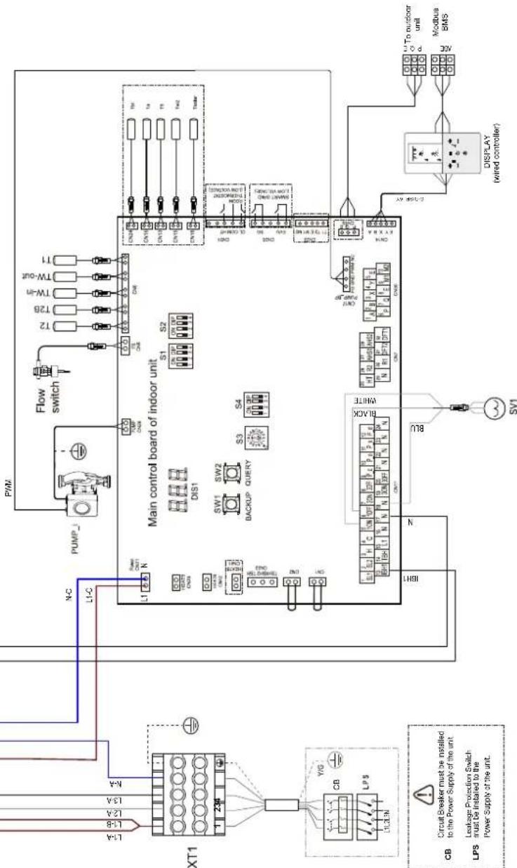
14. DIAGRAMA FRIGORIFICO

LEGENDA
UNIDADE EXTERNA
E1 Compressor
E2 Valvula de quatre vias
E3 Separador gás-liquido
E4 Permutador de calor do lado do ar
E5 Valvula de expansao eletronica
E6 Valvula eletromagnética unidirectional
E7 Filtr0
E8 Sensor de temperatura de descarga
E9 Sensor de temperatura externa
E10 Sonda do permutador externo
E11 Valvula de paragem (gas)
E12 Valvula de paragem (liquido)
E13 Pressostato de alta pressao
E14 Interruptor de baixa pressao
E15 Sensor de pressão
E16 Capilar
E17 Sensor de temperatura de aspiração
UNIDADE INTERNAL
8 Saía do equipoamento
9 Saida de agua para uso domestico
10 Entrada de agua para uso dométrico
11 Entrada do equipamento
14 Valvula de segurarca
36 Valvula automática de expurgo de ar
56 Vaso de expansao
145 Manometro de agua
FL Fluxostato
G Linha do gás
IBH Aquecedor eltrico do equipamento
L Linha do liguido
Pi Circulador de agua
SP Permutador de calor em placas
SV1 Valvula desviadora
T1 Sonda de temperatura da agua de saida da bomba de calor
T2 Sonda de temperatura do refrigerante liquido da bomba de calor
T2B Sonda de temperatura do gás refrigerante da bomba de calor
TW_in Sonda de temperatura da agua de entrada do permutador em placas
TW_out Sonda de temperatura da agua de saida do permutador em placas
15. CERTIFICADO DE GARANTIA
CERTIFICADO DE GARANTIA - FERROLI
A Ferroli garante os equipamentos que fornece de acordo com a leiisao portuguesa D.L. 67/2003 de 8 de Abril, alterado pelo D.L. 84/2008, de 21 de Maio, a chamada Lei das Garantias na vendal de Bens de Consumo.
8.5.3 Réglages ECS (Dhw settings) 310
Anti-légionelle (Disinfect) 310
Charg. Rapide Ecs (Fast Dhw). 310
Reserv. Chauf. (Tank Heater) 310
Pompe ECS (Dhw Pump Circ) 310
8.5.4 Options 310
Mode Silencieux (Silent Mode) 310
Mode Vacances (Holiday) 311
| Unité intérieure | 10 16 | 16T | UM | ||||||||
| Branchement du fluide réfrigérant | 3/8" (1) | 3/8" (1) | 3/8' 3/8' | 3/8' 3/8' 3/8' 3/8' 3/8' | 3/8' 3/8' SAE | ||||||
| Branchement du gaz réfrigérant | 5/8" | 5/8" | 5/8" | 5/8" | 5/8" | 5/8" | 5/8" | 5/8" | 5/8" | 5/8" | SAE |
7.5 Raccordements hydrauliques

ATTENTION
Mode Economy (Eco Mode)
User menu > Preset temp > Eco Mode
8.5.3 Reglages ECS (Dhw settings)
```bash User menu > Dhw settings
Anti-Légionelle (Disinfect)
User menu > Dhw settings > Disinfect
Charg. Rapide Ecs (Fast Dhw)
User menu > Dhw settings > Fast Dhw
Pompe ECS (Dhw Pump Circ)
User menu > Dhw settings > Dhw Pump Circ
Mode Vacances (Holiday)
User menu > Options > Holiday
8.5.5 Service information
User menu > For Serviceman
| COURBES DE CHAUFFE (WTS) MODE RAFRAÎCHISSEMENT | ||||||||||
| T4 (température air extérieur) [°C] | -10 14 | 15 21 22 | 29 30 46 | id Courbe de chauffe | Type d'apparéil sélectionné sur la télécommande | Courbes de chauffe définies | ||||
| T1S ou T2S(tempsérature de consignée eau système) [°C] | 16,0 16,0 11,0 11,0 8,0 8,0 5,0 5,0 1 | Ventilo-convecteur C1 | ||||||||
| 17,0 17,0 12,0 12,0 9,0 9,0 6,0 6,0 2 | ||||||||||
| 18,0 18,0 13,0 13,0 10,0 10,0 7,0 7,0 3 | ||||||||||
| 19,0 19,0 14,0 14,0 11,0 11,0 8,0 8,0 4 | ||||||||||
| 20,0 20,0 15,0 15,0 12,0 12,0 9,0 9,0 5 | ||||||||||
| 21,0 21,0 16,0 16,0 13,0 13,0 10,0 10,0 6 | ||||||||||
| 22,0 22,0 17,0 17,0 14,0 14,0 11,0 11,0 7 | ||||||||||
| 23,0 23,0 18,0 18,0 15,0 15,0 12,0 12,0 8 | ||||||||||
| 20,0 20,0 18,0 18,0 17,0 17,0 16,0 16,0 1 | Chauffage à plan-cher chauffant ou radiateur | C2 | ||||||||
| 21,0 21,0 19,0 19,0 18,0 17,0 17,0 2 | ||||||||||
| 22,0 22,0 20,0 20,0 19,0 19,0 17,0 17,0 3 | ||||||||||
| 23,0 23,0 21,0 21,0 19,0 19,0 18,0 18,0 4 | ||||||||||
| 24,0 24,0 21,0 21,0 20,0 20,0 18,0 18,0 5 | ||||||||||
| 24,0 24,0 22,0 22,0 20,0 20,0 19,0 19,0 6 | ||||||||||
| 25,0 25,0 22,0 22,0 21,0 21,0 19,0 19,0 7 | ||||||||||
| 25,0 25,0 23,0 23,0 21,0 21,0 20,0 20,0 8 | ||||||||||
| Unit type | ||
| Prolie | S | ST |
| Tol | Accessory | Accessory |
| To | Accessory | Accessory |
| TS | Supplied and connected to instaler | Supplied and already connected |
| TW2 | Accessory | Accessory |
| Toler | Accessory | Accessory |
| AHS | Additional heat source |
| DHW | Domestic hot water |
| HTCL | Heat model/Cool mode(harmonicity) |
| KMS-KMT1 | AC Contactor |
| SV1 | Motorized 3-way valve (field supply) |
| SV2 | Motorized 2-way valve (field supply) |
| SV3 | Mining value(solid supply) |
| PUMP2 | Internal circulator pump |
| P_c | Zone 2 pump(feld supply) |
| P_d | DHB pump pump(feld supply) |
| P_e | Outside circulator pump (field supply) or Zone 1 pump (field supply) |
| P_s | Solar pump |
| XTI | Terminal block |
| RT | Room thermostat |
| SG | Solar energy |
| EVU | Commercial power |
| DETAILED OR PROTECTION TABLE | |
| Displn | Fault or Protection |
| S0 | Water flow fault(after 3 times EB) |
| S3 | Communication fault between controller and indoor unit |
| H0 | Communication fault between indoor unit and outdoor unit |
| E3 | Final outlet water temp. sensor(T1) fault |
| E4 | Water tank temp. sensor(T6) fault |
| E8 | Water flow fault |
| G6 | Hot water temp. sensor(Te_in) fault |
| EE | Indoor unit EEErom fault |
| HD | Refrigerant liquid temp. sensor(T2) fault |
| HD | Retropaner gas temp. sensor(T2B) fault |
| HA | Outlet water temp. sensor(Te_out) fault |
| HS | Three times "PP" protection and "Tw_out<7°C" |
| HS | Room temp. sensor(Tai) fault |
| HS | Outlet water for zone 2 temp. sensor (T1b) fault |
| Pb | Anti-heat mode |
| PS | [Te_out - Te_in] value too big protection |
| PP | Te_out - Te_in unusual protection |


14. SCHEMA FRIGORIFIQUE

CONDITIONS DE LA GARANTIE
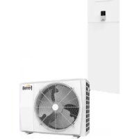
- Caric. Rapido Acs (Fast Dhw)
- Service information
- SCHEMA FRIGORIFERO
- LEGENDA
- UNITÀ ESTERNA
- Allowed uses
- Note
- SUMMARY
- SAFETY PRECAUTIONS
- DANGER
- WARNING
- CAUTION
- Special requirements for R32 refrigerant
- About Fluorinated Gasses
- Information servicing
- 1) Checks to the area
- 2) Work procedure
- 3) General work area
- 4) Checking for presence of refrigerant
- 5) Presence of fire extinguisher.
- 6) No ignition sources
- 7) Ventilated area
- 8) Checks to the refrigerating equipment
- 9) Checks to electrical devices
- 10) Repairs to sealed components
- 11) Repair to intrinsically safe components
- 12) Cabling
- 13) Detection of flammable refrigerants
- 14) Removal and evacuation
- 15) Charging procedures
- 16) Decommissioning
- 17) Labelling
- 18) Recovery
- 20) Transportation, marking and storage for units
- GENERAL FEATURES
- Presentation of the system
- >GENERAL CHARACTERISTICS:
- >INDOOR UNIT FEATURES
- >OUTDOORUNITFEATURES
- >OUTDOOR UNIT ACCESSORIES
- >SYSTEM ACCESSORIES
- Components supplied with the indoor unit
- The control system
- TECHNICAL DATA AN PERFORMANCE
- Available static pressure
- DIMENSIONAL AND PHYSICAL DATA
- GENERAL VIEW AND INTERNAL UNIT HYDRAULIC DIAGRAM
- LEGEND
- SYSTEM EXEMPLARY SCHEMES
- INSTALLATION
- Inspections on arrival
- Packing and storing
- Installation requirements
- Selecting the installation site and minimum operating area for indoor unit
- Limits to the length and heigth difference of refrigerant pipes
- Refrigerant connections
- To the outdoor unit
- Airtight test and leakage detection
- Air purge with vacuum pump
- Heat insulation
- Refrigerant amount to be added
- Hydraulic connections
- Antifreeze plant, antifreeze fluids, additives and inhibitors
- Water filter
- Tips for a successful installation
- Filling with water
- Water circuit anti-freeze protection
- Water piping insulation
- Electrical connections
- Electrical data
- Example of basic connections for a single phase system
- How to access to the electric box
- NB
- Legend:
- User connections
- - Room thermostat method A (mode set control)
- - Room thermostat method B (one zone control)
- - Room thermostat method C (double zone control)
- HT-COM-CL - Room thermostat (Low voltage)
- Photovoltaic input and smart grid operation:
- EVU-SG - Photovoltaic input and smart grid
- USER INTERFACE
- Key function description
- Meaning of display icons
- Switching ON and OFF DHW and plant
- Single function power off / on:
- General shutdown:
- HEAT, COOL and DHW setpoint settings
- Heat / Cool operating mode selection (Operation Mode)
- Daily schedule / climatic curves / Eco mode (Preset Temp)
- Weekly schedule
- Cool mode weekly schedule (Preset Temp. Cool)
- Heat mode weekly schedule (Preset Temp. Heat)
- Climatic curves (Weather Temp Set)
- DHW setting (Dhw settings)
- Antilegionella (Disinfect)
- Fast DHW (Fast Dhw)
- Tank heater (Tank Heater)
- Options
- Silent Mode (Silent Mode)
- Holiday mode (Holiday)
- Plant Backup Heater (Backup Heater)
- Error code (Error code)
- Parameters (Parameters)
- Display
- Operation Parameter (Operation Parameter)
- START-UP AND CONFIGURATION
- Dip switch setting
- Access to Service menu (For Serviceman)
- Climatic curves
- Temperature curves for heating mode and ECO heating mode
- Climatic curve 9 in heating mode settable by the user
- Temperature curves for cooling mode
- Climatic curve 9 in cooling mode settable by the user
- TROUBLESHOOTING
- General guidelines
- General symptoms
- Error codes
- 11.COMMISSIONING
- Heat pump commissioning
- Preliminary heat pump checks
- Refrigerating part
- Disconnect the power supply before carrying out any operation on the electrical panel of the unit.
- Setting to be done during the initial check of the product
- Final check before turning on the unit
- Turn on the unit
- MAINTENANCE
- General notes
- IMPORTANT
- All maintenance work and replacements must be carried out by skilled qualified personnel.
- Before carrying out any operation inside the indoor unit, disconnect the power and close the gas cock upstream. Otherwise there may be a danger of explosion, electric shock, suffocation or poisoning.
- Electrical cabinet
- Residual Risks
- b. Elements of risk
- General Rules for Maintenance
- Access to internal components
- ELECTRICAL WIRING DIAGRAM INDOOR UNIT
- Electrical wiring diagram for indoor unit mod. 10-16 (1ph)
- Electrical wiring diagram for indoor unit mod. 16T (3ph)
- OUTDOOR UNIT
- INDOOR UNIT
- limits operatives
- Modo Economy (Eco Mode)
- Ajustes ACS (Dhw settings)
- Antilegionela (Disinfect)
- ESQUEMA FRIGORIFICIO
- LEYENDA
- UNIDAD EXTERIOR
- Modo Fierias (Holiday)
- DIAGRAMA FRIGORIFICO
- UNIDADE EXTERNA
- UNIDADE INTERNAL
- CERTIFICADO DE GARANTIA
- CERTIFICADO DE GARANTIA - FERROLI
- Raccordements hydrauliques
- ATTENTION
- Mode Economy (Eco Mode)
- Reglages ECS (Dhw settings)
- Anti-Légionelle (Disinfect)
- Charg. Rapide Ecs (Fast Dhw)
- Pompe ECS (Dhw Pump Circ)
- Mode Vacances (Holiday)
- SCHEMA FRIGORIFIQUE
- CONDITIONS DE LA GARANTIE
Brand : FERROLI
Model : Omnia S 3.2
Category : Pump