RCA - Pump FERROLI - Free user manual and instructions
Find the device manual for free RCA FERROLI in PDF.


| Product Type | Circulation Pump |
| Brand | Ferroli |
| Model | RCA |
| Application | Heating and hot water systems |
| Rated Power | 45-100 W |
| Max Flow Rate | 3.5 m³/h |
| Max Head | 6 m |
| Operating Voltage | 230 V / 50 Hz |
| Max Operating Temperature | 95 °C |
| Port Connections | 1" BSP (male) |
| Insulation Class | H |
| Protection Rating | IP44 |
| Dimensions (L x W x H) | 180 x 120 x 130 mm |
| Weight | 2.5 kg |
| Material (Housing) | Cast iron / Stainless steel |
| Impeller Material | Technical polymer |
| Installation Position | Horizontal or vertical |
| Speed Control | 3-speed manual switch |
| Noise Level | < 40 dB(A) |
| Maintenance | Bearings sealed, no maintenance |
| Package Contents | Pump, gaskets, manual |
Frequently Asked Questions - RCA FERROLI
User questions about RCA FERROLI
0 question about this device. Answer the ones you know or ask your own.
Ask a new question about this device
Download the instructions for your Pump in PDF format for free! Find your manual RCA - FERROLI and take your electronic device back in hand. On this page are published all the documents necessary for the use of your device. RCA by FERROLI.
USER MANUAL RCA FERROLI
Cod. 3QE47290 - Rev. 00 - 10/2021
natural_image
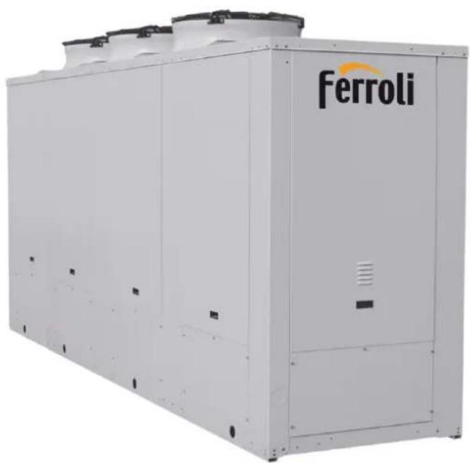
Exterior view of a Ferroli industrial cooling unit (no signage or text beyond brand logo)EN INSTALLATION, MAINTENANCE AND USER MANUAL
GENERAL 4
1.1 DOCUMENT INFORMATION 4
1.2 RANGE 4
1.3 ACCESSORIES 5
1.4 COMPLIANCE 5
1.5 MACHINE IDENTIFICATION 5
1.6 INTENDED USE 5
1.7 GENERAL PRECAUTIONS 5
1.8 BASIC SAFETY RULES 5
1.9 RESIDUAL RISK 6
1.10 USER GUIDELINES 6
1.11 MACHINE DESCRIPTION 7
SHIPMENT 8
2.1 INSPECTION ON RECEIPT 8
2.2 POSITION OF THE EQUIPMENT 8
2.3 EQUIPMENT 8
2.4 STORAGE 8
2.5 HANDLING 8
2.6 UNPACKING 9
2.7 ACCESS TO INTERNAL PARTS 9
5.2 CONNECTIONS OF THE ACCESSORIES 15
COMMISSIONING
6.1 PRELIMINARY INSPECTIONS 16
6.2 FIRST START-UP OR RESTART AFTER LONG INACTIVITY 16
6.3 SHUT-DOWN 16
6.4 FLOW RATE CALIBRATION 17
CONTROL PANEL
7.1 USER INTERFACE 18
7.2 SWITCH ON AND OFF 19
7.3 SETTINGS 19
7.4 UNIT STATUS 21
7.5 PLANNING 23
7.6 ALARMS 24
MAINTENANCE
8.1 MAINTENANCE 28
8.2 WEEKLY CHECKS 28
8.3 MONTHLY CHECKS 28
8.4 ANNUAL CHECKS 28
8.5 WATER CIRCUIT 28
8.6 REFRIGERANT CIRCUIT 29
8.7 DECOMMISSIONING AND DISPOSING 29
28
1. General
1.1 Document information
1.2 Range
1.3 Accessories
1.4 Compliance
1.5 Machine identification
1.6 Intended use
1.7 General precautions
1.8 Basic safety rules
1.9 Residual risk
1.10 User guidelines
1.11 Machine description
1.1 Document information
A Chapter
B Sequence of paragraphs
C Preliminary precautions
D Operations

• The manual is divided into chapters as follows:
- General;
- Shipment;
- Installation;
- Water connections;
- Electrical connections:
- Commissioning;
- Control;
- Maintenance.
• The preliminary precautions must be read before performing any of the following operations.
This document uses the following definitions:
- Danger zones: any area inside and/or near the machine in which the presence of an exposed person constitutes a risk to his/her own health and safety.
- Exposed person: any person who is entirely or partially in a danger zone.
- Operator/Maintenance Technician: the person/s assigned to operate, adjust, service, repair or move the machine.
1.1.1 Symbols
• This publication contains the following symbols:
| Danger | Draws attention to actions that can cause serious injury if not performed correctly. | |
| Prohibited Draws attention to actions that impose a prohibition. | ||
1.2 Range
| RCA 50 | |
| RCA 60 | |
| RCA 65 | |
| RCA 75 | |
| RCA 85 | |
| RCA 100 | |
| RCA 115 | |
| RCA 130 | |
| RCA 155 | |
| RCA 180 |
1.2.1 Available versions
| RCA R AB | Cooling only |
| RCA P AB | Reversible Heat Pump |
| RCA R AX | Super silenced cooling only |
| RCA P AX | Super silenced reversible Heat Pump |
1.3 Accessories
Factory fitted accessories
| IM Automatic circuit breakers | |
| SI Unit silencement | |
| RFM Cooling circuit shut-off valve on discharge line | |
| RFL Cooling circuit shut-off valve on liquid line | |
| CT Condensing control down to 0 °C | |
| CC Condensing control down to -20 °C | |
| BT Low water temperature kit | |
| EC EC Inverter fans | |
| ECH EC Inverter fans with high available static pressure | |
| DS Desuperheater | |
| RT Total heat recovery | |
| TX Coil with pre-coated fins | |
| SI Inertial tank | |
| PS Single circulating pump | |
| PD Double circulating pump | |
| FE Antifreeze heater for evaporator | |
| FA Antifreeze heater for tank | |
| SS Soft start | |
Loose accessories
| MN High and low pressure gauges |
| CR Remote control panel |
| RP Coils protection metallic guards |
| AG Rubber shock absorbers |
| AM Spring shock absorbers |
1.4 Compliance
The device complies with the following standards:
• Machinery Directive 2006/42/CE
• PED Directive 2014/68/EU
• Electromagnetic Compatibility Directive 2014/30/UE
• LVD Directive: 2014/35/UE
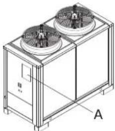
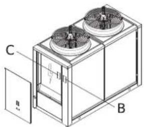
1.5 Machine identification
A Package plate
natural_image
Technical line drawing of a dual-chamber HVAC unit with fans and control panel (no text or symbols)B Frame feature plate
C Electrical board feature plate
natural_image
Technical line drawing of a two-tiered industrial fan or cooling unit with labeled components (no text or symbols present)The equipment can be identified from:
- Packaging plate.
- It shows the identification data of the equipment.
- Frame feature plate.
- Affixed on the machine, it shows the technical and performance data of the equipment.
• Electrical board feature plate.
- Affixed on the panel from which the electrical board is accessed, it shows the electrical data of the equipment.
If it is lost or deteriorated, request a duplicate from Technical Support.

Tampering with, removal and deterioration of the identification plates complicate any installation, maintenance and spare part request.
1.6 Intended use
This unit is designed to cool water (potentially added with inhibited ethylene glycol) that circulates in a closed circuit.
The heat pump units can cool or heat the water circuit, depending on the selected operating cycle.
The heat recovery units can act as a sub-product, heating the water that circulates in a second closed circuit.
The hot or cold air produced by the machine, may be used for air conditioning systems or industrial processes.

Any other use of the machine is forbidden.

Do not use flammable products near the machine.

Do not use substances that can form explosive mixtures close to the machine.

Do not use the machine where there are problems of environmental impact.
1.7 General precautions
- These units must be installed by a qualified company that at the end of the work provides the operator with a declaration of conformity with the regulations in force and the instructions provided by this manufacturer in this document.
• These units must comply with their intended use in line with their performance characteristics. - Wear suitable and accident prevention clothing and equipment during installation and/or maintenance. The manufacturer declines any liability for non-compliance with safety and accident prevention regulations in force.
- All unit installation, connection, start-up and shut-down operations must only be implemented by qualified and authorised personnel.
- Comply with the laws in force in the country where the machine is installed, concerning the use and disposal of the packaging, the products used for cleaning and maintenance and for the management when the unit life cycle is complete.
- Any repairs or maintenance must be performed by the technical support of the manufacturer or by qualified personnel, in accordance with this publication.
- Preferably use original spare parts when replacing components.
- If the refrigerant should leak, ventilate the room. The liquid refrigerant produces toxic gas when exposed to a flame.
- In the case of a malfunction or spill of liquid or gas refrigerant, set the main switch to "off" and close the shut-off valves. Promptly call technical support or professional personnel. Do not intervene personally on the unit.
- If the outside temperature can drop below zero, there is a freezing hazard and the system must be drained or anti-freeze must be added.
- Based on CE Standard no. 842/2006 on certain fluorinated greenhouse gases, it is mandatory to indicate the total amount of refrigerant in the installed system. This information is present in the technical plate found in the outdoor unit.
- This unit contains fluorinated greenhouse gas covered by the Kyoto Protocol. Maintenance and disposal must be carried out only by qualified personnel.
• This unit contains flammable gas. - Read with attention the prescriptions on residual risks indicated in the use and maintenance manual.
1.8 Basic safety rules
Using products that require electricity and water require some basic safety rules to be complied with, such as:
It is prohibited to operate the unit before having disconnecting it from the power supply by setting the main switch to "off".
It is prohibited to modify the safety devices or the settings without authorisation and instructions from the manufacturer of the unit.
It is prohibited to pull, detach or twist the electrical cables coming from the unit, even if it is disconnected from the power supply.
It is strictly prohibited to touch any moving parts, stand between them or introduce pointed objects through the grids.
It is prohibited to use gas and water pipes to earth the unit.
It is prohibited to touch the unit when barefoot or with wet or damp parts of the body.
It is prohibited to stand on the unit, sit down on it and/or lean any type of object against it.
It is prohibited to dispose of and leave the packaging material in the reach of children as it can be a potential source of danger.
It is prohibited for children or unassisted disabled persons to use the unit.
It is prohibited to introduce R410A in the atmosphere: R410A is a fluorinated greenhouse gas referred to in the Kyoto Protocol with a Global Warming Potential (GWP) of 1975.
1.9 Residual risk
Description
The description of the residual risk considers the following elements:
• the type of dangers those working around the machine are subject to;
• a description of main risks;
• who could be exposed to such risks;
• what are the main safety measures adopted to reduce the risk of injury.
The guidelines for the prevention of accidents reported below, with reference to the relative areas of residual risk, must be integrated with all the general instructions of this chapter and with the accident prevention regulations in force in the destination country of the system.
Residual risk near the machine
- Electrocution, if the electrical connection and earthing of the machine are not carried out correctly.
• Cuts or abrasions due to the presence of sharp edges. - Suction of substances in the installation site and subsequent dispersion in the environment.
• Projection of any object that may fall on the fan blades. - Leakage of water (in case of a fault).
- Formation of condensation water and ice in the area in front of the machine during the heating operation of the heat pump machines.
- Micro-climate alteration (during operation).
- Noise emission (during operation). The sound pressure levels of the individual units are listed in the technical booklet.
- Oil leaks (due to a fault).
• Refrigerant gas leak (due to a fault).
Refrigerant gas is a greenhouse gas effect substance. Vapours are heavier than air and they can cause suffocation by reducing oxygen available for breathing. Rapid evaporation of the liquid can cause freezing.
Measures to be adopted if refrigerant gas leaks
- Product type:
-R410A
First aid measures
- General information:
- do not administer anything to an unconscious person.
• Inhalation:
- transfer outdoors.
- use oxygen or artificial respiration if needed.
- do not administer adrenaline or similar drugs.
- Contact with eyes:
- rinse thoroughly with plenty of water for at least 15 minutes and consult a doctor.
- Contact with skin:
- wash immediately with plenty of water
- immediately remove all contaminated clothing
Measures in the event of accidental spillage
- Personal precautions:
- Move all personnel to safe areas.
- Provide adequate ventilation.
- Use personal protective equipment.
• Environmental precautions:
- Intercept the emission.
- Cleaning methods:
- Use absorbent products.
Operations with removed panels
Some of the operations and/or tests described below require the removal of the panels to access inside the unit.
There may be hot surfaces (piping, compressor, etc.) or cold (compressor, intake separator, etc.), sharp edges (coil fins) or moving parts (fans) even with the machine stationary.

The power supply must be disconnected before removing any panel.

Operations that require the panels to be opened must only be carried out by qualified personnel wearing personal protective equipment.
1.10 User guidelines
- Keep this manual together with the wiring diagram in a place that is accessible by the operator.
• Take note of the unit identification data so as to provide them to the service centre when required (see the "Machine identification" paragraph). -
It is recommended to keep track of the operations carried out on the unit, so as to facilitate any troubleshooting.
• In case of a fault or malfunction: -
verify the type of alarm to notify the service centre;
- immediately disable the unit without resetting the alarm;
- contact an authorised service centre;
- request original spare parts.
- Request the installer to be trained on:
- switching on/shut-down;
- shutting down for long periods;
- maintenance;
- what to do/not to do in case of a fault.
1.11 Machine description
1.11.1 Features
Frame.
Self-supporting galvanised steel frame further protected with polyester powder painting.
Easy to remove panels allow access to the inside of the unit for maintenance and repair operations.
Compressors.
Scroll with oil sight glass.
They are fitted with internal overheat protection and crankcase heater, installed on rubber shock absorbers.
Fans.
Axial fans directly coupled to a three-phase electric motor with external rotor.
A safety fan guard is fitted on the air flow outlet.
Fans with low rpm are fitted on super silenced units and therefore some models have more fans.
Condenser.
Made up of two finned coils with copper pipes and aluminium fins. Circuits are made to create two independent circuits.
Circuits are made so as to create two independent circuits.
Evaporator.
Evaporator AISI 316 stainless steel braze welded plates type with two independent circuits on the refrigerant side and one on the water side, complete with water differential pressure switch. On the Heat Pump units it is always installed an antifreeze heater.
Electrical board.
It includes: main switch with door safety interlock; fuses; thermal protection relays for compressors; thermocontacts for fans; interface relays; electrical terminals for external connections.
Microprocessor.
For the automatic control of the unit.
It allows the continuous display of the operational status of the unit, control set and real water temperature and, in case of partial or total block of the unit, indication of security device that intervened.
Chiller versions refrigerant circuit.
Made with copper pipes, it includes for all models the following components: thermostatic expansion valve with external equalisation; filter drier; level and humidity indicator; high and low pressure switches (with fixed setting).
Reversible heat pump versions refrigerant circuit.
The heat pump version, i n a ddition t o t he c components i installed on t he cooling only version, i includes f or e ach c circuit: 4-way r reversing valve; s uction l liquid s separator ; liquid r receiver; check valves.
Versions water circuit.
It includes: evaporator; temperature sensor; antifreeze sensor; water differential pressure switch; manual air vent; water drain.
2. Shipment
2.1 Inspection on receipt
2.2 Position of the equipment
2.3 Equipment
2.4 Storage
2.5 Handling
2.6 Unpacking
2.7 Access to internal parts
2.8 Resting on the ground
2.1 Inspection on receipt
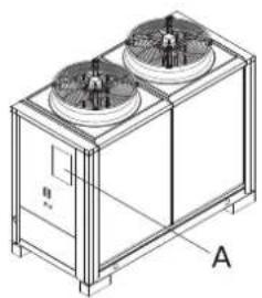
A Packaging plate
natural_image
Technical line drawing of a dual-chamber HVAC unit with fans and cooling fans (no text or symbols)• Before accepting the delivery, check:
- That the unit has not been damaged during transport.
- That the delivered material is as specified on the shipping document when comparing the data with the package plate 'A'.
• In case of damage or faults:
- Immediately take note of the damage on the shipping document and write: "Accepted with reservations for evident loss/damage during transport".
- Submit a complaint by fax and by registered mail with return receipt to the carrier and the supplier.
2.2 Position of the equipment
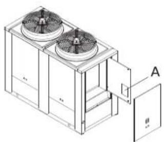
A Pocket for documents
natural_image
Technical line drawing of a dual-chamber HVAC unit with fan and venting (no text or symbols)Keep the documentation in a dry place to prevent deterioration, for at least 10 years for future reference.
Any accessories that are not factory-fitted are supplied in separate packages, with a relevant instruction sheet.
2.3 Equipment
• Installation, operating and maintenance manual;
- Wiring diagram;
• Refrigerant diagram;
• Water diagram;
- List of parameters;
- Declaration of conformity;
- Technical data.
2.4 Storage
The room temperature in which the units are stored must be between -20 / +50°C.
2.5 Handling
• The equipment is designed for two lifting systems according to the length of the machine.
It is prohibited to use the pipes or other components of the machine as lifting points.
2.5.1 Lifting with forks
A Support

natural_image
Technical line drawing of a dual-chamber HVAC unit with fan blades and mounting base (no text or symbols)- Insert the forks from the side to avoid damaging the panels.
- Before placing the machine on the ground remove the wooden supports.
2.5.2 Lifting with a crane
A Bar for lifting (maximum a 63 mm)
B Hole to insert the lifting bar
C Label for holes enabled for lifting

It is recommended to use a system to prevent the belts from slipping from the bars during lifting.
Place spacers and protectors in between prevent damaging the unit.
- Insert the lifting bars into the arranged holes on the base and indicated by the relative labels.
• Lift the unit using suitable belts.
Make sure that all the equipment used for handling (belts, bars, etc.) are appropriate for the weight of the unit.

natural_image
Technical line drawing of a dual-chamber HVAC unit with 30-degree angle标注 (no text or symbols on the diagram itself)During handling it is prohibited to exceed the maximum inclination allowed, as shown in the figure.
2.6 Unpacking
A Wooden support
B Corner protector
C Coil protection

- Remove the wooden supports before resting it definitely on the ground.
- Remove the clear film that wraps the machine.
- Remove the corner protectors.
- Remove the coil protectors.
The machine is supplied without shock absorbers. Install any shock absorbers before resting the machine definitely on the ground.
Only remove the packaging when set in the place of installation.
2.7 Access to internal parts
A Electrical board door
B Electrical board panel
C Side panel
D Rear panel
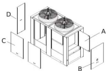
- Unscrew the fixing screws and remove the panels.
To access the electrical board:
- Remove the panels of the electrical board.
- Set the disconnecting switch knob to Off.
- Open the doors of the electrical board.
2.8 Resting on the ground
The unit must be positioned on a perfectly horizontal surface that is able to withstand its weight. Positioning must be performed slowly and so that all support points are touching the floor.
3. Installation
3.1 Installation location requirements
3.2 Work fields
3.3 Unit location
3.4 Verifying clearances (clearance area)
3.1 Installation location requirements
The installation place must be chosen as specified in standard EN 378-1 and the requirements of standard EN 378-3. In any case, the installation site must consider the risks associated with an accidental leak of refrigerant gas contained in the direct expansion units. Do not install the unit near flammable materials or others that could cause a fire. Provide specific fire-fighting measures.
3.2 Work fields
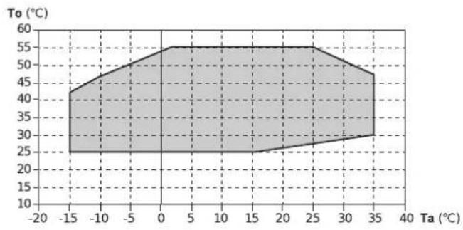
The work fields are indicative, near the operating range limits the units may choke the cooling capacity.
Check the actual capacity by using the capacity tables or the selection software.
Operating mode: heating
area
| Ta (°C) | To (°C) | |---|---| | -15 | 40 | | -10 | 45 | | -5 | 50 | | 0 | 55 | | 5 | 55 | | 10 | 55 | | 15 | 55 | | 20 | 55 | | 25 | 55 | | 30 | 50 | | 35 | 45 | The chart displays a filled area representing the temperature range of Ta (°C) from -20 to 35. The y-axis is labeled 'To (°C)' ranging from 10 to 60. There are no labels for the x-axis or y-axis values. The shaded area represents the area under the curve, which is defined by the label 'To' in the top-left corner. The title 'To (°C)' appears to be a specific variable such as 'Temperature' or 'Temperature at Ta'.Standard operation Ta Room air temperature (°C) To Outlet water temperature (°C)
Operating mode: cooling

area
| Region | Ta (°C) Range | To (°C) Range | |--------|---------------|---------------| | BT | 30–45 | -10 to 15 | | CF | 10–45 | 5 to 15 | | CG | -20 to -15 | 0 to 15 |Ta Room air temperature (°C)
To Outlet water temperature (°C)
Standard operation
CT Operation extension with condensation control up to 0°C
CC Operation extension with condensation control up to -20°C
BT Low water temperature kit
3.3 Unit location

natural_image
Isometric line drawing of a small industrial or laboratory device with a circular top and internal components, enclosed in a transparent box (no text or symbols)The unit should be positioned far from any obstacle.
It is prohibited to place the unit under a roof, canopy or any covering in general.
The heat pump units allow ice and condensation to form that pours on to the floor in front of the unit. Collect and drain the condensation and defrost water to prevent the floor from becoming slippery.

natural_image
Isometric line drawing of a two-tiered industrial or cooling unit with circular indicators, no text or symbols present.It is prohibited to place the unit inside basement windows.
3.3.1 Noise

natural_image
Isometric illustration of a smart air conditioner unit with multiple sensors and signal waves (no text or symbols)During operation, the unit generates noise.

Avoid installation in reverberant environments.

Avoid placing the machine with the side of the coil in the direction where the noise level is more critical.
3.3.2 Windy areas (Resting on the ground)

The wind may alter the operating conditions. Place the unit with the long side parallel to the prevailing wind direction in order to minimise the effects.

Avoid placing it with the coil perpendicular to the direction of the main wind.
3.3.3 Resting on the ground
A Rigid rubber band
H Slab of 10-15 cm

natural_image
Isometric technical diagram of a dual-chamber HVAC unit mounted on a base plate, with dimension labels H and A (no text or symbols beyond labels)- Place the unit on a perfectly level support surface.
- Place a rigid rubber band between the base of the machine and the support surface.

Verify that the support surface withstands the weight of the unit.

Provide a supporting slab of proportional dimensions with the unit if resting on unstable ground.

The slab must be horizontal and able to withstand approximately 200% of the operating weight of the machine.

If necessary, use shock absorbers (rubber or spring).

A drain for the water produced by coils defrosting must be implemented for the heat pump units.
3.4 Verifying clearances (clearance area)
| L1 1800 | |
| L2 1800 | |
| W1 1000 | |
| W2 500 |
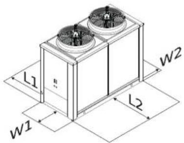
• Installation, in addition to the indicated spaces, must enable access to the authorised personnel for maintenance operations and must take into account the safety distances from any other equipment installed near the machine.
4. Water connections
4.1 Connection diagram
4.2 Position of connections
4.3 Hydraulic data
4.4 Connection to the system
4.5 System fill-up
4.6 Desuperheater connection
4.1 Connection diagram
| 1 Unit | |
| ANT Anti-vibration joint (recommended) | |
| CV Check valve | |
| FL Flow switch (mandatory) | |
| FTR Mesh filter (mandatory) | |
| MN Water gauge | |
| MP Circulating pump | |
| RI Shut-off ball valve | |
| RIC Automatic water filling valve | |
| SFA Automatic air vent (mandatory) | |
| ST Inertial tank | |
| VE Expansion vessel | |
| VSI Safety valve (mandatory) | |
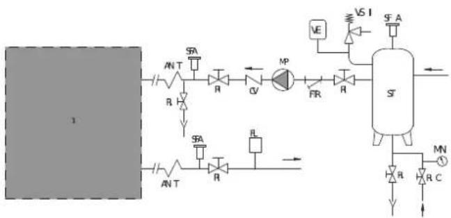
flowchart
graph TD
    A["1"] --> B["AN T"]
    B --> C["SA"]
    C --> D["R"]
    D --> E["GV"]
    E --> F["MP"]
    F --> G["FR"]
    G --> H["R"]
    H --> I["S"]
    I --> J["VS I"]
    J --> K["VA"]
    K --> L["ST"]
    L --> M["MN"]
    M --> N["R"]
    N --> O["R C"]
    O --> P["->"]
    style A fill:#ccc,stroke:#333
    style L fill:#ccc,stroke:#333
Some of the components in the diagram may already be included in the unit with the hydronic kit. Those not included must be provided by the installer.
Connection pipes must have a suitable diameter and be supported so as not to impose their weight on the unit.
4.2 Position of connections
The position of the water connections and the inlet and outlet direction is indicated by the labels on the connections.
4.3 Hydraulic data
4.3.1 Water volume
The machine electronic control, to protect the electrical motor, limits hourly start up of the compressor.
This operation creates oscillations of the water temperature in the draw-off point, affecting plant efficiency.
For a correct operation, the water volume must comply with the following formula:
For cooling only version only
$$ M > 9, 4 5 \times k \times n / N \times (Q f - q) $$
For heat pump version only
$$ M > 9, 4 5 \times k \times n / N \times (Q t - q) + 2, 3 7 \times (Q t - q) $$
M = Minimum water content (l);
k = Factor that takes into account the different water temperature value between the inlet and outlet of the evaporator or condenser;
n = Partition coefficient (n=1 unit up to 4 compressors; n=2 units with more than 4 compressors);
N = N. compressors;
Qf = Cooling capacity (kW);
Qt = Heating capacity (kW);
q = Permanent thermal load in the system (kW), (q=0 if the value is unknown).
| T( K) | K |
| 3 | 1 |
| 4 | 1 |
| 5 | 1 |
| 6 | 1.05 |
| 7 | 1.1 |
| 8 | 1.15 |
| 9 | 1.2 |
| 10 | 1.25 |
For the process application a 50% higher water content is recommended to stabilize the outlet temperature (1.5 x M calculated with the previous formulas).
If the water volume in the circuit (V) does not reach what is indicated, installing a new inertial storage tanks shall be required.
Storage size shall be calculated so that with its volume, added to the water quantity inside the circuit, the value indicated in the formula is reached.
4.3.2 Water features
Water features are important for the proper operation of the machine and for its lifetime.
Extreme water hardness leads to the formation of limestone in exchangers reducing their performance.
The table shows some water parameters to be observed for proper operation of the machine.
| Content | Concentration mg/l or ppm | Material | |
| AISI 316L | Copper | ||
| Content Concentration mg/l or ppm Material | ||||
| pH | <622 | |||
| 6-7.522 | ||||
| 7.5-911 | ||||
| >912 | ||||
| Alkalinity HCO3 | -<7012 | |||
| 70-30011 | ||||
| >30012 | ||||
| Sulphate SO42- | <7011 | |||
| 70-30013 | ||||
| >30013 | ||||
| Alkalinity/Sulphate HCO3-/SO42- | >111 | |||
| <113 | ||||
| Electrical conductivity μS/cm | <1012 | |||
| 10-50011 | ||||
| >50012 | ||||
| Ammonium NH4 | <211 | |||
| 2-2012 | ||||
| >2013 | ||||
| Free chlorine Cl2 | <111 | |||
| 1-531 | ||||
| >533 | ||||
| Hydrogen Sulphide H2S | <0.0511 | |||
| >0.0513 | ||||
| Free Carbon Dioxide | CO2 | <511 | ||
| 5-2012 | ||||
| >2013 | ||||
| Nitrate | NO3 | <10011 | ||
| >10012 | ||||
| Iron | Fe | <0.211 | ||
| >0.212 | ||||
| Aluminium | AL | <0.211 | ||
| >0.212 | ||||
| Manganese | MW | <0.111 | ||
| >0.112 | ||||
1 - Good corrosion resistance.
2 - If different factors of this type are present, corrosion can occur.
3 - Use not recommended.
4.3.3 Protection against freezing
If you do not wish to drain the system during periods where the machine is not used, the water may freeze, or if the system must operate with temperatures less than 5^ C, ethylene glycol must be mixed with the water.
Adding glycol changes the physical characteristics of the water and the performance of the machine.
The table indicates the multiplicative factors to calculate the performance change based on the percentage of glycol used.
| % G 10 20 30 40 | 50 | ||||
| Tc | -4.5 | -9.5 -15.5 | -21.5 | -32.5 | |
| CQ | 0.975 | 0.953 | 0.931 | 0.914 | 0.882 |
| CP | 0.998 | 0.995 | 0.99 | 0.985 | 0.975 |
| CG | 1.01 | 1.04 | 1.08 | 1.14 | 1.2 |
| CP | 1.05 | 1.13 | 1.21 | 1.26 | 1.32 |
% G = Glycol percentage
Tc = Water freezing temperature (°C)
CQ = Cooling capacity correction factor
CP = Electrical power absorbed correction factor
CG = Water flow correction factor
Cp = Pressure drops correction factor
4.4 Connection to the system
4.4.1 Models without hydronic kit
A Rear panel

natural_image
Isometric line drawing of a multi-compartment industrial or cooling unit with fans and doors, labeled A (no text or symbols on the diagram itself)In these models, the connections are positioned inside the unit.
- Remove the inspection panels.
- Remove the protection caps from the connections.
- Connect the pipes to the connections.
natural_image
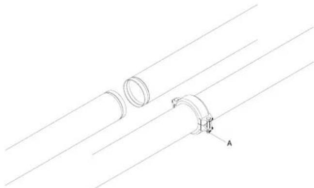
Technical line drawing of two pipe fittings with a clamp, showing alignment lines (no text or symbols)For threaded connections:
- Fasten by holding a part in order to tighten the other part.
• It is recommended to seal with hemp and green paste.
For Victaulic connections:
- Secure by using the appropriate coupling system (not supplied).

Provide shut-off valves and anti-vibration joints on the connection pipes.

During the hydraulic connection operations, never operate with free flames near or inside the unit.
4.4.2 Models with hydronic kit

natural_image
Isometric line drawing of a multi-compartment industrial fan unit with cooling fans and a coiled spring (no text or symbols)In these models, the connections are positioned outside the unit.
- Remove the protection caps from the connections.
- Connect the pipes to the connections.
For threaded connections:
- Fasten by holding a part in order to tighten the other part.
• It is recommended to seal with hemp and green paste.
For Victaulic connections:
- Secure by using the appropriate coupling system (not supplied).
4.5 System fill-up
A Pump drainage shut-off valve

natural_image
Technical line drawing of a motor pump assembly with labeled component A (no text or symbols beyond label)- Before performing any operation, make sure the main switch is off.
- If the hydronic kit is installed, make sure the pump drainage shut-off valve (A) is closed.
• Make sure that the drain valves are closed and the air vent valves are open.
- Open the shut-off valves of the water system.
- Start filling.
- When the water begins to leak from the vent valves, close them and bring the water pressure to the value required by the system (1 - 1.5 bar). Keep in mind that safety valve calibration is 6 bar.
- When the water pressure has stabilised (read the pressure gauges installed on the upper side), close the fill-up valve and check the tightness of the various joints.
It is advisable to periodically check the pressure in the water circuits to prevent malfunctions.
The water circuits must always be topped-up with the pumps off.
4.6 Desuperheater connection
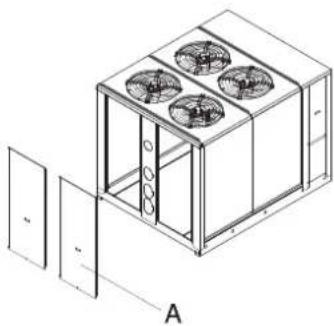
A Rear panel
natural_image
Isometric line drawing of a multi-compartment industrial or cooling unit with fans and doors, labeled A (no text or symbols on the diagram itself)The connections are positioned inside the unit.
- Remove the inspection panels (A).
- Remove the protection caps from the connections.
- Connect the pipes to the connections.
For threaded connections:
- Fasten by holding a part in order to tighten the other part.
• It is recommended to seal with hemp and green paste.
For Victaulic connections:
- Secure by using the appropriate coupling system (not supplied).
5. Electrical connections
5.1 Machine connection
5.2 Connections of the accessories
5.1 Machine connection
A Pre-cut for front inlet
B Hole for bottom inlet

natural_image
Isometric line drawing of a two-tiered cabinet or enclosure with labeled points A and B (no text or symbols beyond labels)The unit is provided with holes for the power cables inlet. There is a pre-cut hole on the structure and a hole on the base for any input from below.
- Remove the pre-cut.
- Insert the cables from the outside, guiding them towards the electrical board.
Avoid direct contact with non-insulated copper pipes and with the compressor.
It is forbidden to enter the device with electrical cables in positions not specifically required in this booklet.
To set up the electrical connections:
- Unscrew the fixing screws.
- Remove the external panels.
- Set the main switch to 0.
- Turn the two fixing screws 1/4 of a turn and open the board doors.
- Use the hole for the main power cable and the hole for the cables of other external connections.
- Make the connections as shown in the wiring diagram.
- Once the electrical connections are completed, secure the cables by using the cable glands, close the doors of the electrical panel and reassemble the external panels by screwing the fixing screws.
Before connecting the remote ON-OFF switch, remove the jumper from the relative clamps.
5.2 Connections of the accessories
5.2.1 Flow switch
The chiller must only operate in the presence of water flow. The flow switch (if not already present) must be connected as shown in the wiring diagram.
5.2.2 Circulating pump
The circulating pump must always be connected to the control unit as indicated in the wiring diagram. The pump must be started before the chiller is started and stopped after the chiller is stopped (recommended minimum delay: 60 seconds).
5.2.3 External consents
If you wish to enable or disable the unit remotely, connect the external consent to the contacts listed in the wiring diagram.
Avoid placing the control cables in the same duct as the power cables. Always use a suitable shielded cable.
The connection cables must have a minimum cross section of 1.5 mm ^4 .
5.2.4 Connections of the accessories
5.2.4.1 Circulating pump
The circulating pump must always be connected to the control unit as indicated in the wiring diagram. The pump must be started before the chiller is started and stopped after the chiller is stopped (recommended minimum delay: 60 seconds).
6. Commissioning
6.1 Preliminary inspections
6.2 First start-up or restart after long inactivity
6.3 Shut-down
6.4 Flow rate calibration
6.1 Preliminary inspections
6.1.1 Electrical
- Verify that the voltage on terminals L1, L2 and L3 is that shown on the plate of the unit (tolerance allowed) ±5%, which can be checked with a tester. If voltage changes occur frequently, please contact our technical department to choose suitable protections.
- Verify the complete tightness of the fuse holder caps.
- Verify that the crankcase heaters (if applicable) are powered correctly: to check whether the heaters are working properly, check that the bottom of the compressor is at a temperature of 10 to 15 °C higher than the ambient temperature.
- Power and check the correct direction of rotation for the three-phase version, which should be clockwise looking at the motor from the fan side. Otherwise, invert any two of the phase conductors.
6.1.2 Hydraulic
- Make sure that the water circuit has been previously cleaned: it is recommended to wash the water circuit via by-passing the unit and then check the cleanliness of the system filter.
• The machines are shipped with open vents and drains, which must be closed during installation when filling the water circuit. Labels indicate their positions. - In models with a hydronic kit, the water drain cap of the pump has been removed, in order to drain the water contained in it and to avoid freezing problems during the winter season. The cap is inside the envelope containing all documents of the unit.
- Make sure that the hydraulic system has been bled, thereby eliminating any residual air. The operation must be performed by loading gradually and opening the venting devices set up by the installer in the upper part of the system.
- If you are using glycol water you can move the antifreeze set-point. The value must be equal to the value of the freezing temperature of the fluid plus 6K.
6.1.3 Cooling
- Make sure that the pressure gauges (when present) indicate an adequate pressure. Pressure gauges can be fitted with shut-off valves. They should only be opened when necessary and once readings are taken, they must be closed again.
- Check that there is no refrigerant leak, possibly using a leak detector.
6.2 First start-up or restart after long inactivity
6.2.1 Start-up
Activate the machine according to that described in the relative command section.
6.2.1.1 Checks during operation
- Check that the machine does not generate abnormal noise or excessive vibrations.
• After a few hours of operation verify that the crown of the liquid and humidity indicator indicates a dry circuit. - Verify that the machine operates within the optimum working range.
- Verify that there is no excessive presence of bubbles in the liquid indicator. If there are this indicates low refrigerant.
- A few minutes after the compressors are started, during the summer mode cycle, make sure that the condensing temperature is 18 ± 4K higher than the air temperature entering the condenser and that the average evaporating temperature is approximately 5K lower than the water temperature leaving the utility exchanger.
- Verify that the overheating temperature of the refrigerant is between 5 and 7K. To verify:
-
Measure the temperature with a contact thermometer placed on the intake pipe of the condenser.
-
Read the temperature indicated on the pressure gauge connected to the inlet.
- The difference between these temperatures provides the overheating value.
- Verify that the subcooling temperature of the refrigerant is between 4 and 8K. To verify:
- Measure the temperature with a contact thermometer placed on the outlet pipe from the condenser.
- Read the temperature indicated on a pressure gauge connected to the liquid outlet of the condenser.
- The difference between these temperatures provides the subcooling value.
The tests referred to above can be performed using the pressure gauges supplied with the unit (accessories). Once the checks are complete, close the shut-off valves of the pressure gauges.
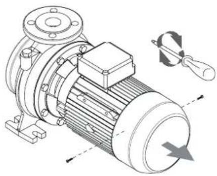
6.2.2 Pump release procedure
natural_image
Technical illustration of an electric motor with internal components and a tool, showing no text or symbols.• Before starting the pump, check that the moving parts rotate freely.
To release the pump:
- Remove the fan cover from the seat of the rear motor cover.
- Use a screwdriver on the present slot on the motor shaft from the fan side.
• In case of blockage, turn the screwdriver by tapping it lightly with a hammer.
- When the operations are completed, reassemble the components in reverse order.
6.3 Shut-down
6.3.1 Temporary shut-down
Disable the machine according to that described in the relative command section.
Do not disconnect the power supply by acting on the disconnecting switch on board the machine or the main switch of the system. If no voltage is present, the crankcase heaters and any anti-freeze healers cannot work, thereby, posing a risk of freezing.
6.3.2 Shut-down for long periods
Not using the unit for a long period of time requires the following operations to be performed:
- Disable the unit in any mode of operation it may be, from the control panel.
- Set the remote switch to "OFF" (if present) after having turned off the unit.
- Disable the internal terminal units by setting the switch of each unit to "off".
- Set the main switch of the system to "off".
- Close the water valves.
If, during the period of inactivity the temperature drops below zero, the system must be fully empties or topped up with antifreeze liquid.
6.4 Flow rate calibration
Once the pump has started, verify that the fluid flow rate of the utilities is within the expected values for the unit.
To verify:
- Use pressure gauges set before and after the circulating pump to measure the pressure difference.
- Verify that the pressure difference measured is equal to the pressure drop in the system, including the heat exchanger.
To correct: - Turn the valve installed downstream of the pump to increase or decrease the pressure difference.
- Mark the position of each valve to reposition it in the same position after closing for maintenance operations.
If there are no pressure gauges: - Verify the temperature difference between the utility fluid input and output when the unit is operating regularly (all compressors on).
- The difference in water temperature between input and output must be between 4^ and 6^ :
- If it is below 4^ C, the water flow rate is too high: slightly close the discharge valve of the pump.
- If it is more than 6^ C, verify the pressure drops in the water circuit.
For units equipped with two pumps, you will have to repeat the calibration for each pump.
7. Control Panel
7.1 User interface
7.2 Switch on and off
7.3 Settings
7.4 Unit Status
7.5 Planning
7.6 Alarms
7.1 User interface
7.1.1 Control panel

The control panel enables all machine functions to be performed, to display its operation and any alarms which may be triggered.
7.1.2 Display

From the control panel display is possible to see the quantities of set values and, via icons, the machine operation.

From the main screen it is possible to visualize the time and the water temperature.

From these icons it is possible to see if the machine is in stand-by and if it is operating in cooling or heating mode.
Operation icons shall be steady or flashing.
Steady: if the order was defined from the digital inlet.
Flashing: if the order was defined from the keys of the control panel.

From these icons it is possible to see if the alarm is intervened in the operation of the machine, if it is operating in energy save mode or if an operating frame was set.

Through the start-up of the arrow keys in correspondence of LEDs on the control panel, it is possible to see how many compressors are working, if the primary exchanger heaters, the exchanger fan and the circulating pump are active. In the upper part of the panel, the arrow keys indicate the active manual defrosting or if there are operations in progress in the programming menu.
7.1.3 Function keys
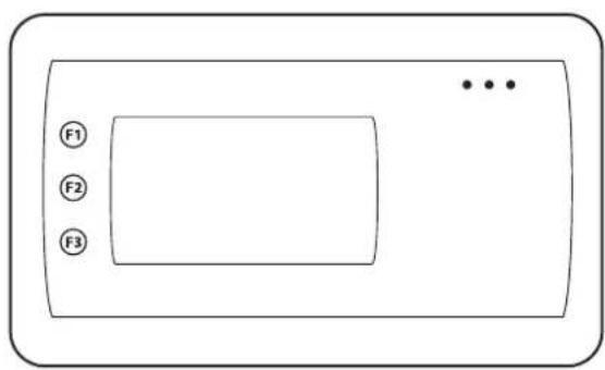
On the control panel there are three function keys:
F1: with press and hold key you can activate the manual defrosting (if there are the activation conditions: heat pump operation and sufficient pressure).
F2: with press and hold key you can change the operation mode.
F3: with press and hold key you can turn the machine on and off.

With the SET key you can enter the status menu or set an set value.
With the ESC key you can return to the previous menu or exit from the selection menu.

natural_image
Simple line drawing of a rectangular device with a central screen and three dots, labeled 'Prg' in the center (no text or symbols on the device itself)With the PRG key you can enter in the selection menu.

natural_image
Simple line drawing of a microwave oven with two side buttons and three dots on the top (no text or symbols)With the UP key you can move around in the menu to increase the values you wish to modify. With press and hold key you can activate the manual defrosting.
With the DOWN key you can move around in the menu to decrease the values you wish to modify.
With press and hold key you can turn the machine on and off.
7.2 Switch on and off
From control panel you can turn the machine on and off.

With press and hold F3 key or DOWN key you can switch from ON state to OFF state and vice versa.

7.3 Settings
7.3.1 Date and time
The control panel features a clock and calendar which allows the management of the alarm history and the planning of operating ranges.
Date and time setting on the control board

Press the SET key to access to the setting menu.

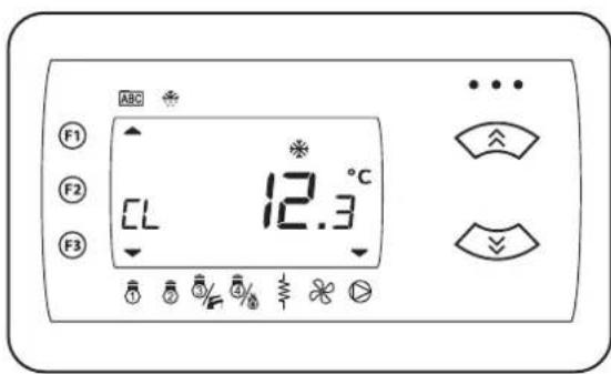
Use UP and DOWN keys to scroll the menu until CL label.
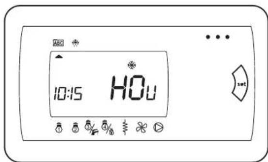
Press the SET key to access to the menu.

With press and hold SET key you can enter in the parameter to modify.
The value will start to flash on the display.
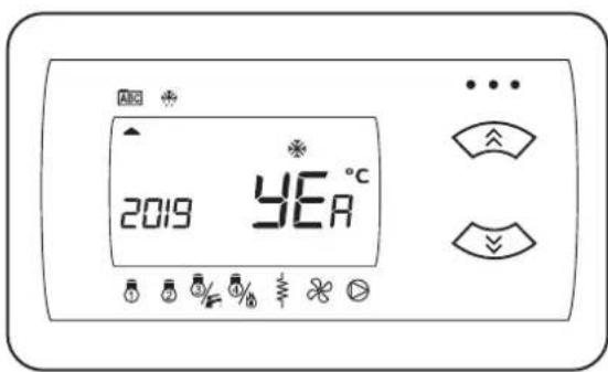
Use UP and DOWN keys to select the value to modify among date, year and time.
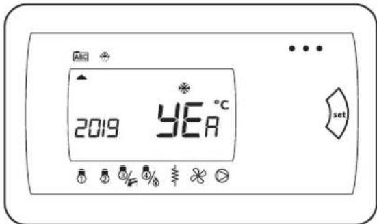
Once chose to value to modify, press again the SET key.

Use UP and DOWN keys to modify the value and press the SET key to save the value set. Repeat the operation to modify date/year and hour parameters.
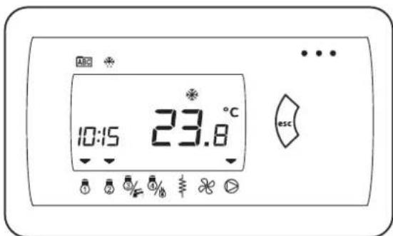
Press the ESC key to come back to the main menu and to exit from setting menu. The control panel will display the main screen.
7.3.2 Operating mode change
The machine operating mode can be changed from the control panel. The selectable modes are: Stand-by (Stby), heating (HEAT) and cooling (COOL).
With press and hold ESC or F2 key you can change the operation mode of the unit, ESC and F2 keys are enabled by the Ui21=1 parameter and by disabling the digital inputs Summer/Winter and ON/Standby.

The display shows the machine operation mode.

Use UP and DOWN keys to modify the operation mode.

Select the desired operation mode.
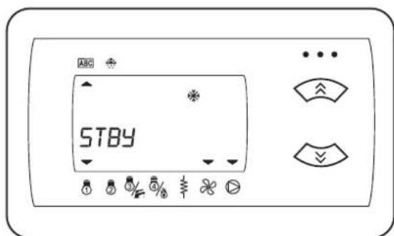
Select the desired operation mode and press the SET key to confirm.
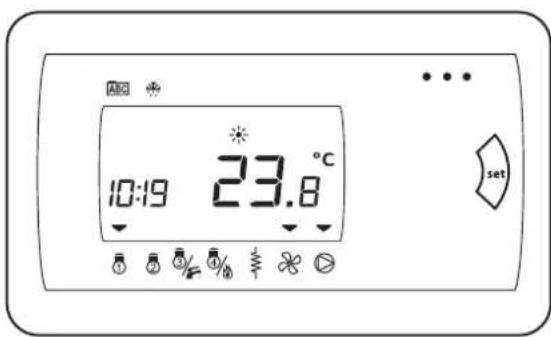
The control panel will display the main screen.
7.3.3 Set-point
The machine inlet water temperature can be set from the control panel.
Press the SET key to access to the menu.
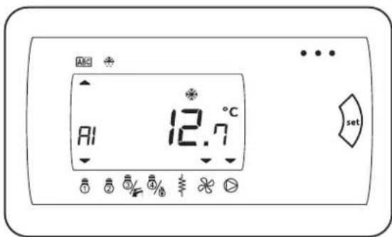
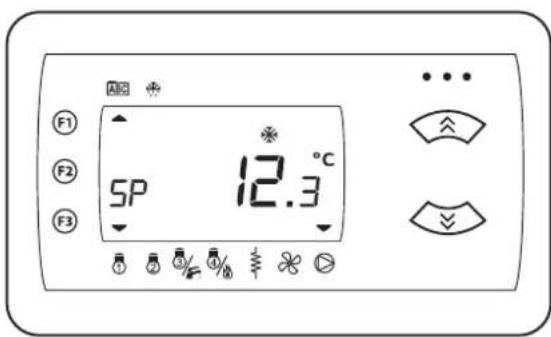
By using UP and DOWN keys select SP label.

Press the SET key to access to Set-point menu.
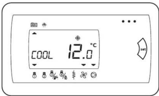
By using UP and DOWN keys it is possible to select the Set-point to modify.
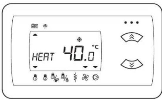
Once selected the set-point to modify, press the SET key.
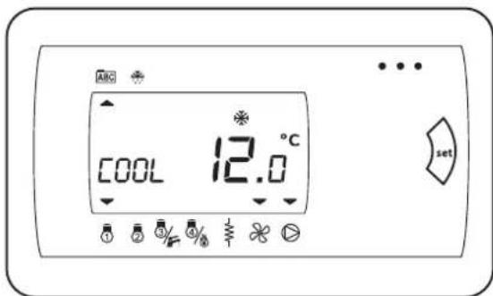
By using UP and DOWN keys it is possible to select the desired value.
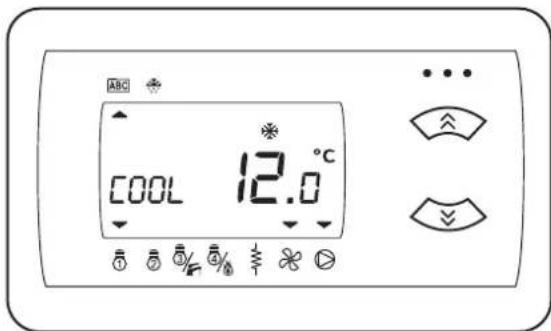
Press the SET key to confirm the set value.

7.4 Unit Status
From control panel it is possible to visualise the status of the machine.
To access to STATUS menu press the SET key.
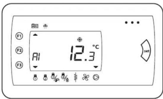
On the display Al label (analogue inlets) appears.
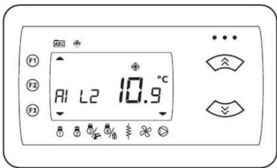
In each label it is possible to press the SET key to enter in the parameters.

In each label it is possible to scroll all parameters by using UP and DOWN keys.
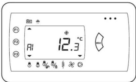
Press the ESC key to return to the main menu.
By using UP and DOWN keys it is possible to visualize different status and values of the machine.
AO (analogue outlets).

DI (digital inlets).

DO (digital outlets).

CL (clock).
SP (selected Set-point).
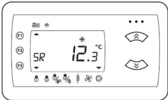
SR (real Set-point).
REL (firmware review).

HR (tens of compressors and pumps working hours).

Press the ESC key to return to the main screen.

7.5 Planning
From control panel it is possible to access to planning menu by pressing the PRG key.

The parameters menu contains the list of editable parameters of the machine.
Press the SET key to access to menu, press the ESC key to exit.
Using UP and DOWN keys it is possible to select the following menu.

The functions menu allows to execute some manual actions on the machine.
Press the SET key to access to menu, press the ESC key to exit.
Using UP and DOWN keys it is possible to select the following menu.

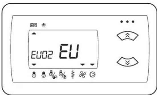
The EU menu allows the visualize all events intervened on the machine: alarm codes, intervention time, reset time and reset type.
Press the SET key to access to menu, press the ESC key to exit.
Using UP and DOWN keys it is possible to select the following menu.

The password menu allows the entrance to the protected area of the control panel.
Press SET to enter the password.

Using UP and DOWN keys it is possible to insert the password.

Press the SET key to confirm the password inserted.

The control panel will visualise the previous screen and the password-protected parameters will be visible and editable.
7.6 Alarms
7.6.1 Alarm presence
In case of poorly functioning of the machine, the ALARM signal and the intervened alarm code appear on the display.

7.6.2 Alarms reset

During the unit operation two types of alarm can intervene: with automatic reset or with manual reset.
In presence of an alarm with automatic reset, the return to regular operation conditions will be automatic at the stop of the causes of its intervention.
The alarm signal and the intervened alarm code will disappear from the display.
In presence of an alarm with manual reset, the return to regular operation conditions occurs through pressing simultaneously UP and DOWN keys and only if the stop of the causes of its intervention.

The alarm signal and the intervened alarm code will disappear from the display.
7.6.3 Alarms history
From control panel it is possible to visualise the history of intervened alarms during the machine operation.
Press the PRG key to return to the main screen.
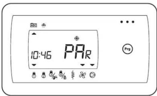
Use UP and DOWN keys to select the EU menu.
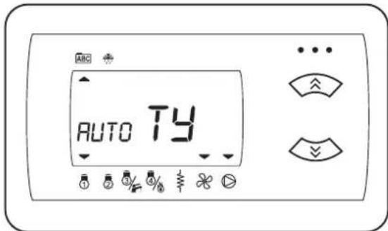
TY: indicates if the intervened alarm is with manual or automatic reset.

Press the SET key to enter the menu containing the list of intervened alarms.
DO: indicates the date when it was rearmed or if the alarm is still active (---).

Use UP and DOWN keys to select the alarm of whom you wish to visualize all information.

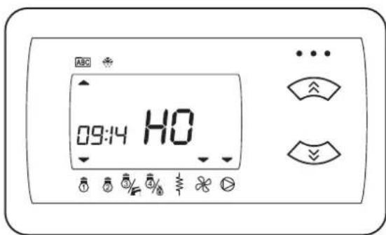
HO: indicates the time when it was rearmed or if the alarm is still active (---).
Once selected the alarm, press the SET key to enter in the information list.
DI: indicates the date when the alarm intervened.
Use UP and DOWN keys to scroll all information about the selected alarm.
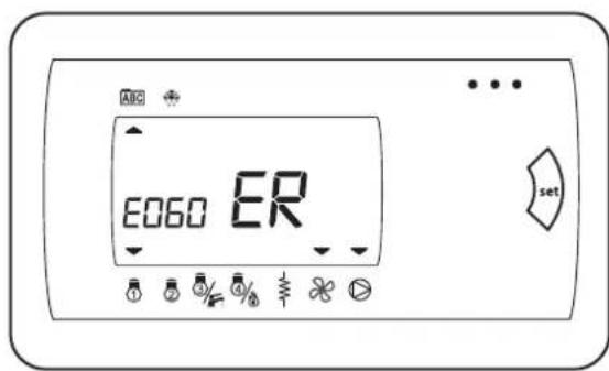
ER: indicates the code of intervened alarm.

HI: indicates the time when an alarm intervened.
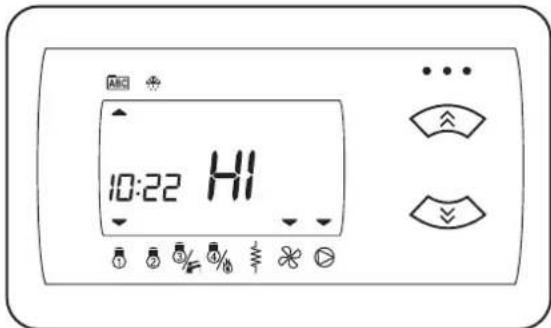
Press the ESC key to come back to the previous menu or to come back to the main screen.
7.6.4 Alarm charts
From alarm charts it is possible to identify the anomaly on the unit.
| Alarm code | Alarm name |
| E000 General alarm | |
| E001 High pressure (digital) circuit 1 | |
| E002 High pressure (digital) circuit 2 | |
| E003 High pressure (analogue) circuit 1 | |
| E004 High pressure (analogue) circuit 2 | |
| E005 Low pressure (digital) | |
| E007 Low pressure (analogue) circuit 1 | |
| E008 Low pressure (analogue) circuit 2 | |
| E009 Unloaded machine | |
| E010 Thermal overload protection compressor 1 | |
| E011 Thermal overload protection compressor 2 | |
| E012 Thermal overload protection compressor 3 | |
| E013 Thermal overload protection compressor 4 | |
| E015 Oil switch compressor 1 | |
| E016 Oil switch compressor 2 | |
| E017 Oil switch compressor 3 | |
| E018 Oil switch compressor 4 | |
| E020 Primary circuit flow switch | |
| E021 Thermal protection pump 1 primary circuit | |
| E022 Thermal protection pump 2 primary circuit | |
| E025 Open circuit flow switch | |
| E026 Open circuit pump thermal protection | |
| E030 Primary circuit antifreeze | |
| E031 Open circuit antifreeze | |
| E032 Vacuum circuit 1 | |
| E033 Vacuum circuit 2 | |
| E035 High temperature | |
| E040 Fans thermal overload protection of the primary exchanger | |
| E041 | Fans thermal overload protection of the disposable exchange of circuit 1 |
| E042 | Fans thermal overload protection of the disposable exchange of circuit 2 |
| E045 Faulty clock error | |
| E046 Clock needs adjusting error | |
| E047 LAN communication error | |
| E048 Anti-legionella | |
| E050 Thermal protection electrical heaters 1 primary exchanger | |
| E051 Thermal protection electrical heaters 2 primary exchanger | |
| E056 Auxiliary outlet thermal protection | |
| E060 | Broken water or air temperature sensor at the primary exchanger inlet |
| E061 | Broken water or air temperature sensor at the primary exchanger outlet of 1 and/or 2 circuit |
| E062 | Broken temperature sensor of the non-returnable exchanger of 1 and/or 2 circuit |
| E063 Faulty open exchanger inlet water temperature sensor | |
| E064 Faulty open exchanger outlet water temperature sensor | |
| E065 Faulty indoor room temperature sensor | |
| E066 Faulty DHW temperature sensor | |
| E067 Faulty display sensor (temperature and/or pressure) | |
| E068 Faulty external temperature sensor | |
| E069 | Broken circuit 1 high pressure inlet, and/or broken circuit 2 high pressure inlet |
| E070 | Broken circuit 1 low pressure inlet, and/or broken circuit 2 low pressure inlet |
| E071 Faulty discharge temperature sensor compressor 1 | |
| E073 Broken dynamic set-point inlet | |
| E074 | Broken primary exchanger pressure of circuit 1, and/or broken primary exchanger pressure of circuit 2 |
| E075 | Broken disposable exchanger pressure of circuit 1, and/or broken disposable exchanger pressure of circuit 3 |
| E080 Configuration Error | |
| E081 Reporting of compressors exceeding hour operation (*) | |
| E085 | Reporting of exceeding hour operation of the primary circuit pump (*) |
| E086 | Reporting of exceeding hour operation of the disposable circuit pump (*) |
| E090 Reporting of registrations exceedance | |
| Alarm code | Alarm name |
| E000 General alarm | |
| E001 High pressure (digital) circuit 1 | |
| E002 High pressure (digital) circuit 2 | |
| E003 High pressure (analogue) circuit 1 | |
| E004 High pressure (analogue) circuit 2 | |
| E005 Low pressure (digital) | |
| E007 Low pressure (analogue) circuit 1 | |
| E008 Low pressure (analogue) circuit 2 | |
| E009 Unloaded machine | |
| E010 Thermal overload protection compressor 1 | |
| E011 Thermal overload protection compressor 2 | |
| E012 Thermal overload protection compressor 3 | |
| E013 Thermal overload protection compressor 4 | |
| E015 Oil switch compressor 1 | |
| E016 Oil switch compressor 2 | |
| E017 Oil switch compressor 3 | |
| E018 Oil switch compressor 4 | |
| E020 Primary circuit flow switch | |
| E021 Thermal protection pump 1 primary circuit | |
| E022 Thermal protection pump 2 primary circuit | |
| E025 Open circuit flow switch | |
| E026 Open circuit pump thermal protection | |
| E030 Primary circuit antifreeze | |
| E031 Open circuit antifreeze | |
| E032 Vacuum circuit 1 | |
| E033 Vacuum circuit 2 | |
| E035 High temperature | |
| E040 Fans thermal overload protection of the primary exchanger | |
| E041 | Fans thermal overload protection of the disposable exchange of circuit 1 |
| E042 | Fans thermal overload protection of the disposable exchange of circuit 2 |
| E045 Faulty clock error | |
| E046 Clock needs adjusting error | |
| E047 LAN communication error | |
| E048 Anti-legionella | |
| E050 Thermal protection electrical heaters 1 primary exchanger | |
| E051 Thermal protection electrical heaters 2 primary exchanger | |
| E056 Auxiliary outlet thermal protection | |
| E060 | Broken water or air temperature sensor at the primary exchanger inlet |
| E061 | Broken water or air temperature sensor at the primary exchanger outlet of 1 and/or 2 circuit |
| E062 | Broken temperature sensor of the non-returnable exchanger of 1 and/or 2 circuit |
| E063 Faulty open exchanger inlet water temperature sensor | |
| E064 Faulty open exchanger outlet water temperature sensor | |
| E065 Faulty indoor room temperature sensor | |
| E066 Faulty DHW temperature sensor | |
| E067 Faulty display sensor (temperature and/or pressure) | |
| E068 Faulty external temperature sensor | |
| E069 | Broken circuit 1 high pressure inlet, and/or broken circuit 2 high pressure inlet |
| E070 | Broken circuit 1 low pressure inlet, and/or broken circuit 2 low pressure inlet |
| E071 Faulty discharge temperature sensor compressor 1 | |
| E073 Broken dynamic set-point inlet | |
| E074 | Broken primary exchanger pressure of circuit 1, and/or broken primary exchanger pressure of circuit 2 |
| E075 | Broken disposable exchanger pressure of circuit 1, and/or broken disposable exchanger pressure of circuit 3 |
| E080 Configuration Error | |
| E081 Reporting of compressors exceeding hour operation (*) | |
| E085 | Reporting of exceeding hour operation of the primary circuit pump (*) |
| E086 | Reporting of exceeding hour operation of the disposable circuit pump (*) |
| E090 Reporting of registrations exceedance | |
8. Maintenance
8.1 Maintenance
8.2 Weekly checks
8.3 Monthly checks
8.4 Annual checks
8.5 Water circuit
8.6 Refrigerant circuit
8.7 Decommissioning and disposing
8.1 Maintenance
Regular maintenance is essential to maintain the efficiency of the unit in terms of operation and energy.
The maintenance schedule that the Service or the Refrigerator Technician must observe with regular frequency, involves the following operations and checks.
8.2 Weekly checks
Regular maintenance is essential to maintain the efficiency of the unit in terms of operation and energy.
The maintenance schedule that the Service or the Refrigerator Technician must observe with regular frequency, involves the following operations and checks.
8.2.1 Routine maintenance
The routine maintenance operations are the cleaning and control of machine components or parts that may compromise its operation, safety or efficiency.
These operations must be performed by qualified personnel and enabled to work on this type of products.
All maintenance operations must be performed with the machine off and electrically isolated, paying particular attention to the safety instructions and laws in force in the country of operation. The machine can be restarted after completing the routine maintenance operations, checking its proper operation.
8.2.2 Extraordinary maintenance
The extraordinary maintenance operations are the replacement and the repair of machine components or parts that compromise its operation, safety or efficiency.
These operations must be performed by qualified personnel and enabled to work on this type of products.
All maintenance operations must be performed with the machine off and electrically isolated, paying particular attention to the safety instructions and laws in force in the country of operation. After completing the repair and replacement operations, the machine can be restarted following the first start-up instructions, verifying its proper operation.
8.3 Monthly checks
- Verify the tightness of the terminals inside the electrical board and in the terminal board of the compressors. Check the mobile and fixed contacts of the remote switches and replace them if deteriorated.
- Verify the complete tightness of the fuse holder caps.
- Verify the proper refrigerant charge in the circuit through the liquid and humidity indicator.
- Check that the compressor is not leaking oil.
- Verify that the fan of the electrical board (if applicable) works properly.
- Verify that there are no abnormal vibrations of the compressor.
- Verify that the power consumption of the compressor falls within the plate limits.
- Verify that the temperatures and pressures of the compressor fall within those indicated for proper operation.
- Check that the water circuit does not leak water.
- Vent the hydraulic system.
- Check any compressors crankcase heaters.
- Clean the metal filters in the hydraulic pipes.
- Clean the finned coil (and the relative metal filters, if applicable), using a jet of compressed air, aimed in the opposite direction of the air flow. If the filters are particularly clogged, use a water jet.
- Verify that the noise emission of the machine is regular.
- Check that any antifreeze heaters are working properly.
-
Verify that the following safety devices work properly:
-
High pressure switch;
- Low pressure switch;
- Compressor protection module;
- Water flow switch;
- Defrost sensor;
- Check the correct reading of the temperature and pressure sensor.
- Check the following operating factors:
- Subcooling and superheating of the refrigerant;
- No bubbles on the liquid indicator;
- Refrigerant leaks near the joints;
- Proper closure of the solenoid valve (if applicable);
- The temperature difference of the liquid used for utilities between inlet and outlet.
8.4 Annual checks
- Proceed with the verification of the fastening, balancing and general conditions of the fans.
- Verify the colour of the liquid and humidity indicator; if the colour indicates a wet circuit, the filter must be replaced.
- Check the condition of the paint: any scratches should be touched up to prevent corrosion.
- Verify the cleanliness of the heat exchanger on the air side.
- Verify the cleanliness of the metal guard filter on water circuit.
8.5 Water circuit
8.5.1 Water circuit load
- Before starting to load, set the main switch of the system to "off".
- Open the rear inspection panel of the chiller.
- Verify that the drain cocks of the chiller and the system are closed.
- Open all the vent valves of the chiller, the system and the relative terminals.
natural_image
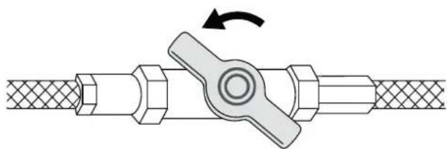
Diagram of a pipe fitting with a valve mechanism, showing rotational motion (no text or symbols)- Open the shut-off devices of the system.
- Start filling by slowly opening the system water fill-up valve outside the unit.
- When water begins to leak from the air vents, close them and continue filling until the expected system pressure value is reached.

Verify the hydraulic tightness of the joints.
It is advisable to repeat this operation after the unit has been operating for a few hours and regularly check the system pressure. Top-ups must be carried out with the machine off (pump OFF).
The system must be filled to a pressure range between 1 and 2 bar.
8.5.2 Draining of the water circuit
- Before starting to load, set the main switch of the system to "off".
- Open the rear inspection panel of the chiller.
- Verify that the drain cocks of the chiller and the system are closed.
- Open all the vent valves of the chiller, the system and the relative terminals.

natural_image
Mechanical diagram of a pipe fitting with a valve mechanism, showing rotational motion (no text or symbols)- Before starting to load, set the main switch of the system to "off".
- Before starting to empty, set the main switch of the system to "off".
- Open the rear inspection panel of the chiller.
- Verify that the system water load/top-up valve is closed.
If the system is supplemented with antifreeze liquids, this should not be drained freely because of pollution. It must be collected and possibly reused.
8.5.3 Exchanger cleaning
The material not trapped by the filters, the water hardness or the high concentration of low freezing point solutions may dirty the water exchangers, reducing the efficiency of the heat exchange.
By using a differential pressure gauge it is possible to check the pressure loss between exchanger inlet and outlet.
If, from an inspection, it is found that the pressure values compromise regular operation or reduce machine efficiency, cleaning the exchanger will be required.
The exchangers must be cleaned with the machine off and by personnel authorised and trained for this type of operation.
The exchangers must be cleaned by using the specific pressure sockets and with specific detergents. At the end of the cleaning operation the exchangers must be appropriately rinsed to prevent detergent from circulating in the system.
At the end of the operation the water system must be reloaded and vented before restarting.
8.6 Refrigerant circuit
8.6.1 Cooling circuit repair
These operations should be carried out only by qualified personnel, using standard techniques typical of cooling systems that use halogen fluids such as refrigerants.
8.6.2 Refrigerant top up
They should be carried out only after having identified and repaired the leaking points.
No more than two top ups are permitted. If an additional top-up is required, the cooling circuit must be emptied completely and filled with virgin refrigerant.
8.7 Decommissioning and disposing
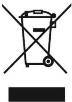
This product falls within the field of application of Directive 2012/19/EU on the management of waste electric and electronic equipment (WEEE).
natural_image
Symbol of a trash bin crossed with a diagonal line, no text or numbers presentThese types of products may contain substances that are potentially harmful to human health and the environment and cannot be disposed of as household waste.
When the machine needs to be replaced or dismantled it must be disposed of according to local regulations on sorted waste, otherwise you must contact your local dealer for information on free pick-up.

FERROLI S.p.A.
Via Ritonda 78/a
37047 San Bonifacio - Verona - ITALY
www.ferroli.com
Made in Italy

- GENERAL 4
- SHIPMENT 8
- COMMISSIONING
- CONTROL PANEL
- MAINTENANCE
- General
- Document information
- Symbols
- Range
- Available versions
- Accessories
- Compliance
- Machine identification
- Intended use
- General precautions
- Basic safety rules
- Residual risk
- Description
- Residual risk near the machine
- Measures to be adopted if refrigerant gas leaks
- First aid measures
- Measures in the event of accidental spillage
- Operations with removed panels
- User guidelines
- Machine description
- Features
- Frame.
- Compressors.
- Fans.
- Condenser.
- Evaporator.
- Electrical board.
- Microprocessor.
- Chiller versions refrigerant circuit.
- Reversible heat pump versions refrigerant circuit.
- Versions water circuit.
- Shipment
- Inspection on receipt
- Position of the equipment
- Equipment
- Storage
- Handling
- Lifting with forks
- Lifting with a crane
- Unpacking
- Access to internal parts
- Resting on the ground
- Installation
- Installation location requirements
- Work fields
- Noise
- Windy areas (Resting on the ground)
- Resting on the ground
- Verifying clearances (clearance area)
- Water connections
- Connection diagram
- Position of connections
- Hydraulic data
- Water volume
- Water features
- Protection against freezing
- Connection to the system
- Models without hydronic kit
- Models with hydronic kit
- System fill-up
- Desuperheater connection
- Electrical connections
- Machine connection
- Connections of the accessories
- Flow switch
- Circulating pump
- External consents
- Connections of the accessories
- Circulating pump
- Commissioning
- Preliminary inspections
- Electrical
- Hydraulic
- Cooling
- First start-up or restart after long inactivity
- Start-up
- Checks during operation
- Pump release procedure
- Shut-down
- Temporary shut-down
- Shut-down for long periods
- Flow rate calibration
- Control Panel
- User interface
- Control panel
- Display
- Function keys
- Switch on and off
- Settings
- Date and time
- Operating mode change
- Set-point
- Unit Status
- Planning
- Alarms
- Alarm presence
- Alarms reset
- Alarms history
- Alarm charts
- Maintenance
- Maintenance
- Weekly checks
- Routine maintenance
- Extraordinary maintenance
- Monthly checks
- Annual checks
- Water circuit
- Water circuit load
- Draining of the water circuit
- Exchanger cleaning
- Refrigerant circuit
- Cooling circuit repair
- Refrigerant top up
- Decommissioning and disposing
Brand : FERROLI
Model : RCA
Category : Pump