
Pegasus D - Boiler FERROLI - Free user manual and instructions
Find the device manual for free Pegasus D FERROLI in PDF.
| Type of product | Heat generator for heating and domestic hot water production (with optional tank) |
| Brand | Ferroli |
| Model | Pegasus D (models 23, 32, 45) |
| Maximum thermal output (heating) | 23.0 to 45.0 kW depending on model |
| Minimum thermal output (heating) | 8.8 to 17.2 kW depending on model |
| Empty weight | 106 to 164 kg depending on model |
| Power supply | 230 V / 50 Hz, 15 W |
| Protection rating | IP X0D |
| Maximum operating pressure heating (PMS) | 6 bar |
| Maximum heating temperature (tmax) | 95 °C |
| Heating temperature adjustment range | 30 to 80 °C (recommended >45 °C) |
| Domestic hot water adjustment range | 10 to 65 °C (with optional tank) |
| Fuels | Natural gas (G20/G25) or LPG (G30/G31) |
| Efficiency at Pmax (80-60 °C) | 90.9 to 91.7% depending on model |
| Efficiency at 30% load | 91.3 to 91.6% |
| Efficiency class (Directive 92/42/EEC) | ★★ |
| NOx emission class | 2 |
| Anti-freeze system | Integrated (active if power and gas supply present) |
| Advanced functions | Evolving temperature with outdoor sensor, time-controlled regulation, self-diagnosis |
| Maintenance | Annual check by qualified technician, cleaning of the boiler body and burners |
Frequently Asked Questions - Pegasus D FERROLI
User questions about Pegasus D FERROLI
0 question about this device. Answer the ones you know or ask your own.
Ask a new question about this device
Download the instructions for your Boiler in PDF format for free! Find your manual Pegasus D - FERROLI and take your electronic device back in hand. On this page are published all the documents necessary for the use of your device. Pegasus D by FERROLI.
USER MANUAL Pegasus D FERROLI
- outweighs the costs of developing and maintaining a new technology.
attraverso ilNumero Verde 800 59 60 40.
- Carefully read and follow the instructions contained in this instruction booklet.
- After boiler installation, inform the user regarding its operation and give him this manual, which is an integral and essential part of the product and must be kept with care for future reference.
- Installation and maintenance must be carried out by professionally qualified personnel, in compliance with the current regulations and according to the manufacturer's instructions. Do not carry out any operation on the sealed control parts.
- Incorrect installation or inadequate maintenance can result in damage or injury. The Manufacturer declines any liability for damage due to errors in installation and use, or failure to follow the instructions.
- Before carrying out any cleaning or maintenance operation, disconnect the unit from the electrical power supply using the switch and/or the special cut-off devices.
- In case of a fault and/or poor operation, deactivate the unit and do not try to repair it or directly intervene. Contact professionally qualified personnel. Any repair/replacement of the products must only be carried out by qualified personnel using original replacement parts. Failure to comply with the above could affect the safety of the unit.
- This unit must only be used for its intended purpose. Any other use is deemed improper and therefore hazardous.
- The packing materials are potentially hazardous and must not be left within the reach of children.
- The unit must not be used by people (including children) with limited physical, sensory or mental abilities or without experience and knowledge of it, unless instructed or supervised in its use by someone responsible for their safety.
- The unit and its accessories must be appropriately disposed of, in compliance with the current regulations.
- The images given in this manual are a simplified representation of the product. In this representation there may be slight and insignificant differences with respect to the product supplied.
2. OPERATING INSTRUCTIONS
2.1 Introduction
Dear Customer:
Thank you for choosing a FERROLI boiler featuring advanced design, cutting-edge technology, high reliability and quality construction. Please read this manual carefully since it provides important information on safe installation, use and maintenance.
PEGASUS D is a high-efficiency heat generator for domestic hot water production (optional) and heating, suitable for operation with blown oil or gas burners. The boiler shell consists of cast-iron elements, assembled with double cones and steel stays. The control system is with microprocessor and digital interface with advanced temperature control functions.

The boiler is arranged for connection to an external storage tank for hot water production (optional). In this manual all the functions relevant to domestic hot water production are only active with the optional hot water tank connected as indicated in sec. 3.3
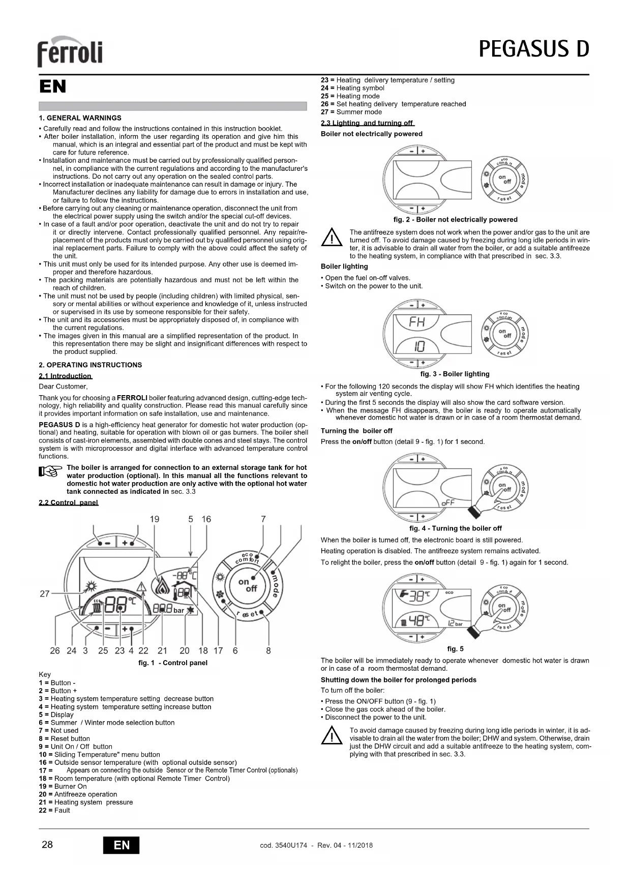
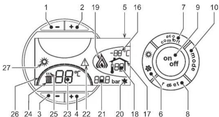
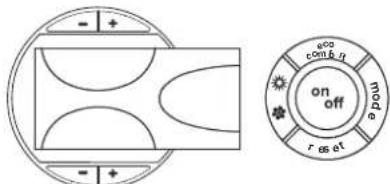
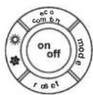
2.2 Control panel
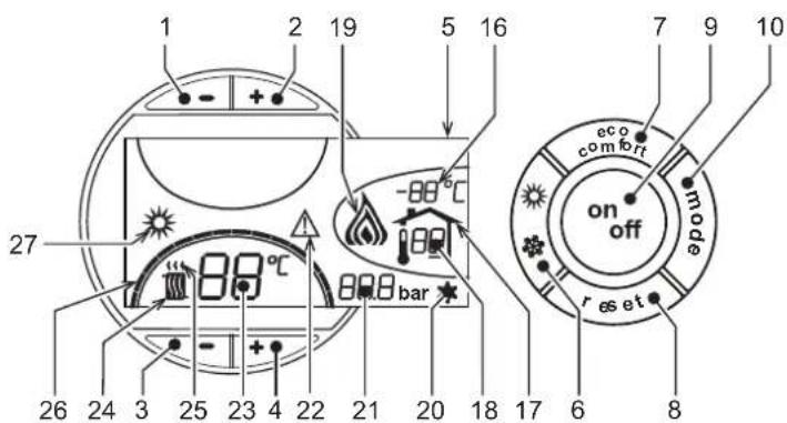
fig.1 - Control panel
Key
1 = Button -
2 = Button +
3 = Heating system temperature setting decrease button
4 = Heating system temperature setting increase button
5=Display
6 = Summer / Winter mode selection button
7 = Not used
8 = Reset button
9 = Unit On / Off button
10 = Sliding Temperature" menu button
16 = Outside sensor temperature (with optional outside sensor)
17 = Appears on connecting the outside Sensor or the Remote Timer Control (optionals)
18 = Room temperature (with optional Remote Timer Control)
19 = Burner On
20 = Antifreeze operation
21 = Heating system pressure
22 = Fault
23 = Heating delivery temperature / setting
24 = Heating symbol
25 = Heating mode
26 = Set heating delivery temperature reached
27 = Summer mode
2.3 Lighting and turning off
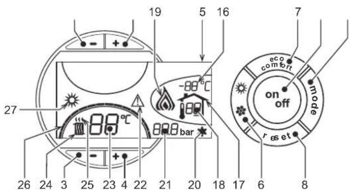
Boller not electrically powered
fig. 2 - Boiler not electrically powered

The antifreeze system does not work when the power and/or gas to the unit are turned off. To avoid damage caused by freezing during long idle periods in winter, it is advisable to drain all water from the boiler, or add a suitable antifreeze to the heating system, in compliance with that prescribed in sec. 3.3.
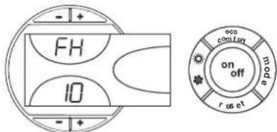
Boiler lighting
- Open the fuel on-off valves.
- Switch on the power to the unit.
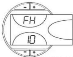
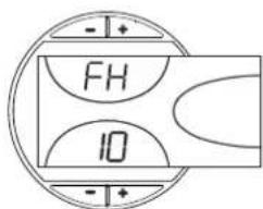
fig. 3 - Boller Lighting
- For the following 120 seconds the display will show FH which identifies the heating system air venting cycle.
- During the first 5 seconds the display will also show the card software version.
- When the message FH disappears, the boiler is ready to operate automatically whenever domestic hot water is drawn or in case of a room thermostat demand.
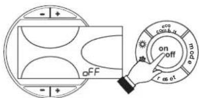
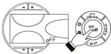
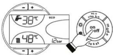
Turning the boiler off
Press the on/off button (detail 9 - fig. 1) for 1 second.
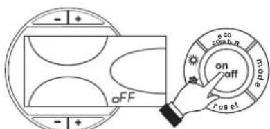
fig. 4 - Turning the boiler off
When the boiler is turned off, the electronic board is still powered.
Heating operation is disabled. The antifreeze system remains activated.
To relight the boiler, press the on/off button (detail 9 - fig. 1) again for 1 second.
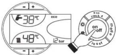
fig.5
The boiler will be immediately ready to operate whenever domestic hot water is drawn or in case of a room thermostat demand.
Shutting down the boiler for prolonged periods
To turn off the boiler:
- Press the ON/OFF button (9 - fig. 1)
- Close the gas cock ahead of the boiler.
- Disconnect the power to the unit.

To avoid damage caused by freezing during long idle periods in winter, it is advisable to drain all the water from the boiler; DHW and system. Otherwise, drain just the DHW circuit and add a suitable antifreeze to the heating system, complying with that prescribed in sec. 3.3.
2.4 Adjustments
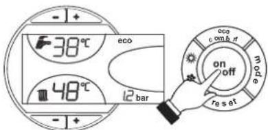
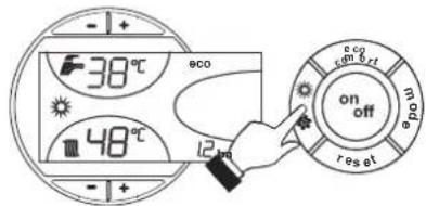
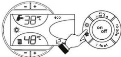
Summer/Winter Swithover
Press the summer/winter button (detail 6 - fig. 1) for 1 second.
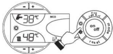
fig. 6
The display activates the Summer symbol (detail 27 - fig. 1): the boiler will only deliver domestic hot water. The antifreeze system remains activated.
To deactivate the Summer mode, press the summer/winter button (part. 6 - fig. 1) again for 1 second.
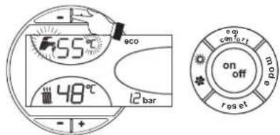
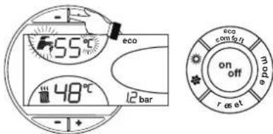
Heating temperature setting
Use the heating buttons (details 3 and 4 - fig. 1) to adjust the temperature from a min. of 30^ to a max. of 80^ .
In any case it is advisable not to operate the boiler below 45^ .
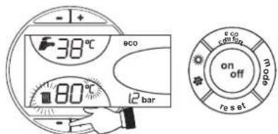
fig.7
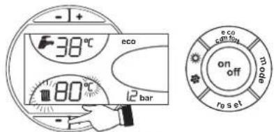
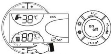
DHW temperature adjustment
Use the DHW buttons + (details 1 and 2 - fig. 1) to adjust the temperature from a min. of 10^ to a max. of 65^ .
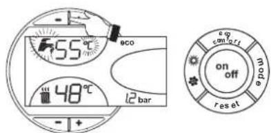
fig.8
Room temperature adjustment (with optional room thermostat)
Using the room thermostat, set the temperature desired in the rooms. If the room thermostat is not installed the boiler will keep the heating system at its setpoint temperature.
Room temperature adjustment (with optional remote timer control)
Using the remote timer control, set the temperature desired in the rooms. The boiler unit will set the system water according to the required room temperature. For information on the remote timer control, please refer to its user's manual.
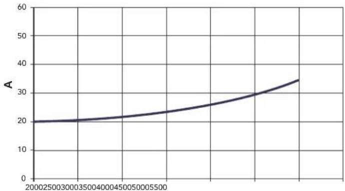
Sliding temperature
When the optional external probe is installed the control panel display (detail 5 - fig. 1) shows the actual outside temperature read by the probe. The boiler control system operates with "Sliding Temperature". In this mode, the temperature of the heating system is adjusted according the outside weather conditions, in order to ensure high comfort and energy saving throughout the year. In particular, as the outside temperature increases, the system delivery temperature is decreased according to a specific "compensation curve".
With Sliding Temperature adjustment, the temperature set with the heating buttons -f+ (details 3 and 4 - fig. 1) becomes the maximum system delivery temperature. It is advisable to set a maximum value to allow system adjustment throughout its useful operating range.
The boiler must be adjusted at the time of installation by qualified personnel. Possible adjustments can in any case be made by the user to improve comfort.
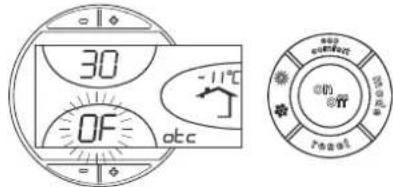
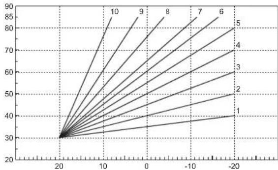
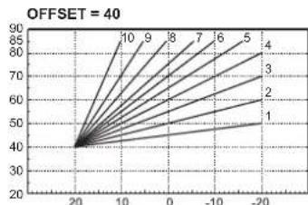
Compensation curve and curve offset
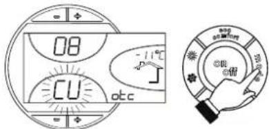
Press the mode button (detail 10 - fig. 1) once to display the actual compensation curve (fig. 9), which can be modified with the DHW buttons (details 1 and 2 - fig. 1).
Adjust the required curve from 1 to 10 according to the characteristic (fig. 11).
By setting the curve to 0, sliding temperature adjustment is disabled.
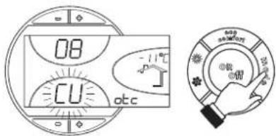
fig.9 - Compensation curve
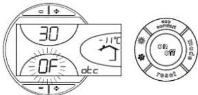
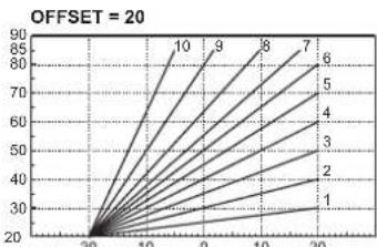
Press the heating buttons (details 3 and 4 - fig.1) to access parallel curve offset (fig. 12), modifiable with the DHW buttons (details 1 and 2 - fig.1).
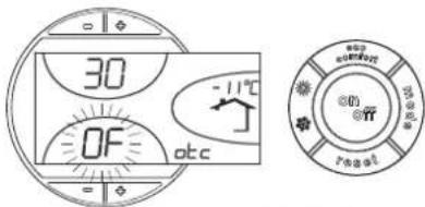
fig. 10 - Curve parallel offset
Press the mode button (detail 10 - fig. 1) again to exit parallel curve adjustment mode. If the room temperature is lower than the required value, it is advisable to set a higher order curve and vice versa. Proceed by increasing or decreasing in steps of one and check the result in the room.
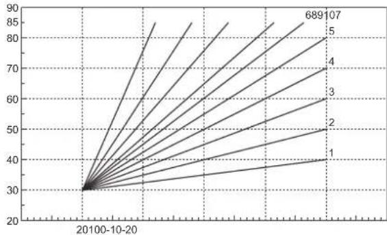
fig. 11 - Compensation curves
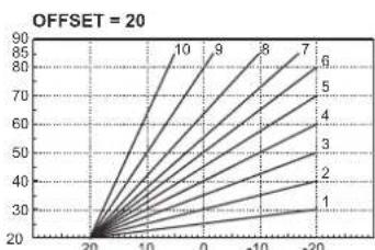
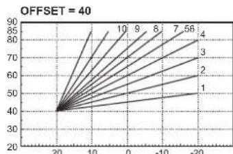
Fig. 12 - Example of compensation parallel curve offset
Adjustments from Remote Timer Control

If the Remote Timer Control (optional) is connected to the boiler, the above adjustments are managed according to that given in table 1. Also, the control panel display (detail 5 - fig. 1) shows the actual room temperature detected by the Remote Timer Control.
Table.1
| Heating temperature setting | Adjustment can be made from the Remote Timer Control menu and the boiler control panel. |
| DHW temperature adjustment | Adjustment can be made from the Remote Timer Control menu and the boiler control panel. |
| Summer/Winter Sustainover | Summer mode has priority over a possible Remote Timer Control heating demand. |
| Eco/Comfort selection | On disabling DHW from the Remote Timer Control menu, the boiler selects the Economy mode. In this condition, the button 7 - fig. 1 on the boiler panel is disabled. |
| On enabling DHW from the Remote Timer Control menu, the boiler selects the Comfort mode. In this condition it is possible select one of the two modes with the button 7 - fig. 1 on the boiler panel. | |
| Sliding Temperature | Both the Remote Timer Control and the boiler card manage Sliding Temperature adjustment: of the two, the Sliding Temperature of the boiler card has priority. |
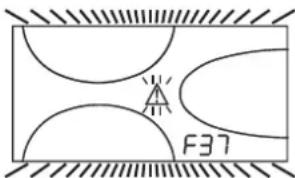
Water system pressure adjustment
The filling pressure with system cold, read on the display, must be approx. 1.0 bar. If the system pressure falls to values below minimum, the boiler card will activate fault F37 (fig. 13).
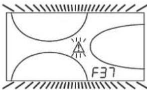
fig. 13 - Low system pressure fault

Once the system pressure is restored, the boiler will activate the 120-second air venting cycle indicated on the display by FH.
3.2 INSTALLATION8
3.1 General Instructions
BOILER INSTALLATION MUST ONLY BE PERFORMED BY QUALIFIED PERSONNEL, IN ACCORDANCE WITH ALL THE INSTRUCTIONS GIVEN IN THIS TECHNICAL MANUAL, THE PROVISIONS OF CURRENT LAW, THE PRESCRIPTIONS OF NATIONAL AND LOCAL STANDARDS AND THE RULES OF PROPER WORKMANSHIP.
3.2 Place of installation
The boiler unit must be installed in a specific room with ventilation openings to the outside as prescribed by current regulations. If there are several burners or suction units that can work together in the same room, the ventilation openings must be sized for simultaneous operation of all the units. The place of installation must be free of flammable materials or objects, corrosive gases, powders or volatile substances that, conveyed by the burner fan, can obstruct the internal lines of the burner or the combustion head. The room must be dry and not exposed to rain, snow or frost.

If the unit is enclosed in a cabinet or mounted alongside, a space must be provided for removing the casing and for normal maintenance operations.
3.3 Plumbing connections
The heating capacity of the unit must be previously established by calculating the building's heat requirement according to the current regulations. The system must be provided with all the components for correct and regular operation. It is advisable to install shutoff valves between the boiler and heating system allowing the boiler to be isolated from the system if necessary.

The safety valve outlet must be connected to a funnel or collection pipe to prevent water spurling onto the floor in case of overpressure in the heating circuit. Otherwise, if the discharge valve cuts in and floods the room, the boiler manufacturer cannot be held liable.
Do not use the water system pipes to earth electrical appliances.
Before installation, carefully wash all the pipes of the system to remove any residuals or impurities that could affect proper operation of the unit.
Carry out the relevant connections according to the diagram in cap. 5.1 and the symbols given on the unit.
Water system characteristics
In the presence of water harder than 25^ Fr (1^ = 10ppm CaCO3), use suitably treated water in order to avoid possible scaling in the boiler. Treatment must not reduce the hardness to values below 15^ (Decree 236/88 for uses of water intended for human consumption). Treatment of the water used is indispensable in case of very large systems or with frequent introduction of replenishing water in the system.

If water softeners are installed at the boiler cold water inlet, make sure not to reduce the water hardness too much, as this could cause early deterioration of the magnesium anode in the hot water tank.
Antifreeze system, antifreeze fluids, additives and inhibitors
The boiler is equipped with an antifreeze system that turns on the boiler in heating mode when the system delivery water temperature falls under 6^ . The device will not come on if the electricity and/or gas supply to the unit are cut off. If it becomes necessary, it is permissible to use antifreeze fluid, additives and inhibitors only if the manufacturer of these fluids or additives guarantees they are suitable for this use and cause no damage to the heat exchanger or other components and/or materials of the boiler unit and system. It is prohibited to use generic antifreeze fluid, additives or inhibitors that are not expressly suited for use in heating systems and compatible with the materials of the boiler unit and system.
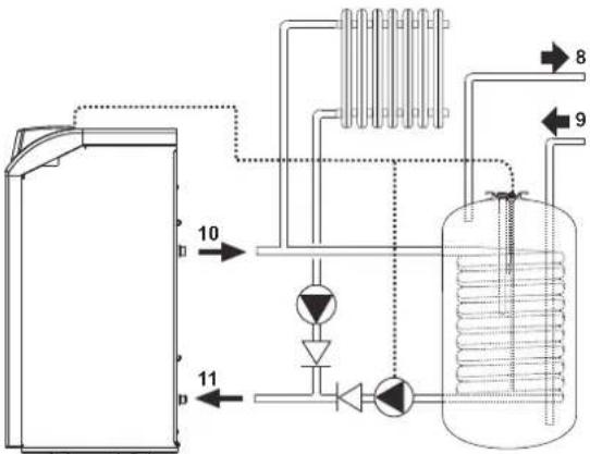
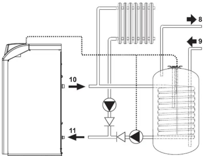
Connection to a storage tank for domestic hot water production
The unit's electronic board is arranged for managing an external storage tank for domestic hot water production. Carry out the plumbing connections according to the diagram fig. 14 (pumps and non-return valves must be supplied separately). Carry out: electrical connections as shown in the wiring diagram i ncap. 5.4. A probe FERROLImust be used. At the next lighting, the boiler's control system recognises the presence of the hot water tank probe and automatically configures the DHW function, activating the display and relevant controls.
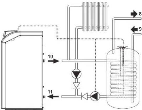
Fig. 14 - Diagram of connection to external hot water tank
Key
8 Domestic hot water outlet
9 Cold water inlet
10 System delivery
11 System return
3.4 Gas connection

Before making the connection, make sure the unit is arranged for operation with the type of fuel available and carefully clean all the system gas pipes to remove any residuals or impurities that could affect proper operation of the boiler.
The gas must be connected to the respective union (see fig. 25) in conformity with current regulations, with a rigid metal pipe or with a continuous surface flexible s/steel tube, installing a gas cock between the system and boiler. Make sure all the gas connections are tight.
The capacity of the gas meter must be sufficient for the simultaneous use of all the appliances connected to it. The diameter of the gas pipe leaving the boiler does not determine the diameter of the pipe between the unit and the meter; it must be chosen according to its length and pressure losses, in conformity with the current regulations.

Do not use the gas pipes to earth electrical appliances.
3.5 Electrical connections
Connection to the electrical grid

The unit's electrical safety is only guaranteed when correctly connected to an efficient earthing system executed according to current safety standards. Have the efficiency and suitability of the earthing system checked by professionally qualified personnel. The manufacturer is not responsible for any damage caused by failure to earth the system. Also make sure that the electrical system is adequate for the maximum power absorbed by the unit, as specified on the boiler dataplate.
The boiler is prewired and provided with a Y-cable and plug for connection to the electricity line. The connections to the grid must be made with a permanent connection and equipped with a bipolar switch whose contacts have a minimum opening of at least 3 mm, interposing fuses of max. 3A between the boiler and the line. It is important to respect the polarities (LINE: brown wire / NEUTRAL: blue wire / EARTH: yellow-green wire) in making connections to the electrical line. During installation or when changing the power cable, the earth wire must be left 2 cm longer than the others.

The user must never change the unit's power cable. If the cable gets damaged, switch off the unit and have it changed solely by professionally qualified personnel. If changing the electric power cable, use solely "HAR H05 VV-F" 3x0.75 mm2 cable with a maximum outside diameter of 8 mm.
Room thermostat (optional)

IMPORTANT: THE ROOM THERMOSTAT MUST HAVE VOLTAGE-FREE CONTACTS. CONNECTING 230 V TO THE ROOM THERMOSTAT TERMINALS WILL PERMANENTLY DAMAGE THE ELECTRONIC BOARD.
When connecting time controls or a timer, do not take the power supply for these devices from their breaking contacts. Their power supply must be by means of direct connection from the mains or with batteries, depending on the kind of device.
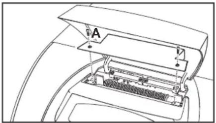
Accessing the electrical terminal block
Undo the two screws "A" located on the top part of the control panel and remove the cover.
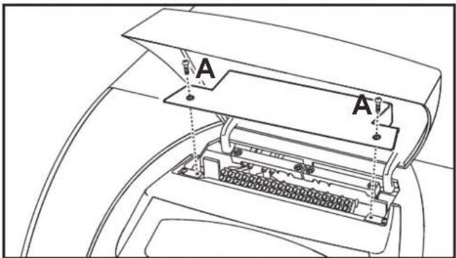
fig. 15 - Accessing the terminal board
3.6 Air/fume ducts
The diameter of the connecting pipe to the flue must not be less than that of the connection on the anti-backflow device. Starting from the anti-backflow device it must have a vertical section at least 50~cm long. The current regulations must be respected regarding the dimensioning and installation of the flues and connection pipe.
The boiler is a B11BS type equipped with a safety device (fume thermostat) that stops the supply of gas and shuts down the unit in case of poor draught or disturbance in the fume exhaust. Unit shutdown is indicated on the display with the code F04 (ref. cap. 3.4). Restarting of the unit occurs automatically 20 minutes after the end of the fault that caused the problem. In case of repeated intervention of the device, contact qualified personnel to check the flue and chimney and eliminate the fume evacuation fault.

This safety device must never be tampered with or deactivated. Any operation on the device, or its replacement, must only be carried out by qualified personnel using the manufacturer's original replacement parts. A functional test must be carried out after any operation on the device.
4. SERVICE AND MAINTENANCE
4.1 Adjustments
All adjustment and conversion operations must be carried out by Qualified Personnel.
The manufacturer declines any liability for damage and/or injury caused by unqualified and unauthorised persons tampering with the unit.
Turning on TEST mode
Press the heating buttons (details 3 and 4 - fig. 1) together for 5 seconds to activate the TEST mode. The boiler lights at the maximum heating power set as described in the following section.
The heating symbol (detail 24 - fig. 1) and DHW symbol (detail 12 - fig. 1) flash on the display.
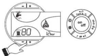
fig.16 - TEST mode
To deactivate the TEST mode, repeat the activation sequence.
The TEST mode is automatically disabled in any case after 15 minutes.
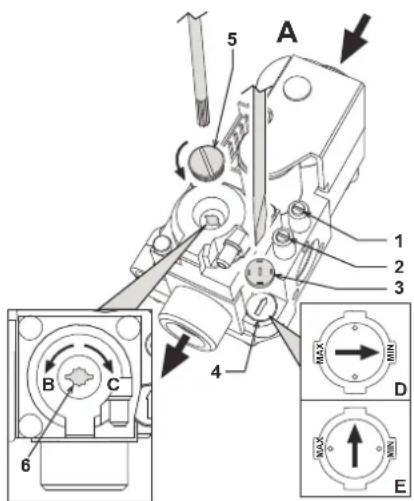
Heating system output adjustment
On PEGASUS D boilers, the firebox heating power and therefore the heat output delivered to the heating water can only be adjusted by means of the main burner through the gas valve, (see fig. 17). The diagrams given in the section cap. 5.2 indicate the variation in heat output delivered to the water according to the change in burner operating pressure. Being able to adjust boiler output to the actual heating requirements means above all reducing heat losses, and therefore obtaining fuel saving. Also, with the variation in output, also regulated by the provisions, the boilers keep their efficiency levels and combustion characteristics practically unchanged
This operation is carried out with the boiler working and the water storage tank heated.
- Using a small screwdriver, remove the secondary operator protection cap 5 of the gas valve of fig. 17.
- Connect a manometer to the pressure point 2 (fig. 17) located below the gas valve, and turn the boiler thermostat knob to the maximum value.
- Adjust the pressure to the required value by means of the screw 6 (fig. 17), referring to the diagrams given in section cap. 5.2.
- Then turn the burner on and off 2 or 3 times by means of the control thermostat and check that the pressure value is that just set; otherwise, another adjustment must be made to bring the pressure to the correct value.
Gas conversion
The unit can work with either Natural gas (G20-G25) or liquefied gas (G30-G31) and is factory-set for use with one of the two gases, as clearly shown on the packing and dataplate. Whenever a different gas to that for which the unit is arranged has to be used, the special conversion kit will be required, proceeding as follows:
- Replace the nozzles at the main burner and pilot burner, fitting the nozzles specified in the technical data table in cap. 5, according to the type of gas used
- Remove the small protection cap 3 (fig. 17) from the gas valve. Using a small screwdriver, adjust the ignition "STEP" for the required gas (G20-G25 position D fig. 17 or G30-G31 position E fig. 17); then refit the cap.
- Adjust the gas pressure at the burner, setting the values given in the technical data table for the type of gas used.
- Apply the sticker contained in the conversion kit, near the dataplate as proof of the conversion.
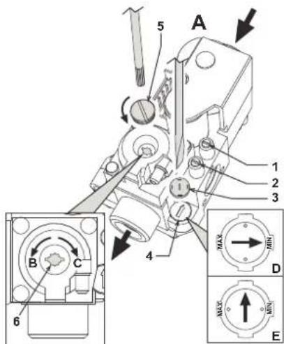
fig. 17 - Pressure adjustment
A Gas valve
B Decrease pressure
C Increase pressure
D Ignition "STEP" adjustment for G20-G25 NATURAL gas
E Ignition step adjustment for G30-G31 LIQUEFIED gas
1 Pressure point upstream
2 Pressure point downstream
3 Protection cap
4 Ignition STEP regulator
5 Protection cap
6 Pressure adjustment screw
4.2 Start-up
System start-up must be carried out by Qualified Personnel. Checks to be made at first lighting and after all maintenance operations that involved disconnecting from the systems or an operation on safety devices or parts of the boiler:
Before lighting the boiler
- Open any on-off valves between the boiler and the systems.
- Check the tightness of the gas system, proceeding with caution and using a soap and water solution to detect any leaks in connections.
- Fill the water system and make sure all air contained in the boiler and system has been vented by opening the air vent valve on the boiler and any vent valves on the system.
- Make sure there are no water leaks in the system, domestic hot water circuits, connections or boiler.
- Check the correct connection of the electrical system.
Make sure the unit is connected to an efficient earthing system. - Make sure there are no flammable liquids or materials in the immediate vicinity of the boiler.
- Vent the air from the gas pipes by means of the gas valve pressure point 1 (fig. 17).
Lighting
Open the fuel on-off valves.
Connect the power to the unit.
For the next 120 seconds the display will show FH which identifies the heating system air venting cycle.
During the first 5 seconds the display will also show the card software release.
When the message FH disappears, the boiler is ready to operate automatically whenever domestic hot water is drawn or in case of a room thermostat demand.

If, after correctly carrying out the lighting procedures, the burners do not light and the message A01 appears on the display, wait about 15 seconds and then press the RESET pushbutton. The reset controller will repeat the lighting cycle. If the burners do not light after several of attempts, consult the "Troubleshooting" section.

In case of a power failure while the boiler is working, the burners will go out and relight automatically when the power is restored.
Checks during operation
Make sure the fuel circuit and water systems are tight.
- Check the efficiency of the flue and fume ducts while the boiler is working.
- Make sure the water is circulating properly between the boiler and the systems.
- Check correct lighting of the boiler, by turning it on and off several times.
- Make sure the fuel consumption indicated on the meter matches that given in the technical data table on cap. 5.3.
- Check the correct delivery of domestic hot water with the t given in the technical data table: do not trust measurements made with empirical systems. The measurement should be made with specific instruments and as close as possible to the boiler, also considering the heat loss from the pipes.
4.3 Maintenance

The following operations must only be carried out by Qualified Personnel.
Seasonal Inspection of the boiler and flue
It is advisable to have the following checks carried out at least once a year:
- The control and safety devices (gas valve, thermostats, etc.) must function correctly.
The fume ducts must be clean and free of obstructions.
The gas and water systems must be tight
The burner and exchanger must be clean. Follow the instructions in the next section.
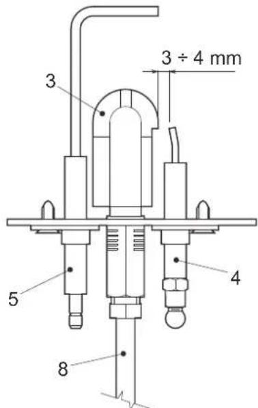
The electrodes must be free of scale and properly positioned (see fig. 21).
- The water pressure in the system when cold must be approx. 1 bar; otherwise bring it to that value.
The expansion tank must be filled.
- The gas flow and pressure must correspond to that given in the respective technical data tables.
The circulating pumps must not be blocked.
Opening the front panel
To open the front panel, see the sequence in fig. 18.
Before carrying out any operation inside the boiler, disconnect the electrical power supply and close the gas cock upstream.
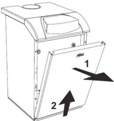
fig. 18 - Front panel opening
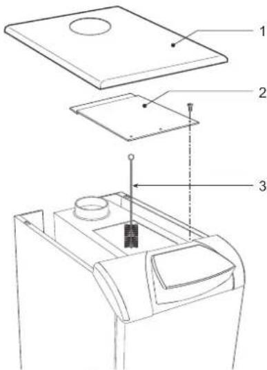
Cleaning the boiler and flue
To clean the boiler properly (fig. 19):
- Close the gas cock ahead of the boiler and disconnect the electrical power.
- Remove the front panel of the boiler
- Lift the casing cover by pressing upwards.
- Remove the insulation placed over the anti-backflow device.
- Remove the fume chamber closing plate
- Remove the burner assembly (see next section).
Clean from the top downwards, using a flue brush. - Clean the fume evacuation ducts between the cast iron elements of the boiler shell with a vacuum cleaner.
- Carefully refit all the previously removed parts and check the tightness of the gas circuit and the combustion ducts.
- During cleaning operations be careful not to damage the fume thermostat bulb at the back of the fume chamber.
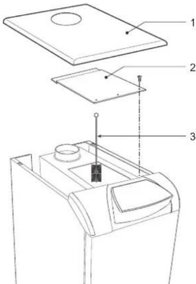
fig. 19 - Boiler cleaning
1 Casing cover
2 Fume chamber closing plate
3 Flue brush
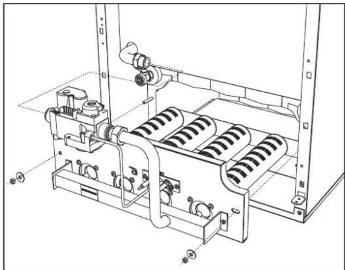
Removing and cleaning the burner assembly
To remove the burner assembly:
- Disconnect the electrical power supply and turn off the gas ahead of the boiler;
- Undo the nut fixing the gas supply pipe ahead of the gas valve;
- Undo the two nuts fixing the combustion chamber door to the cast iron elements of the boiler (fig. 20)
- Remove the burner assembly and combustion chamber door.
Then check and clean the main burners and pilot burner. Use a non-metal brush or compressed air to clean the burners; never use chemical products.
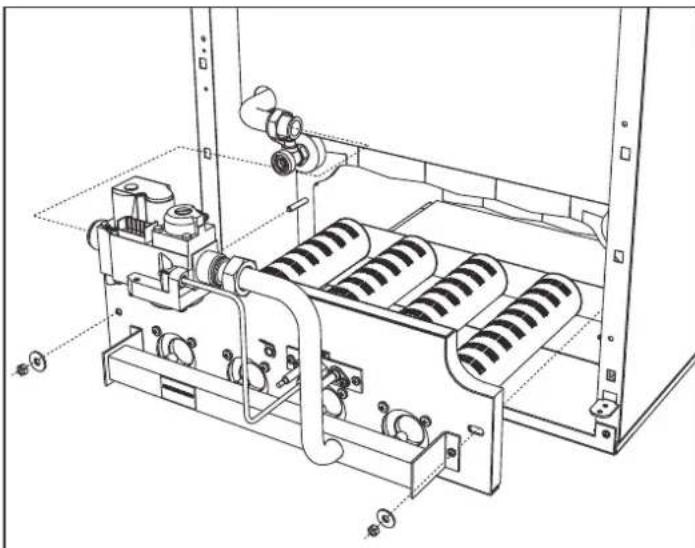
fig. 20 - Removing the burners
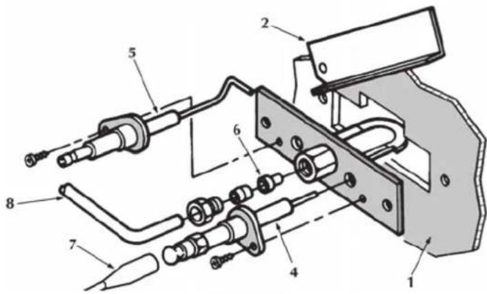
Pilot burner assembly
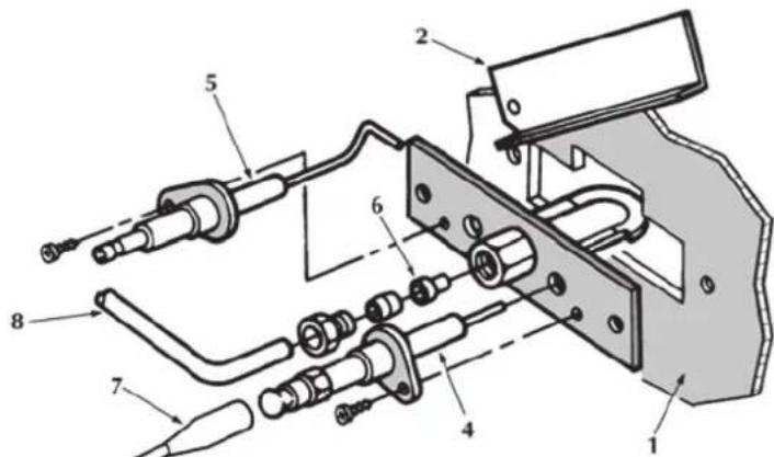
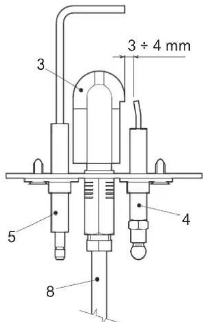
fig.21 - Pilot burner
1 Combustion chamber door
2 Inspection door
3 Pilot burner
4 Ignition electrode
5 Detection electrode
6 Pilot nozzle
7 High voltage cable
8 Gas supply pipe
4.4 Troubleshooting
Diagnostics
The boiler is equipped with an advanced self-diagnosis system. In case of a boiler fault, the display will flash together with the fault symbol (detail 22 - fig. 1) indicating the fault code.
There are faults that cause permanent shutdowns (marked with the letter "A"): to restore operation, press the RESET button (detail 8 - fig. 1) for 1 second or use the RESET on the remote timer control (optional) if installed; if the boiler does not restart, it is necessary to firstly eliminate the fault.
Other faults cause temporary shutdowns (marked with the letter "F") which are automatically reset as soon as the value returns within the boiler's normal working range.
Table.2 - List of faults
| Fault code | Fault Possible cause Cure | ||
| A01 | No burner ignition | No gas | Check the regular gas flow to the boiler and that the air has been eliminated from the pipes |
| Ignition/detection electrode fault | Check the wiring of the electrode and that it is correctly positioned and free of any deposits | ||
| Faulty gas valve | Check the gas valve and replace it if necessary | ||
| Ignition power too low Adjust the ignition power | |||
| A02 | Flame present signal with burner off | Electrode fault Check the ionisation electrode wiring | |
| Card fault Check the card | |||
| A03 | Overtemperature protection activation | Heating sensor damaged | Check the correct positioning and operation of the heating sensor |
| No water circulation in the system | Check the circulating pump | ||
| Air in the system Vent the system | |||
| F04 | Fume thermostat intervention (after intervention of the fume thermostat, boiler operation is prevented for 20 minutes) | Fume thermostat contact open | Check the thermostat |
| Wiring disconnected Check the wiring | |||
| Flue obstructed or not correctly sized | Change the flue | ||
| Wiring fault | Jumper of terminals 12-13 not connected | Check the wiring | |
| A06 | No flame after the ignition phase | Low pressure in the gas system | Check the gas pressure |
| Burner minimum pressure setting | Check the pressures | ||
| F10 | Delivery sensor 1 fault | Sensor damaged | Check the wiring or replace the sensor/Wiring shorted |
| Wiring disconnected | |||
| F14 | Delivery sensor 2 fault | Sensor damaged | Check the wiring or replace the sensor/Wiring shorted |
| Wiring disconnected | |||
| F34 | Supply voltage under 170V | Electric mains trouble Check the electrical system | |
| F35 | Faulty mains frequency Electric mains trouble Check the electrical system | ||
| F37 | Incorrect system water pressure | System empty Fill the system | Check the sensor |
| Water pressure switch damaged or not connected | |||
| F39 | External probe fault | Probe damaged or wiring shorted | Check the wiring or replace the sensor |
| Probe disconnected after activating the sliding temperature | Reconnect the external sensor or disable the sliding temperature | ||
| F40 | Incorrect system water pressure | Pressure too high | Check the system |
| Check the safety valve | |||
| Check the expansion tank | |||
| A41 | Sensor positioning | Delivery sensor disconnected from the pipe | Check the correct positioning and operation of the heating sensor |
| F42 | Heating sensor fault Sensor damaged Replace the sensor | ||
| F47 | System water pressure sensor fault | Wiring disconnected | Check the wiring |
| A48 | Gas valve fault | Gas valve wiring fault Check the wiring | |
| Faulty gas valve Replace the gas valve | |||
| Card fault Replace the card | |||
| A49 | Gas valve fault | Gas valve wiring fault Check the wiring | |
| Faulty gas valve Replace the gas valve | |||
| Card fault Replace the card | |||
5. TECHNICAL DATA AND CHARACTERISTICS
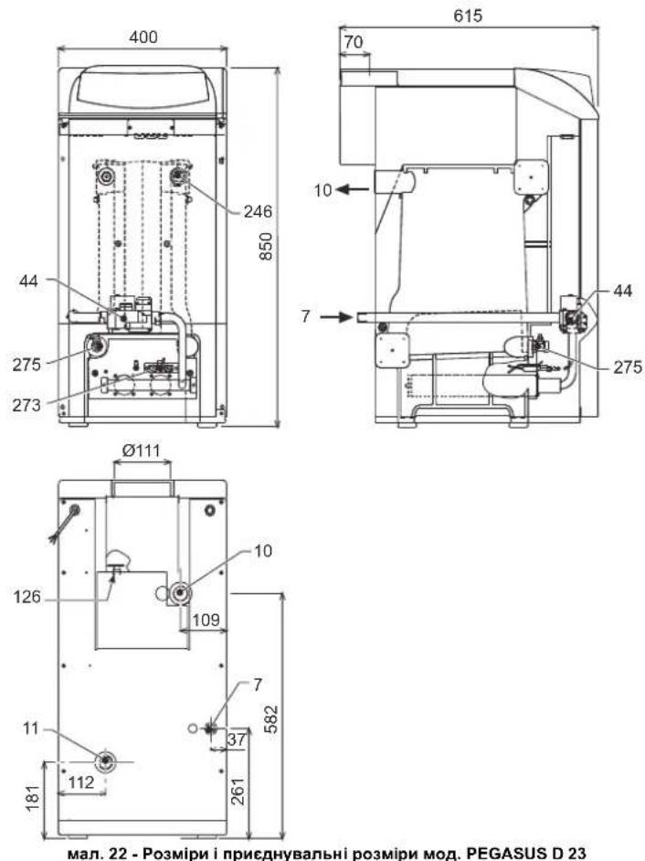
5.1 Dimensions, couplings and main components
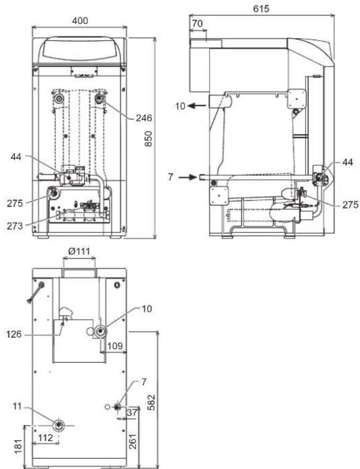
fig. 22 - Dimensions and connections model PEGASUS D 23
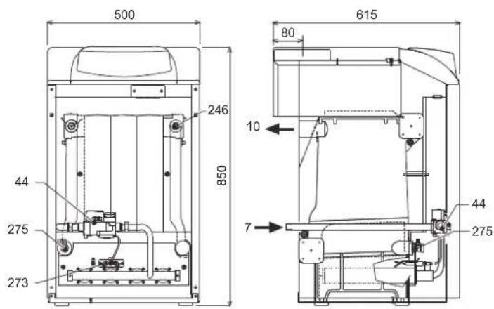
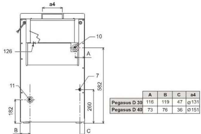
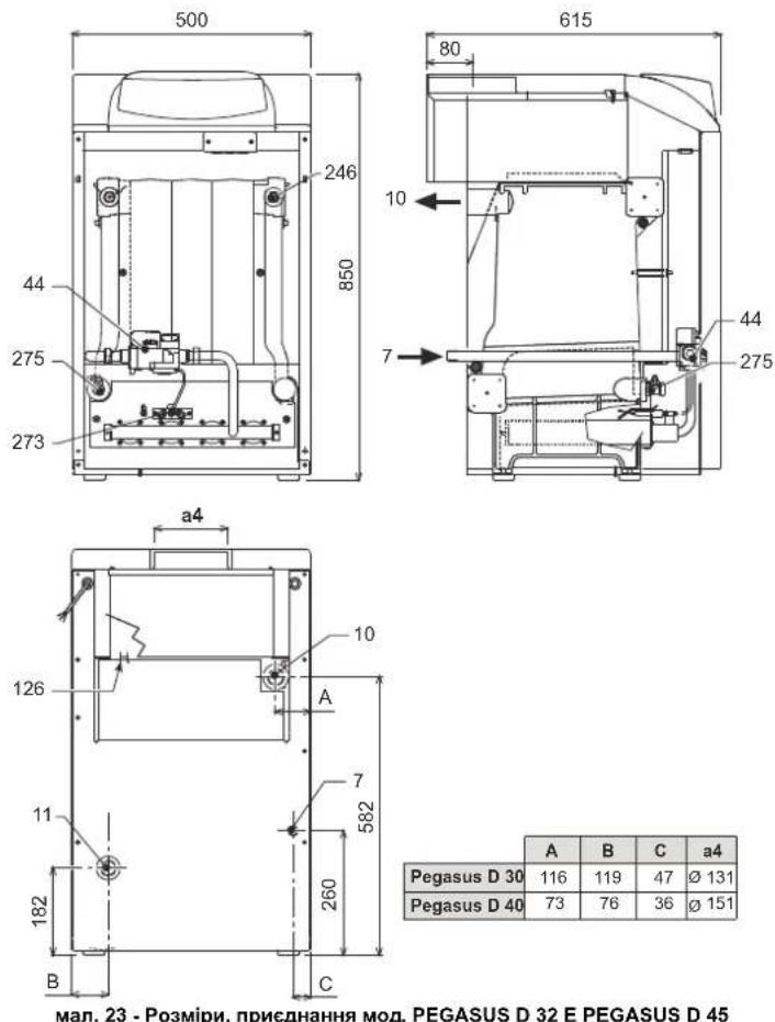
fig. 23 - Dimensions and connections model PEGASUS D 32 and PEGASUS D 45
7 Gas inlet - 0 1/2"
10 System delivery - 0 1" 1/2
11 System return - 0 1" 1/2
44 Gas valve
126 Fume thermostat
246 Pressure transducer
273 Pilot light unit
275 Heating system drain cock
5.2 Loss of head
Pressure loss water side
B
fig.24 - Pressure loss
to mbar
B Flowrate I/h
5.3 Technical data table
| Data | Unit | Value | Value | Value | |
| Models | 23 | 32 | 45 | ||
| Number of elements | kW | 3 | 4 | 5 | |
| Max. heating capacity | kW | 25.3 | 34.9 | 49.5 | (Q) |
| Min. heating capacity | kW | 10.1 | 14.9 | 19.7 | (Q) |
| Max. heat output in heating | kW | 23.0 | 32.0 | 45.0 | (P) |
| Min. heat output in heating | kW | 8.8 | 13.0 | 17.2 | (P) |
| Efficiency Pmax (80-60°C) | % | 90.9 | 91.7 | 90.9 | |
| Efficiency 30% | % | 91.3 | 91.5 | 91.6 | |
| Efficiency class Directive 92/42 EC | ★★ | ||||
| NOx emission class | 2 | 2 | 2 | ||
| Burner nozzles G20 | no. x Ø | 2x2.80 | 3x2.80 | 4x2.80 | |
| Gas supply pressure G20 | mbar | 20 | 20 | 20 | |
| Max. pressure downstream of gas valve G20 | mbar | 15 | 13 | 15 | |
| Min. pressure downstream of gas valve G20 | mbar | 2.5 | 2.5 | 2.5 | |
| Max. gas delivery G20 | m³/h | 2.68 | 3.69 | 5.24 | |
| Min. gas delivery G20 | m³/h | 1.07 | 1.58 | 2.08 | |
| Burner nozzles G31 | no. x Ø | 2x1.75 | 3x1.75 | 4x1.75 | |
| Gas supply pressure G31 | mbar | 37 | 37 | 37 | |
| Max. gas pressure at burner G31 | mbar | 35 | 31 | 35 | |
| Min. gas pressure at burner G31 | mbar | 6 | 6 | 6 | |
| Max. gas delivery G31 | kg/h | 1.98 | 2.73 | 3.88 | |
| Min. gas delivery G31 | kg/h | 0.79 | 1.17 | 1.54 | |
| Fume temperature Pmax | °C | 129 | 130 | 130 | |
| Fume temperature Pmin | °C | 95 | 94 | 95 | |
| Fume flow rate Pmax | g/s | 17.3 | 24.3 | 31.5 | |
| Fume flow rate Pmin | g/s | 15.0 | 23.0 | 28.3 | |
| Max. working pressure in heating | bar | 6 | 6 | 6 | (PMS) |
| Min. working pressure in heating | bar | 0.8 | 0.8 | 0.8 | |
| Max. heating temperature | °C | 95 | 95 | 95 | (tmax) |
| Heating water content | L | 9.1 | 11.6 | 14.1 | |
| Protection rating | IP | XOD | XOD | XOD | |
| Power supply voltage | V/Hz | 230/50 | 230/50 | 230/50 | |
| Electrical power input | W | 15 | 15 | 15 | |
| Empty weight | kg | 106 | 136 | 164 | |
5.4 Wiring diagram
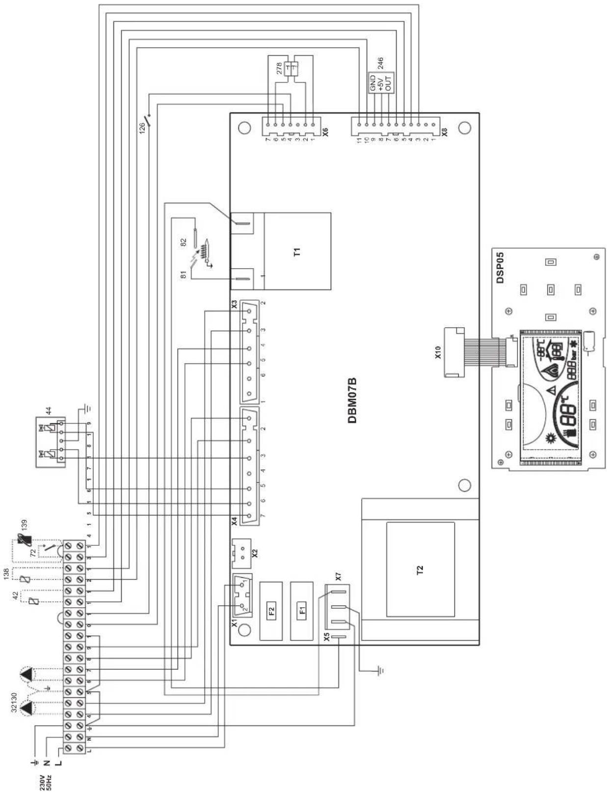
fig. 25 - Wiring diagram
32 Heating circulating pump (optional)
42 DHW temperature probe (optional)
44 Gas valve
72 Room thermostat (not supplied)
81 Ignition electrode
82 Detection electrode
126 Fume thermostat
130 DHW circulating pump (optional)
138 External probe (not supplied)
139 Room unit (not supplied)
246 Pressure transducer
278 Double sensor (Safety + Heating)
FR
1. DISPOSITIONS GÉNÉRALES
3.4 Raccordement gaz

3.5 Raccordements electriques
Ma1.1-PaHEnbKepyBaHHa
YMOBHI NO3HaeyHHA
1= Khonka -
2= Khonka+
3= Khonka 3MeHueHHa 3aHaHOI TEMpepaTyu CnCTeMI ONaJIeHHA
4= Khonka 36ilbweHHa 3daHOI TeMnepaTy y cncTeMI onaneHHA
5= Dnncnnne
6= Khonka Bùbòpy pèxùmy Jìrò/3má - Estate / Inverno
7= He BnKOpNCTOByeTbcra
8= Khonka BiDHOBneHH
9= KHONka yBIMKHeHHBUMKHeHH anapatY
10 = KhoNka MeHIO "3a NOTOCHHO TEMnepaTPOHO
16 = TemnepaTpya 3OBHIHbOro DaTynka (3 ONuiHIM 3OBHIHIM 3OHDOM)
17 = 3'ABNCTCBP npn nniHCHHHO3OBHIHBORO 3OHy a60 DnCTAHINHO xPOHOCTAY (noCTaAOTbCA OKPEMO)
18 = Temnepatypa habkONHbOre cepoDBNua (3 onuiHIM DnCTAHJINHM xpoHOCTaOM)
19= IHdkauiyBIMKHeHOro naIbHnKa
20= Hdkaia npaioqOHO aHTnΦp3y
21= INdkauiz Tncky y cncTeMI onaneHH
22= INdkauie Henoaikn
23= YctaHObKa / TemnepaTypa npMoI NiHII onaneHHA
24= N03haHka onaeneHHA
25= INdkaizipnaqioyoro onaneHH
26= INnkaia DOcRHeHHa daHOI Tempepatyn npmoi NiHII onaneHHA
27= INdkauiapekmyIto-Estate
2.3 YbIMKHeHHH i BmMkaHH
HaKoTeHneNoaTbcraeneKTPnueKHBnEHH
man.2-HaKoTeHneNoaTbcEneKtpuHcKHBnEHHa
KIO eNekTPnHHe KINBENHH I/ABo Ra3 He NODAOTbC H Anapat, CNTEMA ANTHPPNHY He npaIOE. KIO Bu Hc KOpNCTyBATMMEcER cKOTNM BNPoD0BX TPNBaIoro Yacy B3NNMy, ToDI, IO6 3ano6ITn Noro yUkOJKeHHIO uepe3 3amep3AHH, PekOMeHNDyTcB3NITN BCOY BO3 KOTNA, ABO YEcTN pnpCaKDpyno 3AmeP3AHH B KOHTyp BiIDNOBIDHO DO BKASIOK 3 SEZ.3.3.
YbIMKHeHH KOTna
BikpnTe BicciHi KnanaH naIbA.
- IpaIte eNEKTPnHHe KMBneHHHa arperaT.
MAN.3-YBIMKHeHHKOTnA
IpoTROM HACTYNHN 120 CekHyHn Da HcNnei 3'ABNTbcr FH, kA no3Haae cKKn KcHdHHa NOBTPra KOHTyPa OpaENHn.
IpoTAROM nepuix 5 ckyHn Ha nncnei3'ABITcra TAOK Bepci I3 eNEKTOHOI pntai.
PcH3HKeHHHaHcy FHI KOten Byde roTOBmIyHKIOHyBAtn aBTOMaTHO KOKHOPOa, KOJIb OeepCTPOBAHO CNOKMBAHrRAPaHOCAHTEXHHoBOJn 60a H3aNTIMKIMATHOROpTePMoCTATA.
BumKHeHHKOtNa
HaTnCHiB KhoNkY on/off (no3.9 - Man.1) Ha 1 cekyHdy.
man.4-BmKHeHHKoTna
Habib y BIMKHEHOMy KOJIi ENEKTPUHHe KJMBEHHAe noaETbcra Ha eNekTPOHHy nNaTy.
OnaneHHBumKHeHe.Cntema npoTn 3aMeP3aHn npoDobxye npaOBoATn.
JNROBTOPOHO YBIKMHHHNR KOTNA 3HOBY HATCHITb KHONKY ON/off (yBMKH/BMMKH) (NO3.9-MAN.1) Ha 1 CEKYYDA.
man.5
KOTENOTOBINo pO60TN KOKHORPOa3y.KONBID6yBaETbCBAID6ip rapaoyBOAn a60 noCTynae 3anNT BID KIMHATHORO TepMOCTATA.
TpBaJIe BUMKHeHH KOTJa
BIMKHeHHKOTNa Heo6xidHO
HaTHCHYTN KHONKY BBIMKHEHHBIMKHEHHN ON/OFF (9-Ma1.1)
3akpuTu ra3OBuB BeHTunb Ha noaayi r3y y koteI.
Bid'edHaTn Koten BID eNekTpomepeksi
A 阿KIO Bn HE KOPNCTYBaTMETECK KOITNOB BNPoOBK TPNBANORO YACY B3MKNy, ToDJI, 063aONOBiTNIHOYOUKOJXeHHIOyepe33aMEp3AHH, peKOMEHdyETcBcA 3NNTN BCO BOY D3 KOITNA - JK 3 KOHTpy rapHOrO BOONoCTaAHHRA, TAK I 3 KOHTpy OAnEHH. a60 3NtN NIIWE BOY DnI TBN Ta BBeCTN BiNDnBHy npICaNky pOToN 3aMeP3AHHBA KHTpy OAnEHH, 3a HOpMaJIeO 3BepHbCBA do sez.3.3.
2.4 PerylkuBaHHa
NepemkkannJito/3nMa
HaTnCHiB Ha KHONky estate/inverno (nito/3ma) (no3.6-Man.1) Ha 1 cekyHny.
man.6
Ha nncne 3aogopctbocn no3hauka nita - Estate (no3.27 - man. 1): KOTEN npauoBauHIME
nue ha npotybaancaHTexhihoBoDn. Pekm pOToN cnCTemn npToN zamep3HHA
3aHnactbck AKTINBOAHIM.
Uo6 yBIMKHytn peKMM Estate (nita), HATNCITb 3HOBy Ha KHONky estate/inverno (nro/ 3ma) (no3.6 - Man.1) Ha 1 ceKyHdy.
PerynboHHa TemnepaTpy onanenHH
BnKOpNCTOByTe KhONKn OanEnHn (no3. 3 Ta 4- Man. 1) DnR 3mHi N TeMnepaTyPi BId MinImaiNbHOI 30°C Do MaKcIMAmNbHOI 80°C.
Mn paIMo He KopncTyBaTncr KOTnOM npu Tempepatyi HxKHe 3a 45^
man.7
PeryIIOBaHHaTeMnepaTpyrnapaO caHTexHIO BODN
KhONkAMn onaneHHra-4+ (no3.1i2-MaJ.1)MOxHa 3MmHTn Temnepatpy BiD MINImanbHoi 10^ do MAKcunmanbHoi y 65^
man.8
Peryiobahn KIMhaTHOI TEMnepaTyPi (BMOHTOBAHM KIMHATHM TepMoCTaTOM)
3a Donomoro KIMHATHORO TEPMOCTATA BCTAHOBIT 6aKaHJy TEMNEPATpy y npnMIueHHI. PnB DcTyHOCTI KIMHATHORO TEPMOCTATA KOENT 3a6e3neye neTpmaHHY CNTeMI TEMNPEPTPO 3a4dHOY cTahAOBH NprrnMoJIHHCtEMMe.
PerynoBaHHaKimHaiTeMnepaTyPi (3a DonomoroHO DnctahuiHoro xpoHOCTaty -Onu)
3a Donomoroo DnctahuiHoro xpoHOCTaty BCTAHOBiB 6aKaHy Temnepatypy y npMiuHHI. Koten perynoBATME BOy UcTAHOBNI B 3aneKHOCTI BiD 6aKaHOI TEmpePATyn y npMiuHHI. IIOO poobOTn C nCTAHUIHIMM XPOHOCTaOM, 3eBHPCo DO BIINOBIHIOH INCTPCKU KOPNCTYBAHA.
Pyxoma notocha temnepayps
KoN BCTaHOHIOCTbC3OBIHIHII 3OHd (3a OKPMM 3AMOBNEHHM), Ha DCINNEI naHENI KOHAD (n03.5 - MAJ). 1'3BIAETbC NTOHNA 3OBIHIHUN TEMEPATyPA, 3AMIPHA CAMM 3OBIHIM DaTHKOM-3OHDM.CNTEMA peryNIBOHAN KOTNa npAIOe "3a NOTOHOO TEMEPATyoHO". Y cyMOy pexMI M TEmEPATyCA HCTEMN OAnEHNE TPEYNOCTcB 3aENXHO BID 3OBIHIIX KIMATMHHX yMOB, 106 rapaHTyBaTN iNDbuHEHN KOMΦOPT Ta 3aOuaDAxHHe HEPRII HA nPOTRi CYBOPOK. 3OKPMA, pnN DIBuHEHN 3OBIHIHBo TEMEPATyPN 3HNKcyTcBA TEmEPATy y TPsyBOPOBIOndaH BOIN y CNTTEMY OAnEHHRA, 3aENXHO BID KOHKPeTHOI KOMNECAUHIO KpINOBI".
Pn peryunobHH "3a notooho TEMpepaTpoio" TEMpepaTpa, 3aanda KHonkamn OanelenH -/+ (no3. 3 Ta 4-Man.1) ctaHOBtMHe MaksimbanHy TEmpepatoy y TpybONpOBoi NDaI body y cStcEmy OanelenH. Mn paJIMMo 3aadin MaksimbanHe 3aueH, uO6 peryunobHH y cStcEmy npOboDmncy y BcOmy poOohmy dianaoHi.
KotelMac6yTBIpeYIbOBAHO KBAIipikOBAHMMpaxiBmHa etani MoTHaxy.DnpiNIMUeHHKOMFopTyKOpCTyBaMooze3pOHTu DeKei DoBeHHe.
KomneHcauiHa KpBa Ta nepeMeiueHH KpBHX
PnnoNtOBTHOMy HATNNKcHHi HA KHONKy peKIMMy (no3.10 - Man.1) 3'ABNTBcN NOOTCHa KOMNEHCauHHa KPbA (MaJ.9), RXY MOKHs3MHHOBAtu KHONkAMN CNTEMF TBN (no3.1ra2-Man.1). BIDperynlte6kany Kpny B Mekxaz 3aueHb Bid 1 do 10, 3aIeKHO Bid xapakTepeHCTNIK (man.11).
PnBCTaHOBHeHH KpNBoI Ha O peryuKoBaHHa 3a noTOUHO TEMnepaTPO bye cKaocBaHe.

Ma9- KomnHcauiHa KpuBa
Пин Hatнckанни Кнонко aneHн (no3.3 ta 4 - Man.1) Hanaetbca Doctyndo napanbelhoro nepemileuhen KpBnX (man.12),Яke moKHs3mHOBaTN 3a donOMorHO KOHNOK CNTeMn FBN (no3.1 ta 2 - Man.1).
Ma1. 10 -NapaneIbHe nepemieHnKPNBnX
PnnoBtropHomHaTnckaHHi KaHONky pexmy (no3.10-mal.1) 3a6e3neuyetbcra Bxix3pexmyperynkOBAHnpanepbHexKpBHX.
KyuTo TemnepaTy p npmiueHHc HNkOo 3a 6bKaHe 3HaehHMy, Mn paHMo BCTaHOBHT KPNBY BmUO NOpAky, Ta HnAbKn. 35InbUyte a0o 3MeHsuYte 3Haehuy HA OAnHIOu, nepeBipJNOy pezIbTat B OTOQyOHMy CpeDobuHi.
He BUKOPNCTOByTE Tpy6n BO4Hnx CnCTEM AK 3a3emHeHH eNEKTPuHNX npnnd.
Ipeed moTaxem petenbno npomnne yci TpybnpoBOn CNCTeMn, 06 BnAaNTN Ocaan 3abpydHeHHa, aKIMorHn 6 3abaNTn npabunbni pobotaraty.
BHKOHaTe NiKIOHcHHo BoiNobIHx WtUepi 3iHO MaIOHky , HabeJeHOMy y cap.5.1 Ta i no3HaKam Ha camomy arperati.
XapakTepeCTNKBODN B KOHTpy onaJIeHHA
KIOO JOKCTKICTb BOnu npeBnUc 25° Fr (1°F = 10 uactHn Ha mInioh CaCO3), ToDi, Oo3 3anobirn yTBPoehHHo HAKNY u KOTNI, Heo6xioHO BnKOpNCTOByBatn CneuaianHo 6op6nEHy BOy. B pe3ynbati O6p6kn JOKCTKICTb Mae 6ytN He HNkOHO 3a 15°F (Dekpt Ppe3nDEHTIaIIncbKO PeCny6nIK 236/88 0do BoHN BmNBAHNR BOIN Dnna NtHORO N o6byTOBO rnp3NaHeHH). O6p6Ka BOnu e 06oB'3KOBO B noWupEnHX CNCTEmax, A60 npu cactnx yBeDeHHX BOnu ta II NOBepTaB b KOHTyp.

Y pasi yctaHOBN npCTPOO DnB BuaIeHn BANHnHex peOBHN Ha BXoI XONODHO BOH Do KOITNa, CNIkyte 3a TmN, O6E He dyke 3MeHUnT nCTyneHB JOKOPCTKCI, TOMy IO MOKE BnBbNTncb nepeDaHa DeCtpKyJi MarHicBORO AHOdy BoInepa.
Cnctema 3axncty BiD 3amep3aHn, aHTnΦpn3n, do6aBKn Ta iHri6itopn
Koten obnaHano cTeCTMO 3axnCTy Bid 3amep3aHH, kna nepeBONTb KOTEN y pexmN nirpiy, kya ToemepaTpy BOnD y nkiOHeHH CNTeM i naae HnKue 6^ Lcien npctrHne He die npri BIDKIOHNeHH IeneKTPOXBNHeHH i/a6o nodaH rasy y KOTen. B pasi Heo6xIHOCTI donyckaetbca 3actocobyBann aHTnp43i, doBADok i HrbiotipB, ane nIwse i BnKIOHoo, kyaIO BnIOb6NHk TAKHX aHTnp3iB 60doBADok HDAe rapaHTIO, kya 3a6e3neVye, uno Noto PNDyUckni PnDAtn Da TAKO BRKOpCTAHN i He 3aBdac NowKOJdHb TEnNOo6MIHNKHy A60 IHsIM KOMNoHEHTAM i/a6o MATEpianAM KOTaN i CNTeMM. 3a6OpOHETCBa BRKOpCTOBYBATn aHTnp3n, doBADKN i Hrbiotip, kki He npndtHi cneJIaBnHO nra BNKOpCTAHN y TENIOBnx CNTeMAX i Hecymichi 3 MATEpianAM KOTaN i CNTeMM.
PiEaHnHDo6oHnepyDnraPaeoCaTExHIOBou
EEnKpOHHa nnata KOTna npn3aHHe nIg KepyBaHH 30BHIuHM 6oJIePOM dN BINO6HNTBa rapiOy caHTexHiO HbDN BkoKaHte iDpOExTHNI iNkIOeHHN 3rIHO cXMeM Man.14 (HACOs T a 3BOPOTHI KNANAH MAOTb NOCTaATNC OKPMo). BKOHaIte: eNKeTPuHi NIDKnIOUeHHN 3rIHO do eNKeTPuHi cXeMH Ha cap.5.4 Mac BKNOPcHbTOByaTHC DaaH-3oHD FERROLI.CINCTema KEpyBaHH KOTla, nId hAc HAcTynHoro 3anycky, PO3nHaac 3oHd BoIIepey Ta abTomAtMuHO BCTaHOBIOne napAemptn, yBIMKhYbUs mDCnNe t BIAOBINK KOHMAnfФyHKuI IFBN.
man.14-Cxema nID'cDHaHHa 30BHIHbOro 6oJIepa
YMOBHI No3HaueHHA
8 Buxid rapaoi caHTexHIOI BOIN
9 Bxid xoJIOHOI caHTexHIOI BOIN
10 Ppma nihia (harHtAHHa) KOHTpy onaneHHA
11 3bopotha nihia KOHTpy onaneHH
3.4Пдкнluоунгra3y

Ipee TIm, JK 3dIiCNTHn iNkIOHcHHe, nepeBIPte, 0o aeratr pnpaTnn Dopo6OTn Ha daHomy BHy napbHO, Oocnttbc bC tpyb nn rnya B CNTem 3 MeTOK BuDAnEHNEO cAsd (XIK MOxytb 3BaADmtn cnpabHn po60ti KOTna).
Nikoyehra3y Mae 3iChOBATncb Do BIDNOBHorO nEHaHHa (nB. Man. 25). 3fIOHOHOPMAHNB, 3A DOMONORO KOPCKoi METANEBOI TPy6n afo HuyKO tpy6n, h CTHI 3 HejPKABHO CIANI, BCTAHOBIOHQ RAOONB BEHTINB MIX CNTEmoTO Ta KOTNM.NpekoahTecy y mblhocTI rAOONs
Cnpomokhictb razoboro nihnhka Mae 6ytn doctathboo dno NDohocchoro Bwnopctanha BCix arperatib, kio hboro n'denahi. Diametp buxodnoi 3 Kotna Tpybn da rasy He cnlnbac Ha Bvip diametpy Tpybn mix arperatom Ta nihnhknom; Horo cnid Bvpatn B3anejxhocti Bid DOBXHN Ta BtpaH nanopy, BiDnOBIDHO do DIOHXN HOPMaNBIB.

He BnKOpncTOBnyTe Tpy6n dnaTg r3ay k3aemneHH eneKtpuHnx npnad.
3.5 EneKtpnHi 3'cDHaHn
PiknouenHa o enektpuHoi Mepeki

EneKtpnHa 63neKa npnaNy 3a6e3neUyctbca TInk 3a yMOBN Ioro npabNtBHO rIKKnOHeHHr DO eFeKTHBOH CICTEM 3a3eMNEHH, BVKHOHOrI BIDNOIBIO Do YNHHX HOpm 3aKOHODABCTBa. EfeKTHNBICTb Ta BIDNOIHCTb CNTEM 3a3eMNEHH Mac nepeBipTnCA NIIue fXibUIMM, BIP06NHK BIXINIE 6yb-ky BiNDOBdANbHCTb 3a MoKNBI 3bNTKN BHCNIOK BIDCYTOCTI CNTEM 3a3eMNEHH Heo6xHIO NepeBipNTn TAKOK, IO6 eEKeTPnHa CNTEma BiNDOBdANA MaKcImMaBHi NOTyKHCTi, CNOXHBAHI arperatOM. Lg 3Haehn BkA3aHe 3aBoDcSi KaTbnQoi KOTNA.
Inpi niknoenH Do mepexi enektpnHoro jxnbneHH KOTEN noCTaaytBc3 nIIOROBOAHm ENeKTPNHM KAbemem Tny "Y" , He OCHAeHHM BNKIOHO .IIINKOHOHH Do mepexi NOBHNI MAtn FIKCOBAHe 3ECDHnA Ta BOONIOCHN NpeMnKAu 3 BIDCTAHNO MIX KOHTAKMa UOHaUMeHH 3 MM, POStaUoBYOn 3An06BHKnHa Ha 3A MIX KOTNOM Ta IINlEO Pn iNknoehHH Do mepexi enektpnHoro jxnbneHH BaxnIMBO DOpMYBATNC nonPnHOsti (IIHIR: KOPKHeHH Kaeb / HEITPAb; CnHI KABe/ 3EMNJ: KObTO-3eHNH KAben).PiD Yac MOHTaxy afo 3AmHn KaebIO XJbnEHH H Heo6XJHO 3aANWHTN pOBiHN 3a3EMNEHH Na 2 CM DOBWM y npOBHHa 3 IIUMM.

B KOMTeneHJIO KOpNCyBaVa He BxOoNtB 3aMiHa Ka6eIIO KInBHeHHa Y paiaYbIKoDKeHHa Ka6eIIO BIMKHiB arperat,NOTIM 3eepHItcB NO DOnOMORY DOKanlIOBAHO raxiuey BNnAky 3aMIHn EJeKTPhHO R Ka6eIIO KInBHeHHa BIKOPCtBOte BKNHIOKa6eIIO HAR H05 VV-F" 3× 0,75 MM23MAKCNMaBnHM 3OBHIuHIM diametpom 8 MM.
KIMHATNII TepMoCTaT (oncia)

YBAFA: KIMHATHNI TEPMOCTAT NOBINEH MATN BILbHI KOHTAKTN. NIKHOUYOCH 230 B DO KJEM KIMHATHOFO TEPMOCTATY, BN BE3NOBOPOTBO 3AUKOJNTE EJEKTOPOHYI NATY.
Pn iNIOIOHHe HxpoHOCTaB aOToHMepy He 6epiB XNBEHnHn DnI cx nnpCtPOB 3o pO3MNIAOOHX KOHTAKTB. 3a6e3neueHHn ix XNBEHnHM NOBHnHO npoBOHNTcAyepe3 6BeIOOEpeHn NiEcdHaHHo MepeXi aO b0a3a DonOMOrIO BatapeB, B3aneKHOCTB1 Bi Tny arperata.
BIDRBNTITb DBA RBNHTN "A" 3Bepxu TtKa Ta BnDanltb Kpnsky.
MaJI.15-DocTyndoKlEmHoI Kopo6Kn
3.6Pi'cHaHHoDAMOXOy
3cDHaHn Tpy6n 3 Tpy6o0 NOBHHM MaTH DiAMTp He MeHue, HIX Ha yctaHOBJI.
TouHHaOHn 3 AHTN NOBHm6yTN BePTKAnbHm PO3p3 3ABDOBKKn HE MEHue NIBMetpa.
UO CTocycTeCB 3oP3MIPiY cTAYOBKY dmoXoJb i CNOyHOrO Tpy6oPBOy Do HIX, HEO6xIDIO BINOBADttn CTAndaptm.
KoteI MaC B11BS TnIy i Ochauhen 3anobixHHM npHCTpoem (TePMocT aDMOBHX raib), taK Ye npOuyntb noaHry raby i yunHre poBOTy npHCTPOO b pasi noraHoro npoeK TY a60 npOyuHHe HPO3p4y npOoYkTB 3rOPOHN. BnOK npHCTPOO bIDo6paxactbca HA dncnnei 3 KOdom F04 (Dn. 3.4). Pepe3anyck 6bOky ABToMaTHIO nicr20 xBNHIN 3 MOMHTy 3aikHeHHB HIN, 0o BNKnKAno npObLemy. y pasi nobTOPHNX BTPyAhbnpHCTpo, 3BepHIb8do KBaIIipIKOBaHO rEPcoHany nepeBipTN KAMH i DmAp i 3aONBHIn THedonik npOdyBKN.
Lepnctpi 63neKNIHIO NEOBHHI 6yTN iNpO6NeHI a60 BiKIOHcHI. Bci poBOn NO BIAHTYBAHHO a60 NfO 3aMHa NOBHHA BIKOHByATmC TINbK KANIDIKOBAHM nepcohanom 3 BKNOPCTAHRM OPIIHbHx 3anaCHX qACTHN BPO6Hka. Heo6xdHcTB E'JNA BIKOHAHHTECTOBOR nporHOY icKONBOBTPyAHHn ha di spositivo.
4. EKCNJYATAUi I TEXHlHE OBCJLYROBYAHHu
4.1 PervnoBaHHa
Bci onepaui 3 hanauybaHH Ta nepehaIarOkeHH MaOt b BkoHyaTcra TinbKn axibum 3 nepebipeHO KBaIicipiaucio.
BnO6Hn Bixn8 6yIb-ky BiNIOBiaIbnHCTb 3a NooKoKeHHM MaHai/a60 TpaBMn BhaCIIOK yuKOKeHH KOTNa oocamn, kIe H MaHOt b IBDnoBHOI KBAIipikaT Ta BNOBHOBaHexb.
YbIMKHeHH TectoBOro pexmmy TEST
HaTNCHtB ODHoACHO KHONK onaneHHN (no3. Ta4 - Man. 1) Ha 5 cekyHd, o6b yBMkHTn TectOBIN peXm TEST. Koten po3nAIOeTcB npM kACmAbhni noTyKHOCTI dna onaneHHN, BCTAHOBneHn erIgIDHO KaBIAIOK HAcTyHnOr naparpaFy.
Ha dncnnei 6IIMATMMyb no3HaKIn onaneHHra (no3.24 - man.1) i caHTexHIOBdo (no3.12 - man.1).

MaI.16 - TectOBH pexHM TEST
IINBIMKHeHHpeXMy TEST noBtOHTe NocniIOBHCb onepaui, k dnnyBIMKHeHH.
YBCaKOMypa3ipeKIMTESTABTOMaTHNOBIMNKactbcepe315XbHHN.
PerynIOBaHH noTyKHOCTI onAnIOBaNbHOro KOHTpy
YKOTnax PEGASUS DMOxHa peryIobatn TennocMHCTb Kamep 3ropHnra Ta Hacnipok, TENNOBY NOTyHKHCTb, Ia KpepeAteb BODi Dn anaJehnra Dnue bOro DOctAthBo HanaTByBn rONOBH nAnbHk, Uepe3raOboN klanan, (DVB. Man. 17). Ha diarpamX nparapardcap.5.2 B4aoybCpe npenadyn YtneBnO notyKHOCT, Ia KpepeAcBc BOi npn 3mIHIOBHH pOboOTO rCKy Dn naBnHka. MoKInBCTb HanaTByBn NotyKHiCTb KOTNa BiNDIOHO de peabHnx NopTi6 B o aneHHn no3hauae, nepu 3a BCE, 3MeHNHeHH BTPa T aOuaJaKeHHn NaIINBa. Kpm Toro, 3MIHOUCh NotyHKHCT, 3HAeHHN XAOI BiNDIOAioH HopMAtNBam, KOTNI 36epirATMyTb He3MINHM 3NaueHHN KoEoijichTa KOpCHOI dII Ta xapaKTePNCHTKN NaINBa.
Taka onepaui BnKohyEtbcra iac p60tn KOTna Ta KOIN Ha 6oJIepi BcTaHOBneHo TEMNepatypy.
- 3a donomoroIO HeBENHKO BHKpyTKN 3HIMITb 3axnCHN KOBnaOH 5 BTOpHHORO onepatopa 3ra3OBoro Knanany Man. 17.
2.Пдднaite MaHometpoToTOKN BID6opy Tncky 2 (Ma1.17),Яka 3HaXoDHTbCn no3aу ra3OBO rKnAnany, NOBepHtB pyKU TepMOCTata KOTna Ha MAKcMmblHy TempeATpy. - BiDperyHIOHe Tnck Do 6aKaHOrO 3HaueHn 3a DOnOMoRrBnHTa 6 (MaI.17), 3ePHTaiTeCe Do diarpam y nparpaqi cap. 5.2.
- Pnicra 3abepeHnH ni ci onepaui yBMkhltb Ta BMhHb narnbHK 2-3 paH, 3a donomororo perynnooTO termoctary. Peepipte, u6 3haueHH TCKy bIDnoBdano TinBkn uO BCTAHOBHeHOMy. RaUo ce He TAK, HEO6xIDne NOanbIe peynIOBaanHO DOOCARHEHBA6XAHORO 3aHaehHH.
IpebeedeHHa iHnra3 KINBneHH
Koten moke npaoubataHa npnpodHomra3i (G20-G25) a6o haftobomy ckpanneHomy rasi (G30-G31), i no 8yno Hanaropketo Ha 3abodi Ha BnKOpuctaHry OdHoro 3 uX dBox rasi,Ha oio xHO BKA3aHO Ha ynakobu Ta Ha T6bnu 3 OCHOBHMn TEXHHMM daHMM Ha camom KYtni. Pp BNHNHEHI Heo6xHIOCTBI B NKOpuctaHHi rasy, kHn BiDipriHHeTcBia D ine nonepeHbO nepebdAeHoro, Heo6xHIO npnd6atn BiNDobHm KOMPNEKT Dnne nepeo6naHnn H i dIaTn, k BK3aHO HNKe.
- 3amihtb fopcyhkn roonbHoro nabHnka, BCTabe fopcyhkn, Bkazahi y Ta6nui 3 TEXHIHHMn daHmN y cap.5,BiNDOBINDO TINY BIKOPNCOTBOyBaHO r4sy.
- 3HIMITb 3ra30BOrO klnanany HebeNnKm 3axnChnn KOBnayok 3 (Ma17).3a DOnOMorOHebeNnKoI BnKpyTK BlDperpyInoue "KPOk" po3nAnIOBaHNd 6axaHOrO r3y (G20-G25 no3nD M Da 17 a60 G30-G31 no3nE Ma17); BCTAHORtHa MiCle 3axnCHnn KOBnayOK.
- BIDperyIOIe TnCK r3y y naIbHky, 3aIauOu 3HaueHHra 3 Ta6NIu3 TexHcHMM DaHMM DnBVKOpICTOByBaHOrO Tnny r3y.
- Hakneite Kneikey TaBnuky 3 KomnnekTy DnpepebeHn no6bn3y BID TaBnKu 3 OCHOBHM TeXHHM DaHHM DnpiTBePkeHHa 3DINcHEHO pepebeHHA.
MAN.17 -PerynHOBaHHH TnCKy
A
T3OBN KNAH
B
3MeHwye TnCK
C
36inbwyTnck
D
PeryIIOBHaHnKpOky po3naIOBaHHaIpy PIPPOHOr a3y G20-G25
E
PerynboHHKpOky po3naIOBAAHnIckPANJIeHO r3y G30-G31
1
ToKa dIaB6OpTy TnCKy nepeIra3OBIM KJIanaHOM
2
Touka dnn BID6opy Tncky nicra 30Boro klananaHa
3
3axmchn KOBnaQOK
4
PerynTop po3naiobHNA "KPOK
5
3axncha npo6ka
6
TbHNT dna peryIIOBaHHracky r3ay
4.2 Nyck B ekcnnyatauio

Iyck B EKcnnyatauio Mac 3diHCHOBATnC TINbKn paxibzmaN 3 BiDIOBIDHO KbanidiKaicJe. Npeepikn, kia Maotb 3diHCHOBATnC nepe npwim P03nIOBAAHHm i icna yicn opeaui TeXIHcHOrO 6ocnyroByBaHH, zo notpebyToB BiEHaHHB iD CTEm, a6o nicra onepaui 3 opraHAm 6BeNKn u 3 cactnHAM KOtNa:
Nepu Hix yBimkhytn KOTeI
Bidkpnte haBHI 3aniphi knanaHm KOTnIcCTemaM.
IpepeBipTe ⅢnHcTb Ra3oBOrKa3Opy, DIOHN 3 ObepeXHCTIO Ta BnKOpCtOByOCHPO3HH MNbHOI BOHN, IO6 3HaHTM MoKImBI BHTIK rA3y 3 NiKnIOUeHb.
3anobHtB rdpabnHm KOHTyp 3a6e3neTbe Bnynck ycbo nOeITp 3KoTna KOnTpy, BIDkPbMn nobITpHM cnYCKHM kanaHa KOTni i HABHi cNcYckH kanaHn y KOnTpyi.
Ipepeipte, 6o6 He 6yno BtOKiB Bodn B KOHTpyi onaneHHy KOTypax npiroTsyBaHHra paryoCAHTexHniHO BoN, Ha 3'edHaHHx a6o y kOtNI.
- IpepeBipTe niknIOeHHn eNktpOyctaKbAHn.
Bdockohalbtecra,po arperat nid'edhaHNO CnCTeMn 3a3emHeHH.
Ipebeipte, uo6 y 6e3nocepeneHn 6n3bKocTi BiD KOtna He 6yno JERKOaMMCTnx piHN a60 MaTepiianB.
Bmnyctitnbnoiipra3raobnxtpy6yepe3toky BiDbopy TnCKa1ra3oBoroKnanaHa (MaI.17
3anyck
Bidkpnte biicni knanana nana.
IpaTe eNektpnue He KInBneHH B aperaT.
IpoTROM HAcTyNHx 120 cekyHnHa dncnnei 3'ABNTbcr FH, rka no3hauac LKKnCKnDaHHNoBtpr 3 KOHTpya onaneHH.
IpoTAROM npuHx 5 ckyH na ducnnei 3'raBtcb TaKoX Bepcia I3 eJektpHOH nata.
IICn3HmKHeHHaHnCy FHKOTe6yde roTOBMyfHKUHOyBaTbA BtOMaTHNO KOKHO pAs npn CNOKBAHn rapOoi caHTexHIOHO BOAn a6o Ha 3aNT KIMHaTHORo TepMOCTata.

KIO nicn npabHBOBn BOHOHn npoueDpyn 3 yBIMKHeHHn naBHnKe He 3anaHObTcB, a HA nCnnei 3'ABNIEcBnOBIDmEHnA01, BAM cnIa3eKaTHn 6bn3bKO 15 cekyND Ta notim HATNCHTN KHONK CKNDAHn RESET. BNOK KEPyBaHHn BiDHOHb TcNk YBIMKHeHHn JAKO nicn deJIbKOx CnpoNBKn He pO3NAIOUToBc, 3BepHtBc DO naparpaDPy "yCyHeHHn Henonadok."

PnpnnnneHHnoa neeKtpoehepril nuc po60T KOTNa NaJIbHmK 3rachyTh y hOB 0oanaTbCBA OTMAWTHO NICN NOBN HAPyru N mepeki.
Ipebeipkn niicac po6oTn
- YneBHITbcy uijbHocTI KOHTpy roPiHH I BOaRHx CnCTem.
- Ipepeipte eefektnbHictb dmoxody i dmOBnX Tpy6oPBOOIB niac po60Tn KOTna.
PpOKOHPOHOnTe npaBnIbHicThc npKpyIaI BODm MIX KOTNM i CNTeMaMn. - Ipebeipte uJAXOM yBIMKHeHH Ta BUMKHeHH, 0o KOten do6pe po3naiIOCTbcra.
YneBHbcyyTomy,cnoKmbaHnnaBba3a nokaaHHMaNihbHKa BIDNOBIAe Bk3AHOMy y Tabniu TeXHiHxDanHXy cap.5.3.
Ipeepipte Bntpath B0d 3aAt,3aBneHomyy Tabnucu3TexHHHMn daHmH:He doBiprAte 3amipobAHnM,3pOBeHnM emPiHnMMn CnCTeMaAM.3amipobAHnMAIOt 3diChOBatncs 3a DonOMorIO BIDnoBHINX IHcPMeTIB RaHaimora 6nnKne Do KOTNA,3BaKaOHn TAKoK Ha pocraHHN Tenya Tpybax.
4.3Texhiueo6cnyrovbaHHa

Onucani hadani onepaui MaToB BnKohyBaTNCRA BnKIOUHO KBaIipikOBAHM nepcoHAnOM.
Ce3oHHI nepeBipKn KOTna n DmOxidy
Mn peKOMeHdycMo He MeHpa3y Ha pik BnKOHyBaTn dJa KOTNa Taki nepeBipKn:
- PnKpOJI KepyABHnI 6e3NeKn (ra3OBN kAnAH, TepMOCTaN, TOIO) NOBHHJYFHKUHOYBAt NpAIBNbHO.
ДИМОВI TPy6OpiPoBOd MaKToB 6yTn YcHtHM Ta BInbHMn BiD nepeWkoJ.
ra3oBi BOaHICNTeMM NOBHHI 6yTN uINbHMn.
-ПальнкТа tenno 06MHNK MaOTb 6yTN YHCTHMN. BnKohnyTe IHcTpkyi3 NaCtynHoro naparpaCy.
EneKtpoMaHO B6yTn BiHMMBid HAKNpy Ta MaHOb 6yTN npABINbHO pO3TaWOBAHMM (MnB.Mn.21).
TCK BOJy xoONHOH CmCTeMI NOBHeH 6yTH pnpbIaHO 1 6ap; kAIO ue HE TaK, NOBepHtB yoro DO LcOHO 3HaENHn.
Po3wnpOBAIbHm6aKMa66yTn3anpaBneHM.
BnTp aTu n Tnck r3y noBHHi BiNnOBiDaTu 3HaueHHM, BkA3aHMM y BiNnOBiDHX Ta6nIqx 3TexHHHMn DaHMM.
LpkyuHnHaocn He nobHH6ytn 3a6noKOBaHMM.
BiDkpnTTnpeHboi nahei
IINBIDIKPNTTNEpeDhboi naHeni KOTNA BOKOHaTe NocJIOBHI DII, Bka3aHi y Man. 18.

Iepu HIX BnKoHbATn 6ydb-RApoBt PO6OTn BCEpEnHi KOTNa, BiKIOUITb eneKtpOxNBeHHI npeKpnTe ra3OBn BEHTnB 3Bepxy.

man. 18 - BiikpuTTra nepedHboi nahei
OuHcHnKoTnaNIMoxiNy
Dnro do6poro ouuueHHKOTnna (Ma1. 19) noTpi6Ho:
3akpuTu ra3 3Bepxu BiD arperaTy Ta BiKIOHHTn eKeTprHne KINBHeHHA.
3HATn nepeDHIOI naHeJIb KOITa.
PiDbecn KpnuKy 3axnCHoro kOxy, HATnCKaHOn 3Hm3y yropy.
3HHT i03oJiuO 3Bepxu u6epy.
BnHrtn 3aMnKaOuy nactHy kamepn BiDnpaBoBaHnx ra3iB.
BudanHT By30n naHnKIB (nVB.HacTynnnaparpa)
OuHCTHTN 3Bepxv BnH3 HOpwnkOM.
OuHCTUN 3a DonOMORO BINTXHOPO NpIcTPO HO TpyoNPOBn BNBedeHHNPOyKTIB 30PRAHHMIX KABYHHMMKOMNOHEHTAMN HA KOPNYC KOTNa.
BCTAHOBITNA MCIe BCI 3HRTI cACTINH TAnpeEBPINTuJIbHIcTb Ra3OBOrO KOHTpyTA KOHTPYB 308PHHA.
Bvbye ybaaHni nd cncpeaui 3 ouuueHH, uo6 he yukdoTH peepbayap TepMOCTata BIDnpaUBOAHx ra3iB, kyn pO3auOBaHn No3aDy KaMepn BIDnpaUBOAHx ra3iB.
man.19-OuHnEHHKoTna
1
Kpnuka 3axnCHoro koxyxy
2
3aMnKaUOHa nlaCTnHa KAMEpN BiInpaBObAHx Ra3iB
3
Demontax Ta ouuueHHy By3ny nabHnKIB
Uo5 3HATN By30n NaIbHnKIB:
Bidknouitb enektpnHn CTpym Ta nepekpiTe ra3 3Bepx By kOtna;
Po3BnHTtB ray, kApinntb Tpy6y noaui ra3a 3Bepxv Bld ra3OBoro KnaanaHa;
Poz3BnHTiB Taai, kI pInnTb DBepuTa Kamep 3r0pHn Do aabyHHX KOMNOHtB KOITa (Man. 20)
BnMItb 6nok nalbnHKIB Ta DBepaTa Kamepn 3ropanHn.
Tenep MoKHe nepeBipInr TaOnCTHn rONOBHI naNbHKn T nIOHTNH naNBHK. Mi padIMo npO nnUyBaHHi naNBHKIe Ta enEKTPOID cKOpCTaTcR Nmue HeMeTaeBOO 1tIKOO a60 CTNCIMN nobITPMM.HiKON HE BnKKOPCTOBYte XIMHI zACoBN.
MaJ.20- DEMOHTAX naJIbHNKIB
Byzon ninothoro nanbHnka
man.21 -PiNToTHn naIbHnK
1 DBepeTaKaMepn3roepHHH
2 OrnayOBe BikoHue
3 IINOTHn naJbHNK
4Enekpo po3npanoBaHHa
5 EneKtpoCnOcTepeXeHHa 3a noJyM'am
6 OpcyHka nIOThoro naIbHnKa
7 Ka6enb dnn BncoKoHnpym
8 HeBennuKa Tpy6a noDaui r3y
4.4 YcyhenHHHecnpabHOCTe
Дяагостпka
KotenobnaHaHO cyaCHO CNTeMO AO bTOdiAHTOCTKN. Y paai npoyuHHB p60tI KOTn DaHnEbnm 6bMaTHMe pa3OM No3HaNcIOHO HENoNAk (DVB.22 - Man.1), BKA3yOKH Ha KOd HENoNAk.
Дяки Ненидд ВИКИКАТБ NOCTHIE B6OKNYBAHAHNA KOTNa (BOH NO3HAGAHTCB NITEPOK "A") DnB iDHOJNEHNO POBJN DOCTA HbHO HATCHNY Ha KHONKY CKnDAHNA RESET (no3. 8 - Man. 1) BnPODOKB 1 cKeyHd n A60 HATCHNY Ha KNONY RESET INCTAHUHORO xPOHOCTATy (noCTaHaETBCr 3a OKPEMM 3AMOBHEHM), RAQU BO BCTAHOBENH; RAQU HO BiD6yBaCTbCn BIDHOJNEH NOBJTO KOTNa, Heo6xDiHO yCyHTy HENONADY
Hlui HENONADK(rki no3HaHObTbC nitepoo F") CnPHHHIOB TMMACOB 3abNOyKaBHn,Ike 3HimaTcBc ABOtMAHCHO,TIJIbKn-HO 3HaueHHNnapaometpy NOpeBaTcBc y MeKHO HOpMaBHoP o60TH KOTNA.
Ta6nua.2-Pepenik Henoiaadok
5.XAPAKTEPNCTIKNTA TEXHiHi DAHI
5.1 Po3mipn. Micu npncdHaHHa Ta rONoBHi KOMnoHeHTn
7 PidbeHray-01/2"
10 Ppma nHia (noaui) cHCTeMn - 1" 1/2
11 3BOPoTHa NiHia CNCTeMn -01"1/2
44 Raobn Knaan
126 Tepmoctat dmoBux ra3iB
246 DaTnIK TnCKy
273IINOTHNnabHnK
275 3JIbHnKpaH CNTeMn OaJIeHHr
5.2 Btpatn Hanopy
BtpaTH Hanopy 360ky BODN
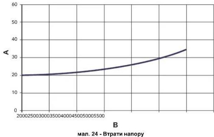
AM6ap
B Bntpatn I/roD
5.3 Ta6nua texHiuHx daHx
PECYPCPA60TbIMCPOKCLJXKbbl
CpOK CnyKb3aBnCt OT yCNOB N EKnpyatauN, YCTAHOBKN TExHnueckoro O6cnykBaHn.
yCTaHObKa 06OpYIOBaHnI DOnJHn IpnO3BODNTbC8 B COOTBETCTBn C DeNCTBYOUIM 3aKoHOJaTeNbCTBOM,a H3NaHbIAOUIneCe DeTaN IOnJHbI 6bITb CBOEBpeMeHHO 3aMEHeHbl.
PeeHnO npeKaueHnn EKNNyataaun, cncaHn yTINN3aun npHHMaet BnaJeue uXoDAu N 0aKTNueckoro COcToHnOBOpDouBAnuN 3atpat Ha peMOHT.
CpOK cnyK6bl-10 nT.
3aBocKa Ta6nUka HaxoDntca Ha 3aDHei CToPoHe KoTna.
Ybaxaemblnokynatelb,
Bnaoradapn Bac 3a To, YTO Bbl Bbipann KOTen FERROLI, Hmeoun camyo CbopeMeHHyko KOHCTpyKUIMHO, BblONHHeHHbI NO nepeDobm TExHOJIOHM OTNmuOuNCBaBcOKoHaDEKHOCTbIO HAeCTbOM. IpcmBAC BHNMaTeNbHO npOHTATb HactOJIeE pyKOBOCTBO, T.K.B HEMnpOBIOrCA BaxHbIe yka3AHnno 6BeOnaCHOCTnYCTaHOBNk, 3KcNpyataUN IN TEXHmueckofo O6ClyKmbAHR arperata.
PEGASUS D Koten npedctabnreT cobO tennoBo rehepatop nI OtonneHn IBC (onu), KOTOPOM Moryt 6bIt NcnoB3oABH JxndKOtonnBBH Binr Raobie ropeonouhye cTpoNCTBa C noDyBom. Kopnyc KOtna coOpah n3 yuryhnhx anEMeTOB, COeHNHeHHbx MeKdy cOB0d BeyXHOCHBMn KObnAamn CTkAnBMn BOttAmn n3 CTanl. KOHTPOnb u npaBnHEe KOITNOm oBeceNeHBAET MInkponpoecccp C ndpObIMn INTepefcom, npoeocTabnIOU mnpodBle FHKnn peryIpnoBaHn TEMNPepATpyb.

Koten Moket pa60TaB B KOMbHaauu C BHeuHMM 6oJIepom (Onua) dnnr B.C. ONcaHHbIe B HactoIeM pykoBOdCTBe yHKun, OTHocAneCk N pOsn3BOcTBy BObl DnI rFBC, nCNOJb3yOTc TOnbKO npn HaHNN DonONHHTelbHorO 6oJIepa, noKnIOUeHHOMy K OTny, KaK yka3HO B SEZ.3.3
2.2 NaHemb ynpabneHn
pnc.1-PaHEnbynpaBneHn
IereHda
1= Knabuwa -
2= Knabwua+
3 = Knabuwa yMeHbWeHHa TeMnepaTpyb BOdb B CnCTeMe OTONHeHH
4= KnaBnua yBeHnueHHa TEmnepaTpyb BOdb B CnCTeMe OTONHeHH
5= Dnncnnen
6= Knabura bibopa pexmna "NeTo / 3mna"
7= He nncnonb3yetc
8= KnaBnua c6poca
9= Knabuwa BKNIOueHn/ BBkIOueHn annapata
10= KnaBnua meHIO "IbaHauoJra TemnepaTpya"
16 = TemnepaIpa, n3mepraemBHeuHMM DaTtHKOM (pHn HAnuHn OINHOHHOR BHeHrero DaTtKKA)
17= BbCBeHbAeTc npn noKluHoeHHBHeHero daTtHKa Hn yctpoCTBa Dy c TaIMepom (onu)
18 = Temepatypa okpykaoueien cpebly (npn hainuun oniounho yctpoactba Dy c tmepeom)
19= INHnkaauna pa6oTbI ropEnK
20= INdkaaIpa6oTbI cncTeMbI 3auNTbI OT 3aMeP3AHN
21= Hndkaunna daBJeHH BObbl CnCTMe OTONNEH
22= INHdkauH HeHcnpaBHOCTN
23= 3aHHe / TempepaTpaB NoaHouem KOHType CnCTEmbI OTnJIeHn
24= CMMBOJ OTONJIeHnI
25= INHdkaunpa60tbcNCTEmbOTONJIHeH
26 = INHUNKIAJIO DOCTHXENHA 3aHaHHoT EmNepaTyPbI B NoaIoUeM KOHType CNTEMBtOgTNHEnE
27= HnDnKaun "JntHnn peKnM
2.3 BkIIOUeHne N BbIKIOUeHne
OTcyTCTBnE 3JNEKTPoNTaHnKoTla
pnc.2-OTcyTCTBne 3NEKTPoNTaHHa KOTna

PnOTKIOUHENKOTJaOTcETN3EKNTPONITHARN/UNNOTrA30BOMmarCTpannCNTEMA3aUHTbOT3AMEP3AHNAHEpa6Otae.BoBpEMdNtIeBHOHEnCNOPL3OBAHNAKOTJaB3MNHNpeNOD,BOIN66ExAHNeupe6aOT B3OMXHOHO3Ame3AHNAPEKOMEHJyETCReCnTBJBCHOBYNEKOTAJIINJXEdo6abNTB CNTTEMAYHTn4PHN,OTBueaUIOY Tpe6oBAHmSEZ.3.3.
Bknouehne kOtna
OTKPOITeOTCEHbIE KnanaHbI TOnnBa.
Bknoute 3neKtponntaHne annapata.
pnc.3-BknoeHne kotna
B TeueHHe CnEduux 120 cekyHa Ha DCNnee BbCEBHeBaTc CmBOJ FH, 06o3Haauoiu uKnCnyCKa BO3dyxa n3 CNCTeMbI OTonneHnR.
B TeueHHe 5 cekyHn Da nCiepee 6 dyet BbCbeHbabTcBepcna nporpamMHO B6ceHcEHHa, YCTAHOBHeHHo B 3NEKTOPHOHN 6Noke.
Pocne toro, KAK CMMBOF HNCHe3aetC DHCINNEKOTONTOBKA TOMATNHCKOMY BKNHOHENIO npk KaKDM 3a6ope BOdbI TBC Nnnpnoctynnnm KOMAHDbI OT KOMHATHORO TEPMOCTATA.
BbIKIOueHne KOTna
Haxmte knabmy on/off (no3.9-pnc.1) B Teeyne 1 ckyndbl.
pnc.4-BbiknHoueHne KOtna
Korda KOTeB BIKIOHcH,Ha 3JNEKTPOHHbI 6NOK npoDOnKaET noDaBaTbcra 3NeKTPuueCKoe NITAHme.
CnCTema OTonneHn He pa6oTaET. OCTaETcA kTbHOI CNCTema 3aunTbO T 3amep3AHn.
Длг NOВТOPHOROBKIOUChENKOTNa ChOBA HAXMITE KnaBnWy on/off (no3.9 pnc.1)ВTeueHHe 1 cekHybl.
pnc.5
TenebpKOTen rTOB K aTOMaTHueckomy BkIIOHeHIO npn KaXdOm 3abope ropae HBOdi NIN NO OCTynIIeHN KOMAHDbI OT KOMHaTHOro TepMOCTata.
IpoJIOJIKHTeJIbHOe OTKnIouHeHne KOTna
YTO6bI BbIKIOHTb KOTeJI:
HaxMMTe KhoNkY BKN/Bblk (9-pnc.1)
3akpoTe raObBn BEHTnB, yCTaHOBHeHHn nepeKOTJOM.
OTKIOHTE TOK OT arperata.

B Cnyae npoDOnKHTenbHoro nepepbBa B paOBe T 3nMnHe nepnoDb,HTob6i n36ExKaTb ONeDEHnRApeKOMeHdyETc CNtB BC0 BoY N3 KOTNa;N3 KOHYtpa TBC N OTONHeHn. Hn cInTB BOy ToNbKO N3 CTeMeBb TBC N 3aNTb COOTBcTCTByOooe CpeCDTo B pOtnHB OneDEHnHa (AHTnPpN3) B OTONbHbN KOHTyp, COrnaCHO npedncaHnM N3 SEZ.3.3.
2.4 Perynipobkn
IpeeknoueHnepeXmOB"Teo"/"3Ma"
HaxmTe KnaBnU JTeO/3nMa (no.6-puc.1) Ha 1 cekyHdy.
PNC.6
Ha dncnnee BbceBuaeTc CmBON "IeTo" (no3.27 - pnc.1).Pnp 3om KOteN 6ydet Bbpaabatb ToJbKO body nra TBC.OctaTcA kAtNBHO cnCTema 3aunntbOT aMeP3AHH.
IINBbIKIOeHnpeXIMa"NTo"BHOBB HAXMNTe KnaBnHy NTo/3Ma(No3.6-pnc.1)Ha 1 CKeKyH.N
Perynpobka TemnepaTybI BODI B CNTEme OTonJIeHn
TemnepaTpaB CnCTeMe OTonHEnHpeynpyETcB npeDax O T 30°C Do 80°C c nomoubKnaBIM (TeT.3u4-)pnc.1.
OHaKo He peKoMeHdyetc3 KcNlyaTnpoBaTb KOTe npTemnepaType Hxke 45°C.
PNC.7
PerynpoBkA TeMnepatpyb B CnCTeMe ropyeo BodochaKeHnra (TBC)
Temnepatypa Bcnme TBC perynpyerca B npedenax ot 10°C do 65°C c nOMOBIO KNAHNI (no3.1n2-pmc.1).
PNC.8
Perynpobka Temnepatpyb BO3dyxa B NOMeueHHN (C NOMOuHO ONHNOHOro Tepmoctata Temnepatpyb B NOMeueHHN).
3aJaaie C noomoiIb TepoMCTATA TernepaTpyb BO3Dyxa B NOmeuHn HxHyIO Tempepatpy BHTPN NOMEHN. PIn OTCYCTBn TepMOCTATA TernepaTpyb BO3Dyxa B NOMeHn KOTEN oBeCNueHbAet nobpeKahne B CNTSEME OTONNEHn 3adaHNO TernepaTpyb BObl.
Perynpobka TeMnepatypbI BO3dyxa B NOMeueHNN (C NOMOUsBO ONUHOHOrO yCTPOHCTBa DcTainepom)
3aadaTe c nOmoIbIO yCTPOIcTB A DY c TaHMePOM HkyHyo TEMnepatpy BHTPN NOMEeHN. KOTen 6yTeT NOpeKINbA Tbe TMnePepatpy BOnB b CNTcEMe, Heo6xOmyo DnA obSeCNEHnA B NOMEeHN aAaHON ToMepatpyBo 03dyxa. B TOM, YTO KaCaetc pAObTo kOTNa CytpoNCTCBY C TA HApemOp.CM.COOTBETCTBYKOuHOHtCPyUHO HA 3TO yCTPOCTBO.
Плаваюцая Temnéратура
PnycTahOBke BHeHrero datuHa dncnnne naenennynpaBHeHH (no3.5-) BBBOITcpcn.1TeKUaB HBeHHra TemepaTyPA, hmepeRMA 3TM daTHNKOM.PnI 30m CNTeMaY npabEHHN KOTJ mpaOaET B pEXMHe "IInabaKoAa TEmepaTyPA.3OTm peXHMe TEMEPaTyBa B CTME OTOPNHEA perynpetyTC B 3ABNCMOCTN OT BHeHHxKN HImMaTueCcknx YcNOBn C TEM, YTObI o6ecNeHTb MAkCMaJIbHbIK KompOpT IN KOHOHMO HEPINB TteHEHBCrOra BD.YacCTHOCTn, npYBEHNHEHH TEMepaTyPi HApXHOro Bo3dyka yMeHbSAeTc TEMpePApy NOdaBAeMoB B CTeMcy OTONNEH BOI B COOTBTCTBN cOnpeDENEH "XapAKTEPCTKIOKOMNEHCaUN".
B pexnme nnaabaioe temnepatypb belenuHna, 3aadHaHc n omoohy knaabH peryunpoBKn OTONENH (no3.3 H -PcH.1) , ctaOBHTCMAKmcmansHo TEMpeNPATpyo BODby CNTembl OTONENH. PekomEnHyTeC yCTahAbNnBaTb ee Ha MAcKmamhHyO beleniuHny, YTOb6No3BOINMb CTENEM BbIOnnHrPB eYERPNOPKY BO BCEM NOJIeHOM paoochm dhanaa3OHe.
PeynnpBKn KOTna DOnXHb 6bTb BbNHeHb npn erO yCTaHOBe KAnuHpOBaHNm CneuaHnCTAmn. B DaJIbHeHwem NoIb3oBaTeB MoKet Cam N3MeHTB IN Dn IObeCENeHMaKcMmaHbHorO Komfopta.
KomneHcaunOHnKa KpNBa n CMeueHHe KpNBbIX
PnO OHNKpAHTOM HAKATN HA KAnBnUpy Pekm (no3.10 - pnc.1) OTo6paKaTeC T aKtTnecka KOMnEcauOnHna KpBaa (pnc.9), KOtopyo MoXHO N3MeHntb C nOMOuIbO KAnBnU cnCTeMb I BC (no3.1n2 - pnc.1).
N3MeHHTe KOHpyrauKpBBoB B npdeJax ot 1 do 10 ckyH B 3aBcMocTn OT xapakTePcTn (pnc.11).
Pn yctahOBKe KpBbON Ha 0 pexm "nnaBaIOuei TemnepaTypbI" OTKnIOuAeTcA.
PNC.9-Kpnbar noro03aBncmoro perynpoBaHn
PnnaHakattn KnaBn peryNpoBk TemepatpybToOnTneHn (no3. 3 n 4 -pnc.1) oecneHnBaTeC Doctyn K peKHM npapannenbHoro mmeHHe HnKpBx (pnc.12), mHEHemRo C nOMOuBKn BnAaHcCTeMb TBC (no3. 1 n 2 -pnc.1).
pnc.10 -PapannenbHoe H3MeHeHne KPNBbIX
PnnoBTOHOM Haxatnn KnaBnM PeKMM (no3.10-pnc.1)ocyueCTBnEeTcBbXoD n3 peKIMa peryNupOBKn npanneNBkxPbBix.
EcHn TemnepaTpya B nomeseHHN OKa3bBaetc Hnke XeNaemO, peKoMeHnyETcBb6pTaB KPNBHyIO 60nee BbICOKOrO NopraKa, n HaobOpOT. DeNCTByITE, yBENHvBaI INy mEHeIha Na Ody H eINHcy I OueHMba , kAKIM O6pa3OM 3TO cKaKeTcR TemnepaTyB NOMeEHNI.
pnc.11-KomneHcaunOHhIe xapakTepeNCTKn
pnc.12- PnpMep npaannenbHoro CmeueHHN KPNBbIX noroDo3aBnCMORO perynpoBaHHN
Perynpobahne c ndctanchoHHoro nybta ynpablenra c TaMepor

Ecnn K Kotny nocknoeHc yctpoCTBO nctaHnOHoro ynpabneHn C TaImepeom (Ocnma), Bblieonncahhbe perynpoBkn npOn3bOraTc B COOTBETCBN c kya3AHnMM, npBeHeHHBM Ta5nla1. PnE tOM Ha DnCnnee nybTa ynpabneHn (no3.5 -PNC. 1) BbcBceHnBaTe Tc Tempepaty a NOMEuHn, n3MepeMaY cypoCTOBm nctaHnOHHO npabneHn.
Ta6nua.1
| PeyrnoBokA TempepaTpybI BOJI B CNTME OTONJIENHIA | PeyrnoBokA MOKHO OCUJICTBILITK KAC C PUYTA DMCHTAUHNOHORO ypanabheni C Taimeporom. TAK H C PUYTA ypanabheni KOTOM. |
| PeyrnoBokA TempepaTpyb I CCTME ROPHRIO BOOCHABJHNNI (TBC) | PeyrnoBokA MOKHO OCUJICTBILITK KAC C PUYTA DMCHTAUHNOHORO ypanabheni C Taimeporom. TAK H C PUYTA ypanabheni KOTOM. |
| IpekHNoHene pexmMoB "JTeo"/ "3HMA" | Pekim "JTeo" obNadaet prNPOHPETOM HAD KOMAHIDH BA KIQUHene otOnJIENHIA, KOTOPAR MOKOT NocTyHNTB OTo NUY Tc Taimeporom. |
| BbIobpeKHMOB ECO/MONTF | Pryb bIKHnOHEnHH PEXIMHA TBC C PUYTA DY KOTEN nepeXOJITB P BXMM "Eco- nomy". B 3THX yCNOBHX KnabuHsA 7PcK. 1 - Ha panEHNI KOTIN 3KTNUHHe. Pryb bIKHnOHEnHH PEXIMHA TBC C YCPTPOCTBA DY C Taimeporom KOTEN yctANAHIMBaTcB A PEXIM COMFT. B 3THX yCNOBHX c NOMOUsb KIaBHIM 7PcK. 1 - Ha panEHNI ypanabheni KOTIN MOKHO Bb6pTa NbIOB K3 3THX dByx peKHMOB. |
| IplabaOuHaa TempepaTpya | PeyrnoBokA MOKHO PPAHIOUH TempepaTpybI MOKHO PINOKBOOHTB KAK c PUYTA DMCHTAUHNOHOrO ypanabheni. TAK H C NOMOUsb 3NEKTOPHHO 6BnKa ypanabheni KOTOM: PIPROPHTOM oBScadaet peryrnoBokHene B PEIXM PPLABAOUH TeMnepeTpybI, BInPOTNHEMOE 3NEKTOPHHMI 6BnKOM KOTTRA. |
PerynpoBaHne daBHeHH BODbI CnCTeMe OTonJeHH
DabneHnnoNTKn npn xonodHn CnCTMe, KOHTpOInpyEmoe no noka3AHIO dncnner, DOnKHO COCTaBnTb NpIMePHo 1,6ap. EcnN BO BpMa paBo TB daBHeHne BOyB CnCTMe ynano DoBENHHb HNKe MmMnMbHb DOynCTmO, TO 3JKeKTOPhBBM 6IokOM ynpabHnne KOTNM BBIOIDTCKa KOH HeCNpABHOCTn F37 (PcN.13).
pnc.13-HeoctatoHoe daBneHne BOdb BCnCTeMe OTONNEHn

Tocne BOCTAHOBENHn DABNEHn B CHCTeME npOCXoDnT ABTOMaTHNeCKOE BKIOHHeMn CnKna Cnycka Bo3dyxa (120 ckyH), npHem Ha dnCnnee BBcIEBNAeTcR CmBON FH.
3. YCTAHOBKA
3.1 Yukazamaо obuero xapaktepa
YCTAHOBKA HACTPOKIA FOPEJIKN IONJKHACOUYECTBTRTCOTIbKO CNEUANIM3NPOBAHHbIM INPECOHAJOM, IMEIOJIM INPOBEPEHHVKO KBAMINKALHIO,IPN CO5NIDEHNIPNBEEHEHbIX B HACTOJEMTEXHHCECKOM PYKOBODCTBE YKA3AHN, INPEINCAHN DEICTBYIOJERO 3AKOHODATEJBCTBA, NIOJIOKEHMECHbIX HOPM IN PABUN, IN B COOTBETCTBM C INPHRTBM IEXHHUECKMN TPEBOAHNMR.
3.2 Mecto yCTaHOBKM
Koten donken 6b1b yctahobnB CneunabHo OTbeHHom d30tien cenn nomeeHHM, MmeoHoue 0BETpcn7, ocechuehbaouie DocatoTHyBEHTNIAHc B COOTBCTBNC DcetbyuHMM HOPaMM. EcnB aDHOM nomeeHN yctahOBHeI hKetoTOpBIE rOepKN HIN BYTJHKHe BENTNlAToPb, paOtaUOine OHOHBpeMeHHo, To BEHTNIAUOHHe bOTepn TOnkHNb IMMeTpBa3mEpb, ocechuehbaouie OHOHBpeMeHHypo sbObyE cxn annapatOB. B NOMeHN, B KOTOPM yctahobnE arperat He donkHb haxoDntbc ORteONaChBe npeMeTb> Nm MATEpHaIb, eKeine Ra3b, bInb HpyTeNeTyHuBEeCTBa, BCAcbBaHne KOTOpBX BEHTNlAToPOM MoXeT npReCTNu K zarpa3HeHIO BHytpEHnK KHANOB rOepKN HIN rPONoOHOr RONOBKN. NomseHene DonkHoo 6b1b cyximn He noDBepratbc Bo3dJeCTBO DOxJr, CHERa IIN MOPO3a.

ECn arperat yctanaaBaaetc rcpen Me6eHN HIN 6OKOM K cTeHE, CneDyET npdycmotptb CboAoHnoepoCtpaHCTBO, Heo6xoHmOe dA demOnTaKa KOxyxu H bblONHHN O6bHbHx paoT0 NoTex6CnyKBAAHIO.
3.3IpaBnueckne coeHHeHHa
NapametpbT tennoBo MOUHCTNO KOTnAoJXHbBbIbOnpeJeHbI 3apaHee nyTe m paceta Notpe6HCTNo B Tennne B NoomeHmB COoTBcTBBN CDeCTByouOmm HnpMaBAMn. Dnla ObceNeHNO npaBnHOro N HAdEHO HorO FyHKUHOHNPOBaHn Annapara TndpaBnueckar CNTema DoONKHa 6bbl OChAeHa BCMeM Heo6XoDMbIMbn Ia3ToTt ceNzIeMeHTAmn. MeKdy KOTlOM nCCTEMO OTOnPENHE PekOMeHdYcETcAHOBbTOCeNbIe KNaHbI, NO3BOJIOuHne 3IOJIPOBbT KOETnOT CTMeHbC BYCnuhe Heo6XoDMcOns.

CnBHOe OTBepCTHe npdoxpanHntbHoro KnaHa DoJNHO 6bIb CoeHNHO C BOPOHK IN C KANAMINAOHHOITpy60B NO36EkanHE IpOIMBa BObI Ha NON B CNYae Cpa6aTbBAHn KnaHa PnnppeBbIeHN DABJIeHN B OTOInTebHO CHCTEM.B npoTHBOM Cnyae H3ROTOBHTb KOIa He HecET HIKAKO8OTBTCTBEHNOCT3a3aTOnnNEHn NOMeueHn npn CpabTaBHAn npdoxpanHntbHoro KnaHa.
HcnoNb3yTe Tpy6blrpaBnueckOCHCTeMbI Dnra 3a3eMNEHH 3neKTPnueeckHX np6Op
Ipepe yctahOBKO tuaTeBHO npOMoTBE BCE TpybCnCTeMbI Jra ydaJIeHNI OCTaOHTbIX 3aRp3HIOUxN BeueCTB INN NOCTOPOHNX Ten, MOryux NOMEuATb npabINbHO paBoTe annapata.
BbINOHNHTE NOKIOHHe Tpy6 K COOTBETCTBYIOUMM WTyuepam, KaK NOKa3HO Ha cap.5.I n cornacCHO CMBOJAM, HMeIOUIMCRA HA CAMOM arperate.
XapakTepeNTKBOBdI DnCCTEmbOtonneHn
B CNYaee,ecnJXeKCTKObT B0dbI npBbUaet 25° Fr (1°F = 10 nnn CaCO3), HcnoJb3yemaB Oda DOnkha BbIb HaNDeNkaaMmOBpa3oM NOrTOBHeA, YO6bI npDeToBaAsTpBcbpOzBaHne HAKNNHa KOtNe. NocJe NOrTOBKn KcEeKTCKoB B0dI He DOnkha BbIb HNXe 15° F (DII 236/88 o NOrTOBKe B0dy, npEHa3HaYeHHo Jn Da neOpBeckoroNoTpebHeNHa).BoDOnIOrTOBKa OBaTeBHaE, eONc SiCTema IMeET 60bnYu npOTaeXHeHOCT bIN pNPI qACTOM BbInONHeHN NODNIKN CNTeMbI.

EcnB TOOe NOBOda XONODHO B0bI yCTaHABINBaETcY cTPOCTBO YMRAHENHA,OBpaNTME BHIMAHNE HA TO,TO6bI HE CNIWOKM MHO CHN3NTb JXCTKOCt BObHa. Hc Camo DeJe 3O MoKET pNBecTe K PpEXDeBPeMeHHOMy UxyDueHIO CBOCT MBaHHeBOrAOAHOa BoInepa.
CnCTema 3aunTbO T3amep3aHn,KnKne aHTnΦpnsbl,do6abkn HnHn5ntopbl
KotenobopyoBaan CNTeMoN 3aunTbI OT nepeMeep3AHH, KOtoper B KNIIOyaeEero B pexmne OTOENHnB CnYae, KOrda TemnpatypaBoDbl, NOdabemO B OTOINENTbHyO CTcEmy,OnyckaTeCn Hxke 6"C.3Ta CNTeMa TcKIOHuaTeCpnn PONKIOHeyen KOTNa OT CNTeMb 3NEKTPOINTHAnu NNNr Ra3OBM MaNCTPANl. NcNObSBOAHNe XnKHXn AHTnFpIn3OB,doabok INHNbINTOpOB,paseWaeTCB CNYae HeoBXODMOCmTOnbKO INKNOHTeBHO,ecnNX INRTOBITBe DaET rapaHTNo,NOITBepkDaOHUyO,TOERO npOyukn OTBeaye TaHOMBY NNDcIOB3oAHnHnHE nPnHnHnBTpeA TEPNOOBMeHHNK KOTNa n DpyTN MOKNKeTKyOuImn H/INn MATEpaNAm, IcNOJ3oBAHbIM B KOHCTpyKUnn KOTNa n CNTeMb1 3anpeaaetcN cNOJ3oBaT bXkNDcTn-AHTNp3BIs,doabKn INHbINTOpB, cHeuMaJIbHO He npDeHaHaEHHbIe JPNIMeHHN B TEPNOBbix yctAHOBkXn HecOBMeCTmblc MeATepnAAMn, IcNOJ3oBAHbIMN BOKCTPKUKN KOTNa n CNTeMbIe
CoeHHeHc6oJIepomnIgBC
3neKtpoHnnaTnnapata npedha3NaHeHa TaKke nnypabHeHn B HeuHm 60nepom nnpO3BcTB BoDy fBC.CoEHHHeHn Tpy6 CnCTeMBo OTONHEHn I FBC DoJNbHb6blt BbIOnHeHb B COOTBeTcBnco cxemoy pnc.14 (hacocbi n 60pahtbe KnaanbH NoctaBnhotCOTdJeBHO).BbONNHTE: 3neKtpnHeckme coeHHHeHn B COOTBeCTBnco cxemoy cap.5.4.NcOnnb3yte DaTtHK FERROLI.Ppn cNeDyUoCEMK BkIOuHeHHArperata CnCTeMa ynpaBHeHn OOn3Haet DaTtHK 60Inepa n ABOMATuHECKn HactPnBaTeCn Ha paOToY C Hm, Bbl3BaAakTNBaCuHIO DnCnner n ycTpoBcY npapBHeHn, Heo6xoDnMbIe nn PaObToBpeXnme fBC.
pnc.14-Cxema coeHHeHH C BHeHm6oHnePOM
JereHda
8 BbIXoHoiWtUepeKoHTypaTBC
9 BxoHnWtUep KOHTypa BC
10 BbIXoHOH uTyuep KOHTya oToJIeHHa
11 06paTHbI Tpy6oPBOD CnCTeMbI OTOpHn
3.4 PpncoeHHenne Kra3onpoBovdy
IpeXeJeYm npCTynatb K NOkKIOUeHIO KOITNa K CnCTeme RaOChA6KeHnna, yOCTOBepBtEc, YTO KOTEN pIeHNa3HauyeH dNn paBOtBu IMeHNO Ha DAHOM BInTe TOnINBa N TuaTeBNo IPOnCHTHe BCE rA3oBbtepybSdy nA yDanaEHnN NOCTOPOHNNBeueCTB, MORYxu NMOeMaTb npABINbHOpaBOte arperata.
TnoknnoaetcK COOTBeCTByuOeMy naTy6Ky (cm. pnc. 25) c co6nHOeHneM
deNCTBHyoXn HOPm, C nCNOIb3OBaHMe JxctKMO metJInHecko TpybI INn H6KO
7nHaRa n3 HepKABeOJeC tAnn Co cnnNoHoi OnNetKo. Mekyra3OpBOOMn
KOTnOM dOnKeH 6bIb yctAHOBEn RaObbl KpaH. PpOBpe TepMeTHHOCTb Bcex
ra3OBbIX CoedHHenH.
Pponyckna cnocobnctb cuetnka r3a dojNkha o6ceueHBt bOHOBpeMeHHy0 paOby Bcex noknioueHbIX K Hemy arperatob Dnametp ra3oBOrO natpy6ka, KOtopbI bIxOanIT NKTOnA, He RAJIETc ONpeDJeIOUm pnp BblOpoe DnAmetpa Tpy6bl, COeINHIOUeKOTEN IN CHTIK; DnAmETp ONpeDJeTcCnAcho DeECTBYQUIM HOPMn 3ABiCNPT OT dInHb Tpy6bl Notepe JBADNEHBA HE.

3anpeaaetc HcnoJb30BaTb ra3ObIe Tpy6oPBOBbl B KaHeCTBe npBOoDnKOB CNTEmbl 3a3EMnEner 3JeKTPoo6OpyDobAHN.
3.5 3neKtpnueckne coeHnHeHn
IopKluoyehne K cetn 3neKtponntaHn

3neKtpnckcA 6e09aHc0ctb annapata o6ceNcHbaeTc TaBko npn eropnabnblHom NpokHCHM K KOHTy 3a3eMENH, OTBHeauOme TypeoBaHmR MEChTyBouHx HOpm TexHHKu 6e09aHc0ctH. 3fKePcTbHocCTb KOHTpy 3a3eMEnHn ERO COOTBeTCTBE HOPMAM DOnKTHb 6bTb npoBepeHb KaanFmuPOBAHbHM nepcohanOM. IVrTOBtENTb He Hecet HNKaOK OITbETCBEHOCHT 3a yueep, MoryuHb 6bTb pnuHHeHHM OTCYCTBcEM 3a3eMENHn APERATA. YIOCTOBepTeCb TAKKE, YTO CNTema 3neKtponTahnn COOTBeTCTByet MAkCMAHBOH nOtpeBnREMO MUoHcHOr aERpATA, Yka3aHHHO HA TablMHKc HOMHaJIbHbIX DaHHbIX.
BHytpnHHe 3neKtpnueckme CoepnHHe H BKTne yke BblonHeHb OH cah6xekn TaKc ceTeBbIM hUypom TnHa "Y" Se3 BNkN. PNOKnIOHHe N Cetn DNOJHO K bTb NOCTOBHbIM, pNHEmMeDy MecTo NpOKnIOHHe K cETn KOTNI CNEyET YcTAHOBT BdyNXONIOCHb PA3MbKaTEb CpaCtOHeM MeKdy Pao3OMKHTbHM KONTAKTM He MEHee 3 MM, a TAKe npDeoXPAHITEN MAKc.HOMHNAM 3A.PnP NOKnIOHem K cETn BaxHOE HAChEnMe IMeT co6NIOHeH NoIpyHOCTn (pa3a: KOPINHEBII npOBd / HEHTPANb; CHHN npOBd / 3EMJI: XeNTO-3eNEHbI npOBd).PnMOtAnke HnZAMHe e CeTeBO rHypa 3eMNHOH npOBd DOnKeH 6bTb BInNoTHe Ha 2 CMnnHHee octanBbIX.

Cetebo shyp arperata He noDneKHT 3aMeHE cAMM NOIb3OBaTeHem. B cnyae NopekdeHncaTeBc0eToO shpA bIKNHOHTe arperat; o6paauTecB nraero 3aMeHb NCKIOHTeHbKO KBAHNPHUPOBAHBM CNEuMaNTCTAM. B cnyae 3aMeHb ceteboro shypa HNCONb3yHe NCKIOHTeHb KOABen TnPA "HAR H05 VV-F" 3x0,75 MM2 c MAXcIMANbHM BHEUHMM DnAmETPOM 8 MM.
TePMoCTaKOMHaTHoN TeMnepaTpby (onu)

BHIMAHHE: TEPMOCTAT KOMHATHOH TEMNEPATYPbI DOJIXEH BbItb YCTPOUICTBOM C KOHTAKTAMH HE NOI HANIPXJEHNEM. IPIN NODAUE HANIPXJEHN230 B HA KJIEMMBI TEPMOCTATA KOMHATHOH TEMPEPATYPbI NOBIEHET 3A COSOH HENODJIEXKAUEE PEMOHTY NOBPEXJEHNE 3JIJKTOHHIITAbI.
Pn noKKnHouEHm peryIaTOPOB KOMHaTHOH TemnepaTybC nobpeMeHHo nporpAMMOy npAbeHNEHn IaTMEPA, he CneJeYeT 3aNbITbBaTbNx cyepe3 paMbKaIOUHe KOHTaBt. B 3aBNCMOCNT O Tnna YcTpoCTBA NHTaHHe DOnKeH NODBoNTBCs HApMyO TO cTei HN OTo GataapeK.
DocynK6nOKy3aXMMOB
OTBHTNTe 06a BHTA "A", pacnoIoxeHHbIX B BepxHe yactn naneHyn npabneHn m DEMOHTNpyTE KpILKy.
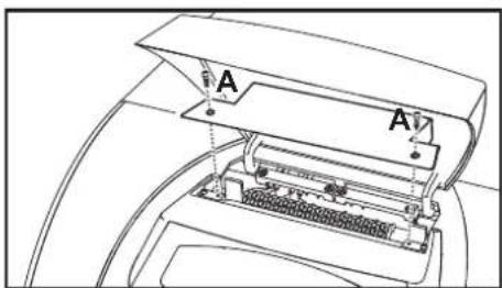
pnc.15-DocTyK KJIeMMHOn KOPO6Ke KOTna
3.6 NpoknoueHne KOTNa KdbIMoOTbOy
Tpy6a noCoeHHeHHK DbIMoxOy DOxHn HMeTp He MeHbIu Yem dAmapeo CoDInHbOno HapTy6ka Ha npepbBatene TaR. Iocne npepbBatene TaR dONKeH nHTn BeptKaIbHbY uactok DbIMoxOa DnHoi He Mehee 0,5 Metpa. Pa3meBn MoHTaX DbIMoxOob N Tpy6bln NoCoeHHeHHK K HmKOTna DoJIHHkCOOTBcTcBOBaTb DeNCTByOuMn HOPMAM.
HnAmEt npatpyka npepbBateTn Tn NOKa3aH B pnc.23.
4. YXOD IN TEXHNU ECKOE OBCNJYKUBAHNE
4.1 PerynipobKn
Bce onepaunm perynnpoBaHnna n nepehanadkn KOTNa DoJIKHb BbINOHHTbcra KBaIIMpOBAHHbIM nepcoHAnOM.
NtOToBHTbKoTNa CHeMaTc C c6eB BcRkyo OTeBTCTBeHNOCTb 3a BpeD, npnHHeHHbI NIOJdM u/nnmUyIeCTBy, B pe3yIbTaE HeCAHKIOHPOBaHHOTn H3MeHEHn KOHCTpykIm arperata HEBAHNIFLIOBABHbIM n HeyONHOMOHEHbIM NepCOHAnom.
AKTINBaunpexma TEST
OHOOBPemEHHO HAXMITE KNAHINCHCTEMBI OTONNEHNI (no3.3n4-pVC.1)BTEUHEH5 CEkyHdIaIKTBAUAPENKIMMAE TEST.KoTe BKNHQHTCRA HAKMCMANBOH MOUHOCT, 3aADHOHAK,YKyA3AOH CcneHyOeHm nparapraF
PnO TOM CMBONBcNCTeMb OTONNEHIN (no3.24 - pnc.1) H cNCTeMb IBC (no3.12 - pnc.1) Ha DnCnne HauHHaHT MHRATb.
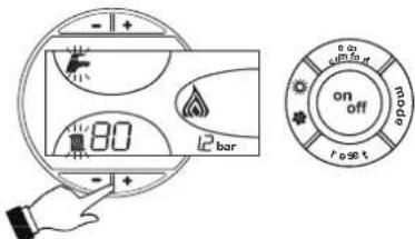
PNC.16-PexKIM TEST
IyBbIXOdaH3peKIMMA TEST NOBTOPHTNOCNEOBATENBHOCTAOKTHBAUIN.
B NIO6OM CnyuapepeKIM TEST ABTOMATueeCKN OTKNIOHTbCyepe315 MNHT.
PerynpoBka MoUHOCTH CNTeMbI OTONJIeHNIA
Ha KOTne PEGASUS D MOKHO perynipoBAtb TennnoByo npOn3BOJTeBHOCTb TONK IN, CNODBATEHNO, TENNOYIO MOUHOCTb, NpeDABAEMyO Bode CUICTeMb OTONNEHINr, 3TO DEAETCA MCKHIOHTBHO NYTEM perynpoBKOHOCHOBH O ROPENKc NOMOscuBa rAOBOrBEHTNl (CM. pnc.17). Ha rpaФн<|im_start|>ax, npiBDEHHbX b NaparpaFte 5.2 nOKa3aHo m3MeHHeNepepeDABAEMO Bode TENNOBO MOUHOCTB 3ABUCMOCNTO IN3MeHEnHp a60eero dABHEHRAPORENIKI BO3MOXHOCTb pNpBeHnna MOUHOCTKOTNA B COOTBCTBNE C pealNBHMn NOTpEHOCTMn OTONNEHINr O3HAuET, nPekDe BCERO, CHNKHeHne NTOpEBu NKOHOMN TOTONIBa. Kpome toro, npN perynIOBKe MOUHOCTn, perMaMMTHPOBAHNN TaKke CTaHApTOM, KOTNBc coxPAHROT 3HAHENr KPIN X npakAPTEPCNTMKICROPAHNR NOIT 6e3 IMMEHNH.
Perynpobka BbInonHnraTeC npn pa6oTaOeM KOTne n npn yCTaHOBmEeCA TemepaType BObl B 60inpe.
- C nOMOJIbHO He6oJIbIooI OTBepTKI CHIMMITE 3aIHTbI KONNAK 5 BTOPMHORO npIBOda ra3OBOro BEHTINrIPOc.17.
2.ПадкнчITE Мановет PMKКЕМДавьгеля 2(PNC.17),pacnoJoxeHHORO NOCE rA3OBORB BENTNIA,3ATMENPEBEIDNTpyKTEPMOCTATA KOTJNA HAKMCMYM. - Perynipnye daNebnene c nomoubilo bHNTa 6 (pnc.17) ha Jenaemaoe 3aHene, pykoBodctByoC hndarpAMMaMn, pnpeBedeHbMn B naparapde cap.5.2.
- I OkOHaHHbIeONHcAHHOIonepaunBkHIOHTeBbIKIOHTe ropeKy 2-3 p3aHepe3 perynpOuouI TepMOCTAT INPOBepTe, COOTBeTCTByET DaBneHne paAee 3aADHOMY 3HAeHnIO; BpoTNOB CNYae HeoXoDMBO bIoNIOHTbONNOHtEBHyOperynpOBYo Tex npO, noka daBHeHne HE doctmHET npBaUNHOro 3HaehnE.
IpehaTpoKaHa npyroTnra3a
Koten nprodeHnpa60bHa nppoHOMrase(G20-G25)HnHa CkXKeHHom rase(G30-G31).
Peximra3dpanpa60tbbblupaTc np3aKa3eN yka3aH kA hynakOBke, TAK H TaBnHKe
HomHnabHbHX daHNbHX arperata. B cnuyae Heo6xOIMOCTn nepebOda KOTna Ha pa60ty c razom, OTNHIMOr 0ra3a, dnn KOTporo OH b6bn Hactpoeh Ha 3aOBe, Heo6xOIMO npno6pcttn
CneuHbNo np eYcmOTpeHHbI Dn 3Toi CEIN KomnNeKT nDn nepeo6OpDobAHn H
DehctBOBtB, KAK Yk3AHO HIXe:
- 3aMeHHTe fOpCyHKO OCHOBHO RopeKIN H NIOHOI ROpeIKN B 3aBHCIMOCTHOT CnOJIb3yEMOro BNDA r3a,pyKOBOCTBycB Ta5mEe TeXHmHeCKHX XapAKTePNCK B cap.5.3.
- CHHIMTE c raoBOrO BEHTnIa MANeHbMn 3auHTHbN KOINaK 3 (pnc.17).C nOmoBIO MAHbKOOnTBePkn perynnpyTe "CTYNEHb" po3xHa Ha OCHOBAMn Bb6paHrO da pabOt Ta3a (G20-G25 NOONKeHne D pnc.17 Hn G30-G31 NOONKeHne E pnc.17); yCTAHOBtHa MeCtO 3auHTHbN KOINaQoK.
- BbINOHNHTe peryINnOBky DabHEnHra3a Ha ropeKe, nCOnb3y 3HaueHm, npBbeHHeB Ta6Piue TeXHHuecknx XapakTePncTK, INa Bb6paHHoro Tna r3aa.
- HakneiTe Tabmuky, BxOaIuyo B CoCTab KOMNKeTA dna nepeobopyoBaHnA, pIOM C TaBnKoTexHnuecknx DaHHbIX dna noTbePcxDHeHn BblonHeHoro nepeobopyoBaHnA.
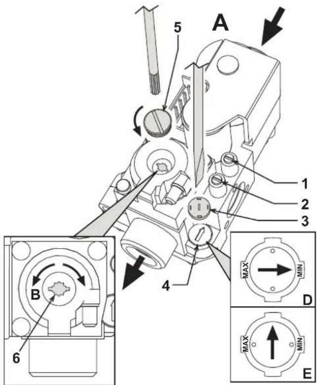
pnc.17-PerynpoBaHne daBnenn
Ta3OBbI KNaHAn
YMeHbWeHne DaBnEHHa
YBeIyueHneIaBHeHn
PerynpOBKa CTyneHn po3Kmra npn nCnoB3oBaHHN PIPPOJHOrO rA3A G20-G25
PerynpobkactyneHPO3Kmra npnncnoB3oBaHHCXXKEHHOFOA3AG30-G31
KoHTpOlbHAR TOUka N3MepeHnRAaBHeHnPAcNtOKeHHa nepeIra0BBIM KJIanaHOM
KoHTpObHaT ToKa N3MepeHn DaBneHn, paCNOJIOKeHHa noCne ra3OBoro KnanaHa
3aunThbKoNnaQok
PerynTop "CTYNEHN"po3kna
3aunTHnpo6ka
BnHT dnperepynpOBKn daBJIeHn
4.2 BbOaB 3KcnnyatauHIO

BbOd KOTnla B 3KcNITyatauHIO DOLJKe H BbINONHTb BbCOKKBaHmNtUPOBAAHbIM NepcoHAnOM. KOHTpONbHBeIonepaHm, KOTOpBE CnEDYET BbONNHTb NpeD NpEBMbIPO3XnRGM,a TAOKE NOCTe PNOBEdHnTExHHHeCKORo O6CJyKbAHBaHn, BO BPema KOTOPORo KOTen 6bln OTcOeMHNeO CTcE NtAHHn INN b6bln pOn3BeDeHb pa60bTaHa npEOdoPAHNTENbHbX yctPOrCTbAX nIN dTeaIAX KOTnla:
IpeBkHoueHHemKoTna
- OTKpoIte 3aIopHbIe KJanaHbI, pacNoIoxEHHbIe MeKdY KOITLOM I ra30-BOIOnpOBoDAMN.
C MAKCHMABHOBO TOPOXHOCTbIO NPOBepTe RPEMeTHUHOCTb CNTCTMBI ra3oCha6xEHN.ДЯOBHApXeHnYTeueK BcoEUNHeHNIXCNOLb3yTeMbIbHbI pACTBOP.
3ANOHNHTBEOONCHCTMYNNOHOCBTOCNCTHTEBO3DXYN3KOTNAIN3CNCTEMBI,OTKpB BbIyNCCKHOKNaNaH KOTJIIE NBaP3NJHbIX MecTAX CNTEMBI OTONNEHNA (ecNI TAKOBBLE IMEIOCTA). - YOCTOBOpBbTeB bOTCYTCTBNIyTEK BObI n3 CNTeMbI OTOPnEHN, KOtypa IBC, IN KOTJI B aPAJIINHbIX COOINHEYNX.
PpOBepbTe npaBnIbHOCTb BblONJIHeHnE JNEKTPnueCKHX COeHNHeHn.
YJDCOTOBepbTecb,TO aRperat npncOeunHeK 3ΦΦeKTHBHO My KOHTpy 33aEMHnHa.
PpOBepeTe OTCyTCTBnE OrHeonacbIX XnKoCTe Nm MaTePnaIOB B HEnocpeDCTBeHHoB 6m30ctN OT KOTna.
Cnyctnte BO3dyx m3 ra3o npobodbix ty6 uepe3 wTyep op 6opa daBneHnra 1 ra30BOro BEHTnna (pnc.17).
BkHouyHe
OTkpOte OTeCHbIe KnaaHbI ToNNBa.
BkIIOUHTe 3NEKTPoNTaHne annapata.
B TeueHne cneDyioux 120 cekHyHa nucnnee BbcBaeuBaetc CMBON FH, oO3Naohouiu cnkyca Bo3dyxa u3 cTcEmbl OTonHeHia.
B TeueHne 5 ckyHn Ha nncnnee 6yET BbcBHeNBbCBAe Bepn nporpaMmHO oecneueHH, yCTAHOBNEHNO B3NeKTPoHOM 6Noke.
Iocne toro, kak cmbon FH nce3aet C dncnner, KOteT roTOB K ABTOMATueckomy BKIOUeHIN npn KaKdOm 3a6ope BoDbl BC mnn KOMaHde OT KOMHaTHoro TepMOCTata.

EcnnnncnnpabnbHoro BblnonHeHHnO nUcaHHbIX bIwe onepaunr ropEnKn Ha 3aJxRyTcA,Ha ducnnee noBraTcC KoD HeNCnPABHOCTN A01,To ndoxxnnte OKoIO 15 cekHyd,3aTeM hXkMITE KhONky RESET. Nocne cbpoca CnCTMa NOBTOPI TcIKP0zKHa. Ecnn ropEnKHa zaxKyTrn nocne BTOPO nnbTK,TO cmOTptb NaparpaP noncka HncnPABHOCTe.

B CNYaee OTKIOUeHnE 3NEKTPoINHTAHNIG KOITNa BO BpEMR erO pa6OtIropeNn Norachyt H ABOTAMuHEeCKn CHOBA 3aXgYrTc nPn BOCCTaHOBNEHn NODaHn 3NEKTPo3HePRn.
KohtpOlbHbIe onepaun, BblIOJIHReMbIe BO BpeMpa60tbl
PpOBepeTe repMeTnHocThb TOnnnBHoro KOHTpa N BoOnpoBOdoB.
PnoBepbTe 3eFfEKeTINBHOCTb FyHKUHOHPOBAHnIaBIMOXOoBO BvpeMa pa60tbl KOTna.
IpoBepbTe, npabnIbHO nH cnpkyIpyeT BOa MeJy KOTLOM IN CNTEmoI OTONHEHIA.
IpoBepbTe pa6Oy CnCTeMbpo3KInra KOTna.DnA 3TOro HeckoNbko pa3 BKnIOHTe N BblKnIOHTe KOTen.
- YdoctObepbTecb no NOKa3aHnM CHTUKNa, YTO paCXoD rA3a COOTBeTCTByeT BEmnHe, yKa3aHHoB TAb6mE TexHmeecknx DAnhblx B cap. 5.3.
PpOBeBte npabunbHocb paXoDa BObl dnnr BC npn nepeana TeMnepaTpybl t , yka3aHHOM B tabniue TcHexMHcKHX DAHHbIX: He DopePiHTecb 3mNInpuHcKIM nOcdyam. N3peHene CneJyET npOn3BOiNb TPn NOMOUI CNEUAnhBix np6bpob B TOHKe, pacnoIOKeHHo MAcKImaJIbHO 6IN3KO KOTny, n CyHTom Dncnepcn Tennla B trpy6ax.
4.3 TexHHueckoe 06cnykBaHne

HnHexoIncAHbIe Oepaun DoJXHbI npOn3BODHTbc8 ToNbKO CneuAn3npOBAHHbIM nepCOHaON, IMeOcIM npOBepEHnyo KBaINΦKaHcuNIO.
Ce3oHHbIe npOBepKn KOtNa n DblMOxOda
PekomEndyetc Hepexe,empaBrdBbInOnHrTcneDyUeine npOBepkn:
3JnEMeHTb ynpabHeHn npedoxpaHntelbHbe yctpoCTBa (ra3OBblKnanaH, TepMOCTaBnT.D.) DOJIKNbI cyHKUHOHPOBAtn pApBnHbIM 06pa3OM.
- DbIMOXOdbdoJIKHb6bTb CBOBODbIMNOTKAKNX-NIN0pneTCTBN.
Bce ra30bIe n rnpabnueckne coeHHeHn DOnXhbl 6bItb repMeTnHbIM.
- Tepenky u Tennno6mHenHnK cneyet coepkataB uHCTote. BbInonHnTe HNCTpyKuIN, npBBeEHbE B cneyuOeM naparpape.
3NeKtpoBHe DOnKHbIMeTb HAKINN 6bITb npabInbHO yCTaHOBBHEIMn (CM. pnc.21).
AabHHe BObI B XIOHOH CnCTe ME OJIKHO COCTABJIaTb OKO1 6ap;B npOTNBOM cnyae npBede ero K30r BEINHHe.
PacunpuTeBbHb6akdoJKeH6blt3aONHeH.
BENHbpaC0xaN daBnEHHraaD0JHKbOoBETCTBOBaTb3NaEHmPnpBEBHbM C BOOTETCTByIOUxuTaBnUxaz.
LpkyraHbHe HcOcb He dXhBb 3a6nKpObaHb.
OtkpbItne nepedNe naneJin.
IpyOTKpbITnnepeDHe naneHnKOTJnCneyTyeka3AHnA, npNBedeHHbIM B pnc.18.
Ipeed BbINONHeHnEM JIO6bIX ONEpaCNI BHYTPN KOTna OTKIOUHTe 3neKTponiHTAHME n 3aKPOITE RaOBOB BEHTINb, yCTaHOBNEHHBI nepeD KOTJOM.
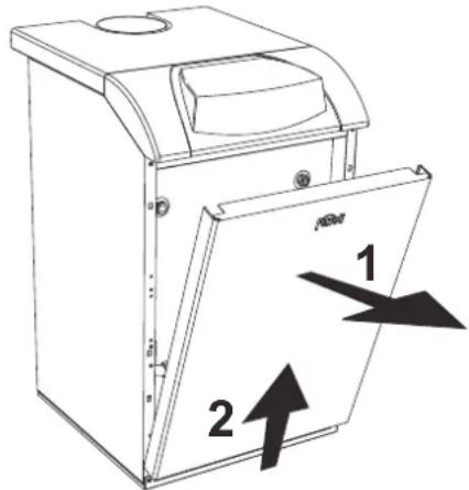
pnc.18-OTKpbITne nepeDne naHeHn
OuHcTka KOTnA N DbIMOXoDa
Дя ВынОнHeHЯ OЧИТКI KOTNa CNeДуITE (pnc.19) HIXeKpNBeDEHbIM yka3aHnM:
3akpoTe ra3OBbB BeHTINb, yCTaHOBnEHbI nepeI KOITNOm, I OTKIOUHTe arperatOT cETN 3JIeKTPoNTAHNA.
CHIMMTEJnueByIO naHEnbKOTna
- IopHmMITE Kpbikky Koxyxa, OKa3bBaHa Hero daBneHne CH3y BBepx.
CHIMMTE TENNON3OJRAUIO C npepbBaTeTn TAYI.
CHNMMTE PNTy,3akpbBaIOUOyIO DbIMOByIO Kamepy.
- demOnHtpyTe 6JOK ropEnok (cm. cneDyUoU npaparpaΦ).
- YnCTnte kamepy no HanpaBneHIO CBepx BYHn3 C NOMOsbIe epwa.
C nomoBIO nbilecoCA HCTHTe TpybOpBOOdb ydaHnnpoKTOB CropaHn, coedHHoune UyHyHhIe 3JeMeHtBJ KOpNyca KOTna.
- UctahOBITE Ha MeCTO BCE pahee demoHTnpOBaHHbIe DeTaJIIN, 3aTeM npOBepbTe repMeTHNUHOCTb Ra3OBON CNTEmbl IN KaHAIJOB CNTEmbl RopeHnA.
- PnB BInIOJIHEMN OUICTKn 6bpaIaIe BHIMAHHe Ha To, YTO6bI He NOpEINb 6aIIIOH TepMOCTaTaNbIMOBbIX Ra30B, paCNOIOKeHHb IN 3aIHe Nactn DbIMOBON KAMEpsI.
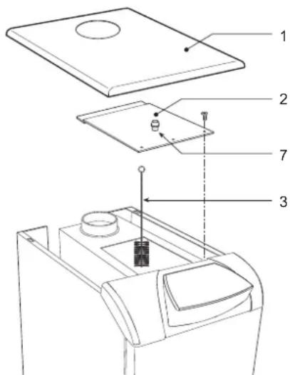
pnc.19-OuNCTKaKoTna
1
BepxnaHnKoxyxa
2
ПлNTаЗakрытЯДьIMOBОККAMерbl
3
Epw
7 Pp6ka OTBepCTnI nI npoeHnaHaJIa3a DbIMOBbIX Ra3OB
AHaJIIN3DbIMOBbIXra3OB
BHTPNKOTn, B BEPXHn qaTn ppebIbaTeIa Tn, PpeDyCMOTpeHa OHa ToKa OT6pa npo6 DmMOBbIX ra3OB (no3.7 - pnc.19).
Tc05bI npOn3BecTn H3MepeHne, Heo6xOJIMMo BblONHHTb CJeNyUeNe onepaun:
- CHINMTE BEPXHHOIO naHEnb KOTna
- CHIMMTE TENNON3OJNAIO C npepbBATEJRA
- CHIMMTE np6ky OTBepCTnO T60pa DbIMOBbIX Ra3OB;
- BCTaBbTe DaTHNK BOTBEpNCThe
- 3anyctnte pexn m TEST
- Ndooknte 10-15 MNHT dnaCTa6n3aun KOtna
- PpOu3BcHTN3MepeHne
PeybTaBbAaHn30B, BblnoHHeHbIX do cta6Hn3aun KOTna, Moryr 6bTb
Demontaxn ouhcTka 6Joka ropeJOK
DEmoHTaK 6IOKA rOpeJIOK OcyueCTBnIeTcra CneDuIouMM o6pa30M:
- ObecToBte arperat n 3akpoTe BEHTInb noaun ra3a, yCTaHOBnEHbN nepeKOTnOM;
OTBnHTte raKy kpenneHr Tpy6bl noDbOda r3a;
Pa3BHTnTe DBe raKn KpeIeHn Daepu KaMepb cropa Hn KpyHHbIM 3neMeHTa Kopnyca KoTna (pnc.20)
CHMMTE6nOKrpoEIOKBMecTeCDBepouKaMepbIcropAHIA
Pno3BnTe PnoBepky OOHCTKY OCHOBHO NINOTHOI ROPENK. JnA OHCTKN ROPENOK n 3eKTPoD0N NOb3yTEcB NCKNIHTeBHO HE MTAJIINHECKO IETKO IN CNKATbIM BO3dyXOM. He npmHReTHe XMMUeCKe CpeCTBA.
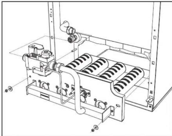
pnc.20-EmoHTax ropeNOK
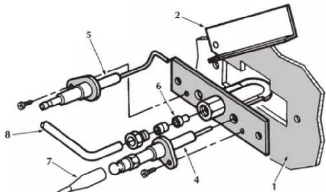
Hnnotna ropelka
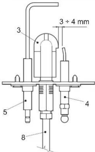
pnc.21-PnnoTnaR ropenka
1 DBepuKaMepeBcropaHn
2CMOTPOBAIDbepua
3 NIOOTHaR rOpEnKa
4 ΘneKtpoD po3xura
5 Cnepaun 3JektpoD
6 NnoTHaΦopcyHka
7 3neKtpnueckn Ka6eBbBICOKoHnpanjKeHH
8 Tpy6ka nodaa rasa
4.4 HenncnpabHocTHn cnoc6 ycTpaHHeHHa
DnarHoctNka
KOTEN OCHAUEN COBPEMENHO CNTEMO CAMODNARHOCTKN. B cnyae BO3HNOBOHENKAOKI-N60 HENCNPABHOCTCNMBN HENCPABHOCTN (no3 22 - pnc.1) COOTBETCYUKIO KOD HAUYHAIOT MMRTb HAUMNNEE.
HeKOTOpBHe HEnCnpaBHOCTn (O6o3HaAeMbIe 6yKB0n "A") npNBoT K NOCTORHHO B6oKnPOBKe KOJIa. B 3OM Cnyae cIeDyET npOn3BcTe n C6poc , HxKAB KnaBHy RE- SET (no3.8 - pnc.1) B TeHHeN 1 TcyeHne 1 TcyeHne 1 TcyeHne 1 TcyeHne 1 TcyeHne 1 TcyeHne 1 TcyeHne 1 TcyeHne 1 TcyeHne 1 TcyeHne 1 TcyeHne 1 TcyeHne 1 TcyeHne 1 TcyeHne 1 TcyeHne 2 EcnN KOtEN He BKIOHTTC, To Heo6XoIMMo YcTpaHTb HEnCnpaBHOCTb.
Дугия Немпразьности (обздачаимьдь Бквов "F")npИБОТКВРЕМСНОПКOBКБЕКOTЛА,КOTOPA"CHIMAETCByaTOMATYNECHKA,KAK TOLКВБЕМСНОПКOBK,БИЗBAUBAССРаБТВИЗЕ 6LOKNIPKOBNK,BO3BPSAuaTcER BДONPYNTMNBLE pRpeDJIb.
Ta6nua.2-Ta6nua HncnpaBHOCTe
| КoД нecираловоста | Hecinpapbnoctb | Воимочь рірочь | Спесоб устория |
| A01 | He npovckodn pOZKKI ropeKIN | Осутstбeн re3a | Посьергve, УТОЕ РОДМАБно NOCTYПЕВ в КOTEN, И сTOЕ ГAZIMРОБСБОВ SFТРАПЕН Bocdux |
| Hecinpapbnoctb cneJDAEJO mIM NOOKHRAOJOE 3NOKTPODA | Посьергve AneKTPUCHVMe COEDHINH 3NOKTPODA; ybeDInTEC6, УТОЕ ПОВAPMILNO yCTAHOBHIV IN HTO HAI ETO NOBPXRHOCTH ME MMOTCR OTNOMHIN | ||
| HecinpapbNoI rAOBbI KANAN | Посьергve rAOBcKII KIANANH 3MENHITe ETO, eCIN ITO BEOXODMO | ||
| HmKAR MOUHOCb PocZKMTa | PernylmpuHme MOnHOCb POZKMTa | ||
| A02 | Индikakuaя habлчигу plamamHIM pR Hepabotakoiu ropeKIN | Hecinpapbnoctb 3JekTePOda | Посьергve kABeMbI bOeCDHINH 3NOKTPODA HOHKSALIM |
| Hecinpapbnoctb 3NOKTPOHNO pOJIbI | Посьергve AneKTPONHIO pOJIbI | ||
| A03 | CpaBabahnlo yctpoKCTBa 3aazHbI ot Hepabotakoiu Ro tempepatdy | Датчк cKSTeMbl OTOJIENH NOKPEXHIN | Посьергve пЯвлгьн cTAYTOKHII pOJIbI datyKIA CSteMbl OTNIOHIN |
| OToCtTBe MZKPIKIIHIM BDOI B CHTeMbl OTNIOHIN | Посьергve AneKTPUCHNIIH HACCO | ||
| Hapinok Bozdua B CHTeMbl OTNIOHIN | СуICTRE BODUX IS CVTCEMbl | ||
| F04 | CpaBabahnlo TeMocSTATA TEmpepatryb dMboLbIX RAZB (PIM CpaBabatbavHIN BTLO TeMocSTATA paObta KOTNA MxKlouaIaBcB a TcHMeB 20 MNYr) | PazOMHyt KTOHKT TEPMOCTATA dMBOvBX RAZO | Посьергve TePMOCTAT |
| OobBy CoeDAHINTELBOH KAbELI | Посьергve KaBefHbIe COeDAHINHIN | ||
| HapinabHIO HO BILBOHANBE pAaMePbI MIM ZaBbHINH dMIOOaD | ЗаменITE DlMIOXOD | ||
| A06 | OToCtTBe PhAKANA noote uKINa lo PocZK | Hickoe DaJIaHIN B CHTeMbl raOZaHbENHIN RAZEM | Посьергve Давлие RaZA |
| HAcTPOHa DAIINENH RAZA B ROPEKte CTOKI HA MIMYUMe | Посьергve Давлие RaZA | ||
| F10 | Hecinpapbnoctb dAaTHMIZ 1 NOAaIeBO OTonlntelHNO KOTYPA | Датчк TOpRKeDN | Посьергve KaBefHbIe COeDAHINHIN |
| KopOTKRe ZAMKIIHAME CoeDAHINTELBOH KMaBEn | ЗаменITE DATYK | ||
| OObBy CoeDAHINTELBOH KAbELI DAtyKIA | Посьергve AneKTPONHIO | ||
| F14 | Hecinpapbnoctb dAaTHMIZ 2 NOAaIeBO OTonlntelHNO KOTYPA | Датчк TOpRKeDN | Посьергve AneKTPONHIIb COeDAHINHIN |
| KopOTKRe ZAMKIIHAME B CoeDAHINTELBOH KMaBEn | ЗаменITE DATYK | ||
| OObBy CoeDAHINTELBOH KAbELI DAtyKIA | Посьергve AneKTPONHIO | ||
| F34 | HapinokHnme NaTaNH NkIK 170 B. | Hecinpapbnoctb C ToCn 3NOKTPOHNTAHIN | Посьергve COSTORHE CHTeMbl 3NOKTPOHNTAHIN |
| F35 | Hecipomalhag Nactota cetBorO Tok | Hecinpapbnoctb C ToCn 3NOKTPOHNTAHIN | Посьергve COSTORHE CHTeMbl 3NOKTPOHNTAHIN |
| F37 | HaeepHOg DaIaHIne aQbI b CHTeMbl OTonlntelHNO KOTYPA | OToCtTBe BOBb B CHTeMbl | Посьергve AneKTPONHIIb COeDAHINHIN |
| Pene PaIaHINBOO BOBb He NIOJKNOH IMN IOBpExDhen | Посьергve COSTORHE DATYK | ||
| F39 | Hecinpapbnoctb dAaTHMIZ 8nAnHIN TEMpepatyBu | IopEczHIne DAIaHIN BOBb CHTeMbl | Посьергve KaBefHbIe COeDAHINHIN |
| OToCtTBe MZKPIKIIHAME KAbELI | ЗаменITE DATYK | ||
| OToCtTBe MZKPIKIIHAME KAbELI | Посьергve KaBefHbIe COeDAHINHIN | ||
| F40 | HaeepHOg DaIaHIne aQbI b CHTeMbl OTonlntelHNO | BbOcOe DAIaHIN | Посьергve CHTeMbl OTNIOHIN |
| BbOcOe DAIaHIN | Посьергve COSTORHE PREDOXPHENHIO KlANANA | ||
| OObBy CoeDAHINTELBOH KAbELI | Посьергve PaIaHmTEHINHIN | ||
| A41 | ItoLoxeHIne DaTMyOB KlAnaHa | Датчк TAmpepatryb BOBb B NIOAaIeCMb KOHType OTOnlntelHNO C NIOAaIeUe | Посьергve пявлгьн cTAYTOKHIIb IN pAboIb DATYK C CHTeMbl OTNIOHIN |
| F42 | Hecinpapbnoctb DaTMya CHTeMbl OTonlntelHIN | Датчк NOBpExDhen | ЗаменITE DATYK |
| F47 | Hecinpapbnoctb DaTMya DaTMya BOBb B CHTeMbl OTonlntelHIN | OObBy CoeDAHINTELBOH KAbELI | Посьергve KaBefHbIe |
| A48 | Hecinpapbnoctb rAOZBOrO KlAnaHa | Hecinpapbnoctb KABeHbIX CoeDAHINTELBOH KAtaHa | Посьергve KaBefHbIe COeDAHINHIN |
| Hecinpapbnoctb rAOZBOrO KAtaHa | ЗаменITE RAZOBbI KIanan | ||
| Hecinpapbnoctb 3AaKTPONHIO NtAlb | ЗаменITE AneKTPONHIO NtAlb | ||
| A49 | Hecinpapbnoctb rAOZBOrO KlAnaHa | Hecinpapbnoctb KABeHbIX CoeDAHINTELBOH KAtaHa | Посьергve KaBefHbIe COeDAHINHIN |
| IdeKetbI YAOZBOrO KAtaHa | ЗаменITE RAZOBbI KIanan | ||
| Hecinpapbnoctb 3AaKTPONHIO NtAlb | ЗаменITE AneKTPONHIO NtAlb |
5.XAPAKTEPNCNTKINTEXHNQECKNE DAHHbIE
5.1 Pa3MepbI, MecTa noDKnIOUeHm N OCHOBHbIe 3JIeMeHTbI KOTla
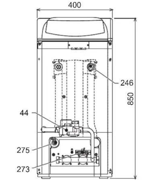
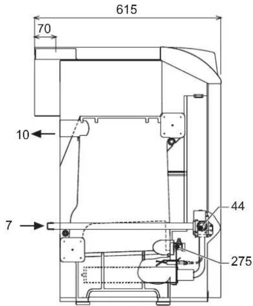
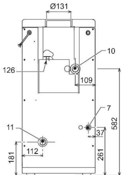
pnc.22-7a6apntHbIe pa3MepbI n npncoeHHENH PEGASUS D 23
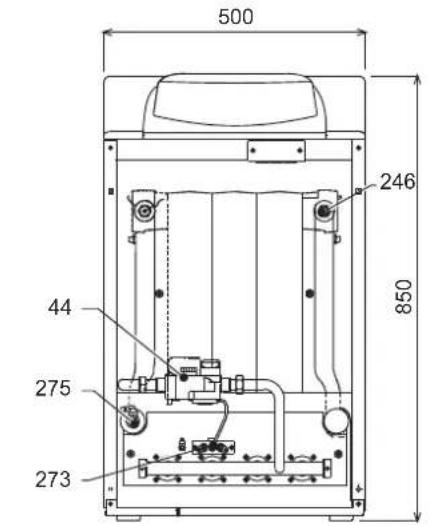
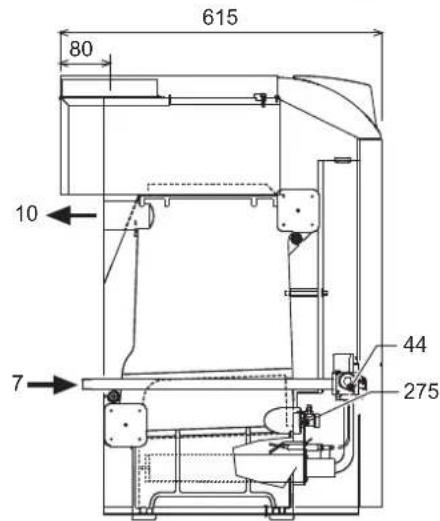
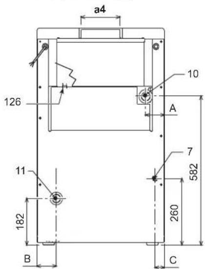
pnc.23-Pa3mepbI npncoeDHHnHnMoD.PEGASUS D 32 n PEGASUS D 45
| A | B | C | a4 | |
| Pegasus D 32 | 116 | 119 | 47 | Ø 131 |
| Pegasus D 45 | 73 | 76 | 36 | Ø 151 |
7 PnOBoDra3a-01/2"
10 TpybonpoBOD noDauH BOdbI BCNTeMy OTonneHn - 0 1"1/2
11 06paTHbI TpyboOpBOc nCTeMbI OTOnJIeHnR -0 1"1/2
44 RaObBn KnaNaH
126 TepmoCTaT TemnepaTybl npOdyKTOB cropaHna
246 DaTnK daBJeHnA
273 NnoTHa ropeJka
275 CnBHOI KpaH CNTeMb IOTONNEHIN
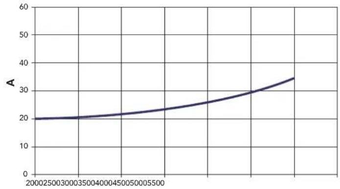
5.2Inpabnueckoe conpoTHneHne cHcTeMb
COnpoTnBHeHne BoaHoro KOnHpaa
B
pnc.24-1npabnueckoe conpotnbneHne cnCTembl
AM6ap
B PaCxOJ n/4
5.3 Ta6mua texHnuecknx daHHbIX
| Параметр Edmнua | Калория | Величина | Величина | Величина | |
| Морей 23 32 | 45 | ||||
| Колесства ленистов kBt 3 4 | 5 | ||||
| Мас. теллоронь радллость | kBt | 25.3 | 34.9 | 49.5 | (Q) |
| Мин. теллоронь радллость | kBt | 10.1 | 14.9 | 18.7 | (Q) |
| Мас. теллорь мошонь в рожиме отолленяя | kBt | 23.0 | 32.0 | 45.0 | (P) |
| Мин. теллорь мошонь в рожиме отолленяя | kBt | 8.8 | 13.0 | 17.2 | (P) |
| Клд P'max (80-60°C) | % | 90.9 | 91.7 | 90.9 | |
| Клд 30% | % | 91.3 | 91.5 | 91.6 | |
| Клaddафхөнгөнөнөнөнөнөнөнөнөнөнөнөнөнөнөнөнөнөнөнөнөнөнөнөнөнөнөнөнөнөнөнөнөнөнөнөнөнөнөнөнөнөнөнөнөнөнөнөнөнөнөn | ★★ | ||||
| Клaddаххүллс NOx | 2 | 2 | 2 | ||
| Форсуний рорей G20 | 甲x x Q | 2x2.803x | 2.80 | 4x2.80 | |
| Дааленiec поданура G20 | Mбap | 20 | 20 | 20 | |
| Мас. даленiec поданураллогу каллар G20 | Mбap | 15 | 13 | 15 | |
| Мин. даленiec поданураллогу каллар G20 | Mбap | 2.5 | 2.5 | 2.5 | |
| Мас. расхod радллог G20 | M' | 2.68 | 3.69 | 5.24 | |
| Минималынй расхod радллог G20 | M' | 1.07 | 1.58 | 2.08 | |
| Форсуний рорей G31 | 甲x x Q | 2x1.753x | 1.75 | 4x1.75 | |
| Дааленiec подану радллог G31 | Mбap | 37 | 37 | 37 | |
| Мakimалынhoe даленiec в рожиме G31 | Mбap | 35 | 31 | 35 | |
| Минималынhoe даленiec в рожиме G31 | Mбap | 6 | 6 | 6 | |
| Мakimалынай расхod радллог G31 | K' | 1.98 | 2.73 | 3.88 | |
| Минималынай расхod радллог G31 | K' | 0.79 | 1.17 | 1.54 | |
| Мakimалынhoe расхod даленiec в р�ддөнөнөнөнөнөнөнөнөнөнөнөнөнөнөнөнөнөнөнөнөнөнөнөнөнөнөнөнөнөнөнөнөнөнөнөнөнөнөнөнөнөнөнөнөнөнөнөнөнө网 | бap | 6 | 6 | 6 | (PMS) |
| Минималынhoe расхod даленiec в р�ддөнөнөнөнөнөнөнөнөнөнөнөнөнөнөнөнөнөнөнөнөнөнөнөнөнөнөнөнөнөнөнөнөнөнөнөнөнөнөнөнөн æтл'tы | бap | 0.8 | 0.8 | 0.8 | |
| Мас. теллоратура отолленяя | °C | 95 | 95 | 95 | (max) |
| Оььм Bodу в сүлөнөнөнөнөнөнөнөн | L | 9.1 | 11.6 | 14.1 | |
| Стrelны zasstы | IP | XOD | XOD | XOD | |
| Hашихөнөн пітаняя | B/TU | 230/50 | 230/50 | 230/50 | |
| Пл tradeэнөнөнөн радллог мошонь | Вt | 15 | 15 | 15 | |
| Вес похкгену кота | кt | 106 | 136 | 164 | |
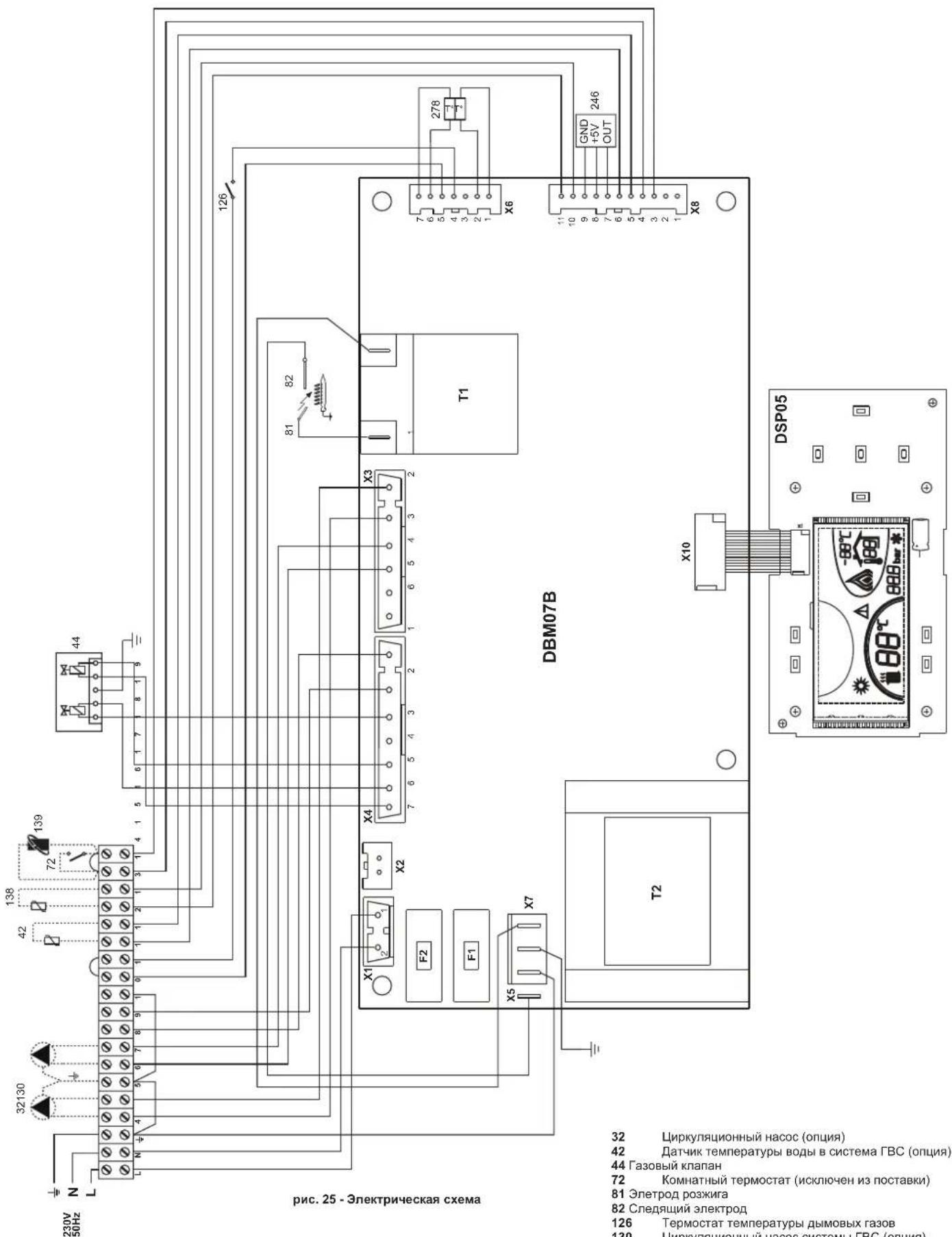
32 LnpkyIauHnHbHacoc(onu)
42 TATyHK TEMnepaTypbI BOdbI B CnCTema FBC (onu)
44 Ra3OBbI KnanaH
72 KomhaTHbI TepMOCTaT (NCKIOHcH N3 NOCTABKN)
81 ΘnetpoD po3Knra
82 Cnejauu 3nEeKtpo
126 TepMOCTaT TEMNEpatpybI dbIMOBbIX ra3OB
130 LpkyraonHHbHacoccnTeMbBC(onua)
138 DAtyHK HApxHOn TeMnepaTpybI (NCKJIOUeH N3 NOCTABK)
139 EINHnua nomeueHHna (NCKIOeHa n3 noCTaBn)
246 DaTnK daBneHn
278 KomboHpoBaHHbI daTynk (3aunTa+ OtponHeHne)
IT LA MARCATURA CERTIFICACHE I PRODOTTI SODDISFANO I REQUISITO FONDAMENTALI DELLE DIRTTIVE PERTINENTI IN VIGORE.
LA DICHIAZAIONE DI CONFORMITA PUO ESSERE RICHIESTA AL PRODUTTORE.
THE DECLARATION OF CONFORMITY MAY BE REQUESTED FROM THE MANUFACTURER.
FR LE MARQUAGE 6EATTESTE QUE LES PRODUITS SONT CONFORMES AUX EXIGENCES ESSENTIELLES DE L'ENSEMBLE DES DIRECTIVES QUI LEURS SONT APPLICABLES.
LA DÉCLARATION CE DE CONFORMITE PEUT ÉTRE DEMANDÉE AU FABRICANT.
UK MAPKYBAHH C 3ACBIIDYE BIDNOBIDHICTb BNPO6IB OCHOBHIM BNMOTAM INPEKTNB,IIIOUHX Y FAJY3I.
DEKJIAPAciIO IPO BIIDIOBIDHICTb MOXHA 3AINTATN Y BNIPOBnKA.
RU MAPKINPOBKA CENIOITBEPKDAET,TOIPODyKUNA COOTBETCTBYET OCHOBHbIM TPE6OBAHnM COOTBETCTBYIOUx DEICTBYIOUx INPEKTNB.
DEKJIAPAUZIO COOTBETCTBNI MOXET BbITb 3ATPE6OBAHA Y IPOUN3BOIDNTIEL.

EAC
FERROLI S.p.A.
Via Ritonda 78/a 37047 San Bonifacio - Verona - ITALY
www.ferroli.com


- OPERATING INSTRUCTIONS
- Introduction
- Key
- Lighting and turning off
- Boiler lighting
- Turning the boiler off
- Shutting down the boiler for prolonged periods
- Adjustments
- Summer/Winter Swithover
- Heating temperature setting
- DHW temperature adjustment
- Room temperature adjustment (with optional room thermostat)
- Room temperature adjustment (with optional remote timer control)
- Sliding temperature
- Compensation curve and curve offset
- Adjustments from Remote Timer Control
- Water system pressure adjustment
- INSTALLATION8
- General Instructions
- Place of installation
- Plumbing connections
- Water system characteristics
- Antifreeze system, antifreeze fluids, additives and inhibitors
- Connection to a storage tank for domestic hot water production
- Gas connection
- Electrical connections
- Connection to the electrical grid
- Room thermostat (optional)
- Accessing the electrical terminal block
- Air/fume ducts
- SERVICE AND MAINTENANCE
- Adjustments
- Turning on TEST mode
- Heating system output adjustment
- Gas conversion
- Start-up
- Before lighting the boiler
- Lighting
- Checks during operation
- Maintenance
- Seasonal Inspection of the boiler and flue
- Opening the front panel
- Cleaning the boiler and flue
- Removing and cleaning the burner assembly
- Pilot burner assembly
- Troubleshooting
- Diagnostics
- TECHNICAL DATA AND CHARACTERISTICS
- Loss of head
- Wiring diagram
- FR
- DISPOSITIONS GÉNÉRALES
- Raccordement gaz
- Raccordements electriques
- YbIMKHeHHH i BmMkaHH
- YbIMKHeHH KOTna
- BumKHeHHKOtNa
- TpBaJIe BUMKHeHH KOTJa
- PerylkuBaHHa
- NepemkkannJito/3nMa
- PerynboHHa TemnepaTpy onanenHH
- PeryIIOBaHHaTeMnepaTpyrnapaO caHTexHIO BODN
- Peryiobahn KIMhaTHOI TEMnepaTyPi (BMOHTOBAHM KIMHATHM TepMoCTaTOM)
- PerynoBaHHaKimHaiTeMnepaTyPi (3a DonomoroHO DnctahuiHoro xpoHOCTaty -Onu)
- Pyxoma notocha temnepayps
- KomneHcauiHa KpBa Ta nepeMeiueHH KpBHX
- XapakTepeCTNKBODN B KOHTpy onaJIeHHA
- Cnctema 3axncty BiD 3amep3aHn, aHTnΦpn3n, do6aBKn Ta iHri6itopn
- PiEaHnHDo6oHnepyDnraPaeoCaTExHIOBou
- YMOBHI No3HaueHHA
- 3.4Пдкнluоунгra3y
- EneKtpnHi 3'cDHaHn
- PiknouenHa o enektpuHoi Mepeki
- KIMHATNII TepMoCTaT (oncia)
- 3.6Pi'cHaHHoDAMOXOy
- EKCNJYATAUi I TEXHlHE OBCJLYROBYAHHu
- PervnoBaHHa
- YbIMKHeHH TectoBOro pexmmy TEST
- PerynIOBaHH noTyKHOCTI onAnIOBaNbHOro KOHTpy
- IpebeedeHHa iHnra3 KINBneHH
- Nyck B ekcnnyatauio
- Nepu Hix yBimkhytn KOTeI
- 3anyck
- Ipebeipkn niicac po6oTn
- 4.3Texhiueo6cnyrovbaHHa
- Ce3oHHI nepeBipKn KOTna n DmOxidy
- BiDkpnTTnpeHboi nahei
- OuHcHnKoTnaNIMoxiNy
- Demontax Ta ouuueHHy By3ny nabHnKIB
- YcyhenHHHecnpabHOCTe
- Дяагостпka
- 5.XAPAKTEPNCTIKNTA TEXHiHi DAHI
- Po3mipn. Micu npncdHaHHa Ta rONoBHi KOMnoHeHTn
- Btpatn Hanopy
- BtpaTH Hanopy 360ky BODN
- Ta6nua texHiuHx daHx
- PECYPCPA60TbIMCPOKCLJXKbbl
- NaHemb ynpabneHn
- IereHda
- BkIIOUeHne N BbIKIOUeHne
- OTcyTCTBnE 3JNEKTPoNTaHnKoTla
- Bknouehne kOtna
- BbIKIOueHne KOTna
- IpoJIOJIKHTeJIbHOe OTKnIouHeHne KOTna
- Perynipobkn
- Perynpobka TemnepaTybI BODI B CNTEme OTonJIeHn
- PerynpoBkA TeMnepatpyb B CnCTeMe ropyeo BodochaKeHnra (TBC)
- Perynpobka Temnepatpyb BO3dyxa B NOMeueHHN (C NOMOuHO ONHNOHOro Tepmoctata Temnepatpyb B NOMeueHHN).
- Perynpobka TeMnepatypbI BO3dyxa B NOMeueHNN (C NOMOUsBO ONUHOHOrO yCTPOHCTBa DcTainepom)
- Плаваюцая Temnéратура
- KomneHcaunOHnKa KpNBa n CMeueHHe KpNBbIX
- Perynpobahne c ndctanchoHHoro nybta ynpablenra c TaMepor
- PerynpoBaHne daBHeHH BODbI CnCTeMe OTonJeHH
- YCTAHOBKA
- Yukazamaо obuero xapaktepa
- Mecto yCTaHOBKM
- 3.3IpaBnueckne coeHHeHHa
- XapakTepeNTKBOBdI DnCCTEmbOtonneHn
- CnCTema 3aunTbO T3amep3aHn,KnKne aHTnΦpnsbl,do6abkn HnHn5ntopbl
- CoeHHeHc6oJIepomnIgBC
- JereHda
- PpncoeHHenne Kra3onpoBovdy
- 3neKtpnueckne coeHnHeHn
- IopKluoyehne K cetn 3neKtponntaHn
- TePMoCTaKOMHaTHoN TeMnepaTpby (onu)
- DocynK6nOKy3aXMMOB
- NpoknoueHne KOTNa KdbIMoOTbOy
- YXOD IN TEXHNU ECKOE OBCNJYKUBAHNE
- PerynipobKn
- AKTINBaunpexma TEST
- PerynpoBka MoUHOCTH CNTeMbI OTONJIeHNIA
- IpehaTpoKaHa npyroTnra3a
- BbOaB 3KcnnyatauHIO
- IpeBkHoueHHemKoTna
- BkHouyHe
- KohtpOlbHbIe onepaun, BblIOJIHReMbIe BO BpeMpa60tbl
- TexHHueckoe 06cnykBaHne
- Ce3oHHbIe npOBepKn KOtNa n DblMOxOda
- OtkpbItne nepedNe naneJin.
- OuHcTka KOTnA N DbIMOXoDa
- AHaJIIN3DbIMOBbIXra3OB
- Demontaxn ouhcTka 6Joka ropeJOK
- HenncnpabHocTHn cnoc6 ycTpaHHeHHa
- DnarHoctNka
Brand : FERROLI
Model : Pegasus D
Category : Boiler