
Pegasus - Central heating boiler FERROLI - Free user manual and instructions
Find the device manual for free Pegasus FERROLI in PDF.
| Product Type | Gas central heating boiler |
| Brand | Ferroli |
| Model | Pegasus (range 67-107 2S) |
| Dimensions (H x W x D) | Height: 760-1100 mm, Depth: 100-120 mm (width not specified) |
| Weight | 275-390 kg depending on model |
| Power supply | 230 V - 50 Hz, 30 W |
| Gas supply | Natural gas (G20, 20 mbar) or LPG (G31, 37 mbar) |
| Maximum thermal power | 73,3 - 117,0 kW depending on model |
| Maximum useful heating power | 67,0 - 107,0 kW |
| Efficiency (Pmax 80-60 °C) | Up to 91,5 % |
| Efficiency class (Directive 92/42 EEC) | ★★ |
| NOx emission class | 2 |
| Maximum heating service pressure | 6 bar |
| Maximum operating temperature | 95 °C |
| Water capacity | 19,1 - 29,1 L depending on model |
| Draft type | Open chamber (type B11BS) |
| Main functions | Central heating and domestic hot water (DHW) production |
| Hydraulic connections | Flow/return: 1"1/4, gas: 3/4" |
| Safety devices | Safety thermostat (110 °C), flue thermostat, ionization flame control, water pressure switch (optional) |
| Maintenance and cleaning | Annual cleaning of burners and boiler body, check flue ducts, check water pressure (1 bar cold) |
| Spare parts and repairability | Original spare parts, gas conversion kit available |
Frequently Asked Questions - Pegasus FERROLI
User questions about Pegasus FERROLI
0 question about this device. Answer the ones you know or ask your own.
Ask a new question about this device
Download the instructions for your Central heating boiler in PDF format for free! Find your manual Pegasus - FERROLI and take your electronic device back in hand. On this page are published all the documents necessary for the use of your device. Pegasus by FERROLI.
USER MANUAL Pegasus FERROLI
- outweighs the costs of developing and maintaining a new technology.
dot attenuaso ilNumero Verde 800 59 60 40.
- Carefully read the instructions contained in this instruction booklet.
- After boiler installation, inform the user regarding its operation and give him this manual, which is an integral and essential part of the product and must be kept with care for future reference.
- Installation and maintenance must be carried out by professionally qualified personnel, according to current regulations and the manufacturer's instructions. Do not carry out any operation on the sealed control part
- Incorrect installation or inadequate maintenance can result in damage or injury. The Manufacturer declines any liability for damage due to errors in installation and use or failure to follow the instructions.
- Before carrying out any cleaning or maintenance operation, disconnect the unit from the power supply using the system switch and/or the special cut-off devices.
- In case of a fault and/or poor operation, deactivate the unit and do not attempt to repair it or directly intervene. Contact professionally qualified personnel. Repair/replacement of the products must only be carried out by professionally qualified using original spare parts. Failure to comply with the above could affect the safety of the unit.
- This unit must only be used for its intended purpose. Any other use is considered improper and therefore dangerous.
The packing materials are potentially hazardous and must not be left within the reach of children. - The images given in this manual are a simplified representation of the product. In this representation there may be slight and insignificant differences with respect to the product supplied.
2. INSTALLATION
2.1 Introduction
Dear Customer,
Thank you for choosing PEGASUS 67 ÷ 107 2S, a floor-standing boilerFERROLI featuring advanced design, cutting-edge technology , high reliability and quality construction. Please read this manual carefully and keep it for future reference.
PEGASUS 67± 107 2S is a high-efficiency heat generator with low NOx emissions for central heating, running on natural gas or liquefied gas, equipped with an advanced electronic control system.
The boiler shell consists of cast-iron elements whose particular shape guarantees high exchange efficiency in all operating conditions, and an open-flue burner equipped with electronic ignition and ionisation flame control.
The boiler also has an automatic air vent valve, a 2-stage control thermostat and safety thermostat.
Thanks to the electronic ignition and flame control system, boiler operation is for the most part automatic.
The user only has to set the system temperature by means of the control thermostat.
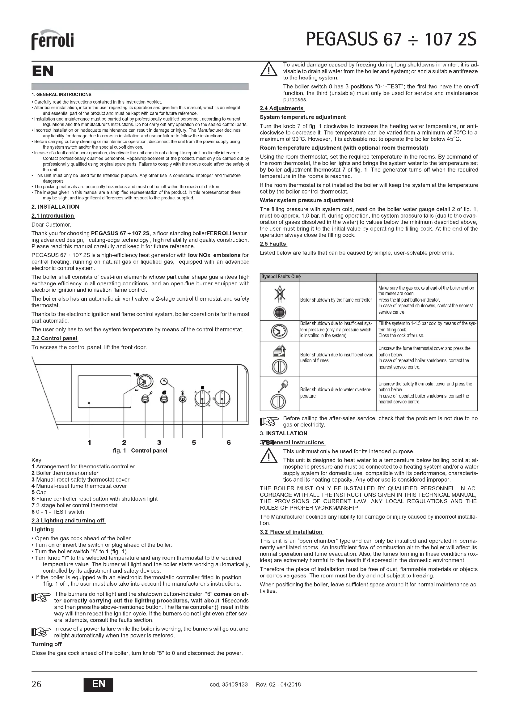
2.2 Control panel
To access the control panel, lift the front door.

fig. 1 - Control panel
Key
1 Arrangement for thermostatic controller
2 Boiler thermomanometer
3 Manual-reset safety thermostat cover
4 Manual-reset fume thermostat cover
5 Cap
6 Flame controller reset button with shutdown light
7 2-stage boiler control thermostat
80-1-TEST switch
2.3 Lighting and turning off
Lighting
- Open the gas cock ahead of the boiler.
- Turn on or insert the switch or plug ahead of the boiler.
- Turn the boiler switch "8" to 1 (fig. 1).
- Turn knob "7" to the selected temperature and any room thermostat to the required temperature value. The burner will light and the boiler starts working automatically, controlled by its adjustment and safety devices.
- If the boiler is equipped with an electronic thermostatic controller fitted in position 1fig. 1 of , the user must also take into account the manufacturer's instructions.

If the burners do not light and the shutdown button-indicator "6" comes on after correctly carrying out the lighting procedures, wait about 15 seconds and then press the above-mentioned button. The flame controller () reset in this way will then repeat the ignition cycle. If the burners do not light even after several attempts, consult the faults section.

In case of a power failure while the boiler is working, the burners will go out and relight automatically when the power is restored.
Turning off
Close the gas cock ahead of the boiler, turn knob "8" to 0 and disconnect the power.

To avoid damage caused by freezing during long shutdowns in winter, it is advisable to drain all water from the boiler and system; or add a suitable antifreeze to the heating system.
The boiler switch 8 has 3 positions "0-1-TEST"; the first two have the on-off function, the third (unstable) must only be used for service and maintenance purposes.
2.4 Adjustments
System temperature adjustment
Turn the knob 7 of fig. 1 clockwise to increase the heating water temperature, or anticlockwise to decrease it. The temperature can be varied from a minimum of 30ircC to a maximum of 90ircC . However, it is advisable not to operate the boiler below 45ircC .
Room temperature adjustment (with optional room thermostat)
Using the room thermostat, set the required temperature in the rooms. By command of the room thermostat, the boiler lights and brings the system water to the temperature set by boiler adjustment thermostat 7 of fig. 1. The generator turns off when the required temperature in the rooms is reached.
If the room thermostat is not installed the boiler will keep the system at the temperature set by the boiler control thermostat.
Water system pressure adjustment
The filling pressure with system cold, read on the boiler water gauge detail 2 of fig. 1, must be approx. 1.0 bar. If, during operation, the system pressure falls (due to the evaporation of gases dissolved in the water) to values below the minimum described above, the user must bring it to the initial value by operating the filling cock. At the end of the operation always close the filling cock.
2.5 Faults
Listed below are faults that can be caused by simple, user-solvable problems.
| Symbol Faults Cure | ||
| Boiler shutdown by the flame controller | Make sure the gas cocks ahead of the boiler and on the meter are open. Press the lift pushbutton-indicator. In case of repeated shutdowns, contact the nearest service centre. | |
| Boiler shutdown due to insufficient system pressure (only if a pressure switch is installed in the system) | Fill the system to 1-1.5 bar cold by means of the system filling cock. Close the cock after use. | |
| Boiler shutdown due to insufficient evaporation of fumes | Unscrew the fume thermostat cover and press the button below. In case of repeated boiler shutdowns, contact the nearest service centre. | |
| Boiler shutdown due to water overtemperature | Unscrew the safety thermostat cover and press the button below. In case of repeated boiler shutdowns, contact the nearest service centre. | |

Before calling the after-sales service, check that the problem is not due to no gas or electricity.
3. INSTALLATION
378 General Instructions
This unit must only be used for its intended purpose. This unit is designed to heat water to a temperature below boiling point at atmospheric pressure and must be connected to a heating system and/or a water supply system for domestic use, compatible with its performance, characteristics and its heating capacity. Any other use is considered improper.
THE BOILER MUST ONLY BE INSTALLED BY QUALIFIED PERSONNEL, IN ACCORDANCE WITH ALL THE INSTRUCTIONS GIVEN IN THIS TECHNICAL MANUAL, THE PROVISIONS OF CURRENT LAW, ANY LOCAL REGULATIONS AND THE RULES OF PROPER WORKMANSHIP.
The Manufacturer declines any liability for damage or injury caused by incorrect installation.
3.2 Place of installation
This unit is an "open chamber" type and can only be installed and operated in permanently ventilated rooms. An insufficient flow of combustion air to the boiler will affect its normal operation and fume evacuation. Also, the fumes forming in these conditions (oxides) are extremely harmful to the health if dispersed in the domestic environment.
Therefore the place of installation must be free of dust, flammable materials or objects or corrosive gases. The room must be dry and not subject to freezing.
When positioning the boiler, leave sufficient space around it for normal maintenance activities.
3.3 Plumbing connections
Important
The heating capacity of the unit must be previously established by calculating the building's heat requirement according to the current regulations. To ensure proper operation and long boiler life, the plumbing system must be adequately sized and complete with all the necessary accessories.
If the delivery and return pipes follow a path where air pockets can form in certain places, it is advisable to install vent valves at these points. Also, install a discharge device at the lowest point in the system to allow its complete emptying.
If the boiler is installed at a lower level than the system, it is advisable to provide a flow-stop valve to prevent the natural circulation of water in the system.
The temperature drop between the delivery manifold and the return to the boiler should not exceed 20ircC .

Do not use the water system pipes to earth electrical appliances.
Before installation, carefully wash all the pipes of the system to remove any residuals or impurities that could affect proper operation of the unit.
Carry out the relevant connections as indicated in fig. 13.
It is advisable to install shutoff valves between the boiler and heating system, allowing the boiler to be isolated from the system if necessary.

Make the boiler connection in such a way that its internal pipes are free of stress.
Water system characteristics
In the presence of water harder than 25irc Fr, it is advisable to use suitably treated water, in order to avoid possible scaling in the boiler caused by hard water, or corrosion produced by aggressive water. Due to its low thermal conductivity, scaling even just a few mm thick causes significant overheating of the boiler walls with consequent serious problems.
Water treatment is indispensable in case of very large systems (containing large amounts of water) or with frequent introduction of replenishing water in the system. If partial or total emptying of the system becomes necessary in these cases, it is advisable to refill with treated water.
Filling boiler and system
The filling pressure with system cold system must be approx. 1 bar. If, during operation, the system pressure falls (due to the evaporation of gases dissolved in the water) to values below the minimum described above, the user must bring it to the initial value. For correct operation of the boiler, when hot, its pressure must be approx. 1.5-2 bar.
3.4 Gas connection

Before carrying out the connection, make sure the unit is arranged for using the type of fuel available and carefully clean all the pipes of the gas system to remove any residues that could affect proper boiler operation.
The gas must be connected to the relevant connection (see fig. 13) in conformity with current standards, with a rigid metal pipe or with a continuous surface flexible s/steel tube, installing a gas cock between the system and boiler. Make sure all the gas connections are tight.
The capacity of the gas meter must be sufficient for the simultaneous use of all equipment connected to it. The diameter of the gas pipe leaving the boiler does not determine the diameter of the pipe between the unit and the meter; it must be chosen according to its length and pressure losses, in conformity with the current regulations.

Do not use the gas pipes to earth electrical appliances.
3.5 Electrical connections
Connection to the power supply
The boiler must be connected to a single-phase, 230 Volt-50 Hz electric line.

The unit's electrical safety is guaranteed only when it is correctly connected to an efficient earthing system in conformity with the current safety regulations. Have the efficiency and suitability of the earthing system checked by professionally qualified personnel; the Manufacturer declines any liability for damage caused by failure to earth the system. Also make sure the electrical system is adequate for the maximum power absorbed by the unit, as specified on the boiler dataplate, in particular ensuring that the section of the system's cables is suitable for the input.
The boiler is prewired and supplied with a connector located inside the control panel, arranged for connection to an electronic thermostatic controller (see wiring diagrams in sec. 5.5). It is also equipped with a three-core cable for connection to the electric line. The connections to the power supply must be made with a permanent connection and equipped with a double-pole switch with contact gap of at least 3mm , interposing fuses of max. 3A between the boiler and line. It is important to respect the polarities (LINE: brown wire / NEUTRAL: blue wire / EARTH : yellow/green wire) when making the connections to the electric line.
Accessing the electrical terminal block and components inside the control panel
To access the electrical components inside the control panel, follow the sequence in fig. 2. The layout of the terminals for the various connections is given in the wiring diagrams in the technical data section.

fig. 2 - Accessing the terminal block
Key
Undo the 2 self-tapping screws securing the boiler cover.
B Lift by pressing upwards and remove the cover held to the sides of the boiler by pins.
C Undo and remove the two screws and the two plates holding the control panel. D Turn the control panel forwards.
Any additional sensitive elements of the system's control and safety devices, temperature probe, pressure switch, thermostat bulb, etc., must be located on the delivery pipe within 40 cm of the boiler casing rear wall (see fig. 3).
Key
A System delivery
B System return
C 40 cm max.

fig. 3 - Delivery and return
The diameter of the connecting pipe to the flue must not be less than that of the connection on the anti-backflow device. Starting from the anti-backflow device it must have a vertical section at least 50 cm long. The current regulations must be respected regarding the dimensioning and installation of the flues and connection pipe.
The boiler is a B11BS type equipped with a safety device (fume thermostat) that stops the supply of gas and shuts down the unit in case of poor draught or disturbance in the fume exhaust. Unit shutdown is indicated on the display with the code F04 (ref. cap. 3.4). Restarting of the unit occurs automatically 20 minutes after the end of the fault that caused the problem. In case of repeated intervention of the device, contact qualified personnel to check the flue and chimney and eliminate the fume evacuation fault.

This safety device must never be tampered with or deactivated. Any operation on the device, or its replacement, must only be carried out by qualified personnel using the manufacturer's original replacement parts. A functional test must be carried out after any operation on the device.
3.6 Connection to the flue
The flue connection pipe diameter must not be less than that of the connection on the anti-backflow device. Starting from the anti-backflow device it must have a vertical section at least 50 cm long. Comply with the current regulations regarding installation and sizes of the flues and connection pipe.
The diameters of the anti-backflow device collars are given in table 1.
4. SERVICE AND MAINTENANCE
4.1 Adjustments
All adjustment and conversion operations must be carried out by Qualified Personnel.
The manufacturer declines any liability for damage or injury caused by unqualified and unauthorised people tampering with the unit.
Burner gas pressure adjustment
The boilers PEGASUS 67 ÷ 107 2S are arranged to run on natural or liquefied gas. The pressure setting and test are performed in the factory.
However, at first lighting, as there may be supply pressure variations, check and if necessary adjust the pressure at the nozzles, respecting the values given in the technical data table in sec. 5.3.
Pressure adjustment operations must be carried out with the boiler working, using the pressure regulator on the 2-stage gas valves (see fig. 4)
Preliminary operations:
- Light the boiler and turn the control thermostat knob to minimum.
- Connect a pressure gauge to the pressure point on the gas manifold pipe of the burner assembly (see part 14 of fig. 14).
- Remove the protection cap of the pressure regulator 4 of fig. 4.
Minimum power (1st stage) adjustment
- Turn the control thermostat knob slowly clockwise to the 1st click; the gas valve will thus be supplied only on connections A and B (see fig. 4).
- Turn the screw 6 of fig. 4, checking that the pressure matches the values given in the technical data table in sec. 5.3.
Maximum power (2nd stage) adjustment
- Turn the control thermostat knob to maximum; the gas valve will now be supplied only on connections A, B and C (see fig. 4).
- Turn the screw 5 of fig. 4, checking that the pressure matches the values given in the technical data table in sec. 5.3.
The adjustment operations must be performed uniformly on the pressure regulators of all the valves.
The gas pressures measured at the burner gas manifold must be read at least 30 seconds after making the adjustments, i.e. when the flame has stabilised.
On completing the adjustment operations, turn the burner on and off 2 - 3 times with the control thermostat and check that the pressure values are those just set; otherwise, it is necessary to make another adjustment to bring the pressures to the correct values.
Gas conversion
The unit can work with Natural gas (G20-G25) or liquefied gas (G30-G31) and is factory-set for use with one of the two gases, as clearly shown on the packing and dataplate. Whenever the unit has to be used with a different gas, a conversion kit will be required, proceeding as follows.
From natural to liquefied gas
- Replace the nozzles at the main burner and pilot burner, fitting the nozzles specified in the technical data table in sec. 5.3.
- Remove the small cap 3 (fig. 4) from the gas valve, screw the ignition "STEP" regulator 2 (contained in the conversion kit) onto the valve and refit the cap 3 on the regulator.
- Adjust the burner gas pressures for minimum and maximum power as described in the previous section, setting the values given in the technical data table of section sec. 5.3.
- Operations 2 and 3 must be performed on all the valves.
- Apply the sticker contained in the conversion kit, near the dataplate as proof of the conversion.
From liquefied to natural gas
Carry out the same operations described above, making sure to remove the ignition "STEP" regulator 2 of fig. 4 of the gas valve; the cap 3 of fig. 4 must be fitted directly on the valve.


fig. 4 - Gas conversion
Key of main components
1 Pressure point upstream
2 Ignition "STEP" regulator for liquefied gas
3 Plug
4 Protection cap
5 Pressure adjustment screw for max. power
6 Pressure adjustment screw for min. power (1st stage)
7 O-ring
8 Decrease
9 Increase
V Honeywell valve VR 4601 CB
Key of electrical connections
A+B= Connections fed for min. power (1st stage)
A+B+C=Connections fed for max. power (2nd stage)
4.2 Commissioning

Commissioning must be carried out by Qualified Personnel.
The following operations and checks must be made at first lighting, and after all maintenance work involving disconnection from the systems or work on safety devices or parts of the boiler.
Before lighting the boiler
- Open any shutoff valves between the boiler and the system.
- Check the tightness of the gas system, proceeding with caution and using soapy water to check for any leaks in connections.
- Fill the water system and make sure all air contained in the boiler and the system has been vented by opening the air valve on the boiler and any vent valves in the system.
Make sure there are no water leaks in the system or boiler.
Make sure the electrical system is properly connected.
Make sure the unit is connected to an efficient earthing system.
Make sure the pressure and gas flow values are those required for heating. - Make sure there are no flammable liquids or materials in the immediate vicinity of the boiler.
Lighting the boiler
- Open the gas cock ahead of the boiler.
- Vent the air from the pipe ahead of the gas valve.
- Turn on or insert the switch or plug ahead of the boiler.
- Turn the boiler switch (pos. 8 - fig. 1) to position 1
- Turn the knob 7 (fig. 1) to a value above 50ircC and that of the room thermostat (if present) to the required temperature. The burner will light and the boiler starts to work automatically, controlled by its adjustment and safety devices.
If, after correctly carrying out the lighting procedure, the burners do not light and the button light comes on, wait about 15 seconds and then press the above-mentioned button. The reset controller will repeat the ignition cycle. If the burners do not light after the second attempt, consult the sec. 4.4.
The boiler switch 8 has 3 positions "0-1-TEST"; the first two have the on-off function, the third (unstable) must only be used for service and maintenance purposes.

In case of a power failure while the boiler is working, the burners will go out and relight automatically when the power is restored.
Checks during operation
Make sure the fuel circuit and water systems are tight.
- Check the efficiency of the flue and fume ducts while the boiler is working
- Make sure the water is circulating properly between the boiler and the system.
- Check correct lighting of the boiler, by turning it on and off several times using the room thermostat or boiler thermostat.
- Make sure the fuel consumption indicated on the meter matches that given in the technical data table in cap. 5.
Turning off
To temporarily turn the boiler off, just set the boiler switch 8 (fig. 1) to 0.
To turn the boiler off for an extended period:
- Turn the knob of the boiler switch 8 (fig. 1) to 0;
- Close the gas cock ahead of the boiler;
- Disconnect the power to the unit;
To avoid damage caused by freezing during long idle periods in winter, it is advisable to drain all the water from the boiler and the system; or add a suitable antifreeze to the heating system
4.3 Maintenance

THE FOLLOWING OPERATIONS MUST ONLY BE CARRIED OUT BY QUALIFIED PERSONNEL.
Seasonal inspection of the boiler and flue
It is advisable to carry out the following checks at least once a year:
- The control and safety devices (gas valve, thermostats, etc.) must function correctly.
- The fume ducts must be free of obstructions and leaks.
The gas and water systems must be tight.
The burner and boiler shell must be clean. Follow the instructions in the next section.
The electrodes must be free of deposits and properly positioned (see fig. 11).
- The water pressure in the system when cold must be approx. 1 bar; otherwise bring it to that value.
The expansion tank, if present, must be filled.
- The gas delivery and pressure must correspond to that given in the technical data table (see sec. 5.3).
The circulating pumps must not be blocked.
Safety devices
The boiler PEGASUS 67 ÷ 107 2S is equipped with devices that guarantee safety in case of operation faults.
Manual-reset temperature limiter (safety thermostat)
This device prevents the water temperature in the system from exceeding boiling point. The maximum activation temperature is 110ircC
Resetting of the temperature limiter can only occur on cooling of the boiler (the temperature must drop by at least 10ircC ) and identification and consequent elimination of the problem that caused the shutdown. To reset the temperature limiter, unscrew the cover 3 of fig. 1 and press the button below.
Fume sensor (fume thermostat) safety device
The boiler is equipped with a fume evacuation control device (fume sensor - ref. 4 of fig. 1). In case of anomalies in the fume exhaust system with consequent return of burnt gases in the room, the unit shuts down. The antiwind grille is equipped with a temperature sensor bulb for detecting and controlling the fume temperature.
Any leaks of burnt gases into the room cause an increase in the temperature detected by the bulb, which causes the boiler to turn off within 2 minutes, shutting off the gas to the burner. If the fume sensor cuts in, unscrew the protection cover (ref. 4 of fig. 1) located on the control panel and manually reset the device. The boiler will resume operation.
If the sensor has to be replaced due to a fault, only use original accessories and ensure that the electrical connections and positioning of the bulb are correctly carried out.

The fume sensor must not be cut out for any reason!
Opening the front casing
To open the front panel of the boiler, refer to the sequence in fig. 5.

fig. 5 - Front panel opening

Before carrying out any operation inside the boiler, disconnect the electrical power supply and close the gas cock upstream.
Combustion analysis
A fume sampling point has been included inside the boiler, in the top part of the anti-backflow device (see fig. 6).
To take the sample:
1. Remove the boiler top panel
2. Remove the insulation placed over the anti-backflow device
3. Open the fume sampling point;
4. Insert the probe;
5. Adjust the boiler temperature to max.
6. Wait 10-15 minutes for the boiler to stabilise*
7. Take the measurement.

fig. 6 - Combustion analysis

Analyses made with an unstabilised boiler can cause measurement errors.
Burner assembly removal and cleaning
To remove the burner assembly:
- Disconnect the power supply and turn off the gas ahead of the boiler.
- Undo the two screws securing the electronic flame controllers to the gas valve (fig. 7) and remove them from the gas valves (fig. 8).
For models 97 2S and 107 2S with 2 gas valves, also undo the 2 screws securing the 2 electrical connectors that feed the second valve and remove them. - Disconnect the ignition and ionisation cables from the electrode assembly.
- Undo the nut fixing the gas supply pipe ahead of the gas valve (fig. 9). For models 97.2S and 107.2S, undo the 2 nuts.
- Undo the two nuts fixing the combustion chamber door to the cast iron elements of the boiler (fig. 10).
- Remove the burner assembly and combustion chamber door.
Check and clean the burners. Only use a non-metallic brush or compressed air to clean the burners; never use chemical products.
On completion, refit everything in reverse order.

fig. 7 - Undo the control unit screws

fig. 8 - Remove the control unit

fig. 9 - Undo the gas valve nut

fig. 10 - Undo the combustion chamber door nuts
Pilot burner assembly


fig.11 - Pilot burner
1 Combustion chamber door
2 Inspection door
3 Pilot burner
4 Ignition electrode
5 Detection electrode
6 Pilot nozzle
7 High voltage cable
8 Gas supply pipe
Cleaning the boiler and flue
For proper cleaning of the boiler (see fig. 12):
- Turn off the gas ahead of the unit and disconnect the power supply
- Remove the front panel of the boiler (fig. 5).
- Lift the casing cover by pressing upwards.
- Remove the insulation 5 covering the anti-backflow device.
- Remove the fume chamber closing plate and insulation.
- Remove the burner assembly (see previous par.)
- Clean from the top downwards, using a flue brush. The same operation can be carried out from the bottom upwards.
- Clean the fume evacuation ducts between the cast iron elements of the boiler shell with an aspirator.
- Carefully refit all the previously removed parts and check the tightness of the gas circuit and the combustion ducts.
- During cleaning be careful not to damage the bulb of the fume thermostat fitted on the back of the fume chamber.

fig. 12 - Boiler cleaning
1 Casing cover
2 Fume chamber closing plate
3 Flue brush
4 Combustion analysis plug
5 Insulation
4.4 Troubleshooting
| Fault Cause / Cure | |
| After several lighting attempts, the electronic controller shuts down the boiler. | Clean the pilot burner nozzles with compressed air. |
| Check the regular gas flow to the boiler and that the air has been eliminated from the pipes. | |
| Make sure the electrodes are correctly positioned and free of deposits (see fig. 11). | |
| Make sure the boiler is connected to an efficient earth connection. | |
| Check the connections at the ignition and ionisation electrodes. | |
| The electrodes are not discharging in the ignition phase. | Make sure the electrodes are correctly positioned and free of deposits (see fig. 11). |
| Control thermostat adjusted too low. | |
| Check the power supply. | |
| Check the connections at the ignition and ionisation electrodes. | |
| Check the connections at the electronic flame controller. | |
| Make sure LINE-NEUTRAL are not inverted and that the earth contacts are effi-cient. | |
| Check the inlet gas pressure and any open pressure switches. | |
| Reset the safety thermostat. | |
| Reset the fume thermostat. | |
| Make sure the room thermostat is closed. | |
| The burner burns poorly; flames too high, too low or too yellow | Gas valve filter dirty. |
| Check the gas supply pressure. | |
| Gas nozzles dirty. | |
| Make sure the boiler is not dirty. | |
| Make sure the ventilation in the room where the unit is located is sufficient for proper combustion. | |
| Smell of unburnt gas Make sure the | boiler is clean. |
| Check the flue draught. | |
| Check that gas consumption is not excessive. | |
| The boiler works but the tempera-ture does not increase | Check correct operation of the 2-stage control thermostat. |
| Make sure the gas valve 2nd stage operator (max. power) is fed. | |
| Check that gas consumption is not less than that provided for. | |
| Make sure the boiler is perfectly clean. | |
| Make sure the boiler is adequate for the system. | |
| Make sure the heating pump is not blocked. | |
| Temperature of water to the system too high or too low | Check correct operation of the 2-stage control thermostat. |
| Make sure the heating pump is not blocked. | |
| Make sure the characteristics of the circulating pump are adequate for the sys-tem. | |
| Explosion at burner. Delay on igni-tion | Make sure the gas pressure is sufficient and that the boiler shell is not dirty. |
| The control thermostat is reacli-vated with too great a temperature difference | Make sure the bulb is properly inserted in the sheath. |
| Check operation of the 2-stage thermostat. | |
| The boiler produces condensate Ma | ke sure the boiler is not operating at too low a temperature (below 50°C). |
| Check regular gas consumption. | |
| Check the efficiency of the flue. | |
| The boiler shuts down for no apar-e n t reason | Safety thermostat activation due to an overtemperature. |
| Fume thermostat activation. |

To avoid unnecessary expense, before calling the After-Sales Service make sure the boiler has not stopped due to no electricity or gas.
5. TECHNICAL DATA AND CHARACTERISTICS

5.1 Dimensions and connections
fig. 13 - Dimensions and connections
Table.1
| Type and model A B C | C | a1 heating return | a2 heating delivery | a3 Gas inlet | ||
| PEGASUS 67 2S | 760 100 | 180 1" | 1/4 1" 1/4 | 3/4" | ||
| PEGASUS 77 2S | 850 110 | 200 1" | 1/4 1" 1/4 | 3/4" | ||
| PEGASUS 87 2S | 930 110 | 200 1" | 1/4 1" 1/4 | 3/4" | ||
| PEGASUS 97 2S | 1020 | 110 | 200 1" | 1/4 1" 1/4 3/4" | ||
| PEGASUS 107 2S | 1100 | 120 220 | 1" 1/4 | 1" 1/4 3/4" |

5.2 General view and main components
fig. 14 - General view and main components
Key
1 Pilot burner assembly
2 Gas valve for all models
3 Electronic flame controller
12 2nd gas valve (only models 107 2S and 97 2S)
13 Boiler drain cock
14 Burner assembly
15 Burner pressure point
5.3 Technical data table
| Model | 67 2S | 77 2S | 87 2S | 97 2S | 107 2S | ||
| Number of elements | no. | 7 | 8 | 9 | 10 | 11 | |
| Max. heating capacity | kW | 73.3 | 84.2 | 95.2 | 106.0 | 117.0 | (Q) |
| Min. heating capacity | kW | 31.0 | 35.7 | 40.3 | 45.0 | 49.0 | (Q) |
| Max. heat output in heating | kW | 67.0 | 77.0 | 87.0 | 97.0 | 107.0 | (P) |
| Min. heat output in heating | kW | 27.3 | 31.4 | 35.5 | 39.6 | 43.0 | (P) |
| Efficiency Pmax (80-60°C) | % | 91.4 | 91.5 | 91.4 | 91.5 | 91.5 | |
| Efficiency 30% | % | 91.3 | 91.4 | 91.2 | 90.5 | 90.5 | |
| Efficiency class Directive 92/42 EEC | ★★ | ||||||
| NOx emission class | 2 | ||||||
| Burner nozzles G20 | no.x Ø | 6 x 2.80 | 7 x 2.80 | 8 x 2.80 | 9 x 2.80 | 10 x 2.80 | |
| Gas supply pressure G20 | mbar | 20 | 20 | 20 | 20 | 20 | |
| Max. gas pressure at burner G20 | mbar | 13 | 13 | 13 | 13 | 13 | |
| Min. gas pressure at burner G20 | mbar | 2.5 | 2.5 | 2.5 | 2.5 | 2.5 | |
| Max. gas delivery G20 | \( m^3/h \) | 7.76 | 8.91 | 10.07 | 11.22 | 12.38 | |
| Min. gas delivery G20 | \( m^3/h \) | 3.28 | 3.78 | 4.26 | 4.76 5.19 | ||
| Burner nozzles G31 | no.x Ø | 6 x 1.75 | 7 x 1.75 | 8 x 1.75 | 9 x 1.75 | 10 x 1.75 | |
| Gas supply pressure G31 | mbar | 37 | 37 | 37 | 37 | 37 | |
| Max. gas pressure at burner G31 | mbar | 35 | 35 | 35 | 35 | 35 | |
| Min. gas pressure at burner G31 | mbar | 6 | 6 | 6 | 6 | 6 | |
| Max. gas delivery G31 | kg/h | 5.74 | 6.59 | 7.45 | 8.30 | 9.16 | |
| Min. gas delivery G31 | kg/h | 2.43 | 2.80 | 3.16 | 3.52 | 3.84 | |
| Fume temperature Pmax | °C | 142 | 120 | 130 | 135 | 139 | |
| Fume temperature Pmin | °C | 95 | 87 | 89 | 92 | 94 | |
| Fume flow rate Pmax | g/s | 43.5 | 64.9 | 67.3 | 70.4 | 74.4 | |
| Fume flow rate Pmin | g/s | 36.7 | 55.2 | 60.0 | 64.6 | 65.6 | |
| Max. working pressure in heating | bar | 6 | 6 | 6 | 6 | 6 | (PMS) |
| Min. working pressure in heating | bar | 0.3 | 0.3 | 0.3 | 0.3 | 0.3 | |
| Max. heating temperature | °C | 95 | 95 | 95 | 95 | 95 | (tmax) |
| Heating water content | L | 19.1 | 21.6 | 24.1 | 26.6 | 29.1 | |
| Protection rating | IP | XOD | XOD | XOD | XOD | XOD | |
| Power supply voltage | V/Hz | 230/50 | 230/50 | 230/50 | 230/50 | 230/50 | |
| Electrical power input | W | 30 | 30 | 30 | 30 | 30 | |
| Empty weight | 275 304 | 333 362 | 390 | ||||

5.4 Diagrams
Pressure loss
Key
A Pressure losses m H 2O column
B Delivery m 3/h
5.5 Wiring diagrams

Connection wiring diagram
fig. 15 - Electrical connection diagram

Main wiring diagram
fig.16 - Main wiring diagram

Connections in broken lines to be carried out by the installer
Key
24 - Ignition electrode
32 - Heating circulating pump (not supplied)
44a-Gas valve
44b-2 no Gas valve (only models 97 2S and 107 2S)
49 - Safety thermostat
72 - Room thermostat (not supplied)
82 - Detection electrode
83 - Electronic controller
92 - Fume thermostat
98 - Switch
129 - Reset button with indicator lamp
159 - Test button
160 - Auxiliary contact
167a - Gas valve 2nd stage operator
167b - 2nd Gas valve 2nd stage operator (only models 97 2S and 107 2S)
170 - 1st stage control thermostat
171-2nd stage control thermostat
FR
1. AVERTISSEMENTS GÉNÉRAUX
3.4 Raccordement gaz

3.5 Raccordements electriques
3'EDHANH Tpy6n 3 Tpy6o NOBHHM MaTn diameTp He MeHue, Hx HA yCTAHOBU. POnHAAHO 3 AHTN NOBHHI ByTN BEPTKAnbHm PO3p13 3ABDOxHKe MEHUE NIBMetpa. UO CTocyETcbor 03pIMiY i YCTAHOBky DmOxOjB i CNOlyuHOro Tpy6onpoBody Do HIX, Heo6xIDHO BINIOBADttn CTaHdaptm.
Koten Mae B11BS Tnny i Ochauhen 3anobixhm npictpoem (TepeMoctat dmMOBnx ra3ib), taK ue npuyuhtb noaHy rasy i 3ynHne p60to npictpO b pa3i norahoro npoeTy a6o npuyueHHN p03r4y npdykT83opHn. Bnok npictpo HbD6paKaetcna Ha dncnei 3 KdOm F04 (DN. 3.4).Pepe3anyck 6noky abTomTuHO nic720 XbHIN 3 MOMeHTy 3akHueHHB BHN, 10 BnKNIKAIO np6nemy. Y pa3i NobTopHX BTPyaHb npictpo, 3eepHtBCa DO kbanlkiKOBaHOro nepcoHany nepeBipNTn KamH i dMap i 3anOBHTn HeDOnik npodyBKn.
Lepnctpi 63neKHe noBHHI 6ytniip0bneHia 60 biKnIOueHi. Bci pobotn no BnaTByaHnO a6o Ioro 3amHa NOBHNBA KNOHYBATNC TINk KaanlipKOBAHM nepcoHApom 3 BNOPcTaHHm OpriHaBnX 3anaChnx qactn H BpObHnKa. Heo6xHicntbE 'dny BNOHaHnTeCToBOrO nporohy nCkONHO BtpuahnHa ha di spolstitvo.
3.6PiD'cHaHHa Do dHMOXOy
Tpy6 npnDHaHH NO mOxOy NobHH MaTH dAmeTp, He MeHm 3a dAmeTp tutyepa HnBepi. TnoHnHOH bID nBepa mac 6bty ynaTOBaH aBeptKAnBa h daHnRA DOBxHNO HO MeHn HnBMeTp. Udo BoHnAeHHeHHo3pMipTB aMOtAXy DnMOXoDB Ta Tpy6 npnDEHHO DO HNX, DoTPMMyTeCB dIOHHX HOPM.
DiametpnXOMYTIB Wn6epy HABOaTbC8 y TaBnIa 1.
M4. EKCNJYATAUJIu i TEXHHE OBCNYROBYAHHHU 4.1 PERNHOBAHHI
BcIoneapui3 HauaHTyBAHHa TnepeHAnarOJKeHHa MaOTb BnKHyBaTnC TInbXn KaXbIaMn 3 nepeBHeIOHO KbanlIdaUIO.
Bnpo6HnIK BiDxNIAE 6yIb-ky BiNJNOiAbIaNHcIb3 Ta noKoJKeHHa MaHa Ia6o TpaBMn BHaCNIOK yuKoJKeHHa KOTnA OcO6AMn, kI He MaHOb BiNJIOBIdHOI KBAIicipiaJI Ta BNoBHOBaKeHb.
PerynoBaHH TaCKy ra3y y naBnKAX
KOTNI PEGASUS 67 1072S MoxytbpnapioBAtn Ha npipnoHOMy r3i (metaHI) a6o apidkeHOMy HnafTOBOMy r3i (nponaniH, bTyahi).Ha 3abOdi npobOpaTbC BnnpoSybaHHa Ta kanibpyBaHHa Tc
Onda,peep3 moKNIbI nepenadn Tcky B mepeki, Heo6xHIO nID Yac nepuoro yaiMKHeHHN HnepeBIPHT Ta 3a Heo6xHIOCTi BiDperYnoBAtn Tck Ha opcyHKax, BiNobIHDO Do 3aueHb, HabeEHnx y Tabiniq TeHXHnx da83.
Onepaui 3 peryniobHn TCKy 3iichHOHTbca Ha npauooyomy KOTNI 3a donomoro pey TCKy HA DOxCTynHnactnx Ra3OBHX KIanaHax (DINB.MAN.4).
PonepeHdi:
- Ybimkhitb koter i nobephitb pyky perynobabhoro tepmoctaty Ha MiHIMY.
2.Пдбнaite MAnoMetrdo Styurep dЯ nAmpy Tncky tvpy6i ra3oBOrO konektopy 6noky ranbHknK (nab, detan4 14 y man. 14). - 3HIMITb 3axnCHN KOBnaOck 3 perynTOpTy TcKy 4 y Man. 4.
PeryIOBAAHMIIMANbHOInotyKhoCT(1i CTyniHB)
- Nobilho 06epHbTa 3raDHHNHOBO cTpiKIO pyky TepMOCTATy peryIHOaHHa Do 1-ro KlaaHHa; Takm YHOM, Ra3OBn Klanah OTPMByaTHMe JKBNEHHa TINbKn Ha NiJknOeHHx A i B (dVB. Man. 4).
2.06eptaiTe rBHT 63 Man.4,nepebipRouH,io6 TnCK BiDnOBiDaB 3HaueHHaM 3 Ta TeXHiHnx DaHnx SfZ.5.3.
PeynoBaHHMAKcMmBHOInotyXHOcti(2nctyniHb)
- NobePHITb PYKU TepMOCTAY PeryIPOBANHA MAHKOMNBAH 3AHEAHHHAR, TAKIM YHMOH, RAOBOM KNAHAN OTOPMVBATIME XNBLEHNEH TINJKA HA NIIKHXOHEHHX A, BIC (DUN, Man.4).
- 06eptaIte rBHT 53 Man.4,nepeBipnoHn,IO6 TNC BIDNOBIDAB 3HaehHHM 3 Ta6NIU I TEXHINX DaHIX S9Z.5.3.
Bci nonepaui 3 peryioobHn H MaIOb BIKOHyBaTnC OHaKoBO Ha peryIaTopax TCKy knanahan.
Tnck ra3y, 3amipn y ra30bOMy KOJIeKTOPI naHKnIB, MoKHa no6aHTn np6bnHcHo uepe3 30 cekynicn pyenkoBaHb, to6To, npn cta6in3oBAHOmy nOyM'1.
Iicra 3abepeHHH oneapui 3 perynobHHy yBMKHt Ta BmHKHb nabHMK 2-3 pa3 3a
DONOMOPO erynoBANSHO TepMOCTATy Ta nepeBIPte, uo6 haeHHN TNCY BiNDOBdAN TINsKn
IO BCTAHOBNEHM; IHAKWE notpebycTbc NOanbIe perynOBHH DnB CTAHOBBH NOKEKTHHX 3HAHEH TLCKY.
IpebeeHHHa iHmra3 XMBnEHH
Koten moke npaiobato ha nppoohomy ra3i (G20-G25) a6o haofoom 3pjdomeyra3i (G30-G31), i noo 6yo nhaarodjego HA 3abOIOI HA BkOOPCTAHNO 3xHooR3BIB, HA uOCHO BK3AHO HyaNAOBOI TA Ha TaeuHnUc3 OCHOBHMnTexHHNMMnDAHmHa CAMOMY KOJI. PnBnHNHEHI Heo6XIOHOTI B BkOOPCTAHNO 3r4y, Aoi bIDPIHREhTcBdI NOpepeHbopepeBaHORo, Heo6XIOH pnpDAta BiINOBHIMn KomInTeJnpepeHanaorOKeHHI dITM, kBAK3AHO HNKe.
3 npnpoHoro ra3y (MeTAH) Ha 3pIXeHHn HApTOBn (nponaH, 6yTAH)
- 3amHbfpocyHKnHa rnoBHOmy naIbHIky iHa nIOTHOMy naIbHIky, BCTaHOBIIOKm fpocyHKn, Bkazhi y Ta6nui 3a TexHiHHMn DaRn5.
- 3HMTb 3 raoBorO KNaHAny HebeNmHcy 3arrynxky 3 (MaI.4), 3aBnHTbHa KNaAnaH peryrTrop "STEP" yBIMKHeN2, JAKM CiMtBcY b KomnKeTI nepeHanaRoJxHeHH , nCtla YOrO 3HOy BCTAHOBIT Ha peryrTrop 3arrynxky 3.
- BidperynioIte TCK rasy Ha napbHky, HA MihmabHy NOTyHKCTb I HA MAKcHMabHy NOTyHXICTb, Rk oncaHO y nonepeHbOmy naparpaqi, 3adaOVA 3aHaehHHa 3 Tabnui TaxHHnx DAHXx 3 naparpaqSy zez.5.3.
- Onepauij 2 Ta 3 MaHOt npoBOuNTnCn Ha BCix KnaHaHx.
- Hkneite Kneky Ta6nky 3 Komnekty npehanaorodkeHH no6bny Bid Ta6nH 3 OCHBHMM TeHHHHMa daHHM npiTaePdHexHH nepeBedeHH ha Hmwnrasy.
3i 3piJxHeHOro HapToBOrO r3y (nponaHy,6yTaHy) Ha npipOnHm ra3 (MeTAH)
BkohaTe Taki camepaui (npo kniocn Bnue),ane neped uam bndanitb peryntop "STEP" yBMKeHnra 2 man.4 ra3oBOro knanahy, 3rnyka 3 man.4 mac BCTAHOJIbATNC 6e3nocepehbo Ha knanan.

Ma1.4-PepeBeDeHHHa iHnra3KbneHH
Ipeenik OCHOBHX KOMNOHEHTIB
1 17yep dna BID6opy Tncky Ha BXoJ y ra3OBn knanaH
2 PerynTOp "STEP" yBIMKHeHHaI 3piJxHOro haoToboro ra3y
3 3arnyka
4 3axnCHnn KOBnaQOK
5 TbHT perynnoBaHH TaCKy Ha MaKcMaBHy notyKHiCTb
6 TBNHT perynboHH TaCKy Ha MinimabHy notyXHicb (1-ni cTynihb)
7 KInbueBa npoknakka O RING
8 3meHwye
9 36inbwyc
V Knanah Honeywell VR 4601 CB
Pepenik eIeKtpuHnx ndknOueHb
A+B= ⅡKIOHn3MIMaJIbHOIO nOlyKHiCtIO XINBHeHHN(1-nCTynHb)
A+B+C=ΠικηύουεHHMaKcπaMJIbHoIO nOITyXHICTIO XNMBeHHN (2-ⅢnCTynHb)
4.2 Nyck B ekcnnyatauio

Iyck B ekcnnyatauio Mae BNKOHyBaTncb qaxibqnn.
Ipebpkni, kki MaOtB 3iiChIOBaTHcNEpei nepuIM Po3nAIOBOAHHm i nicr yicxonepauiTexHHORo 6cNryTOBBAHN, 10o NoTpe6yOt BIDcHaHHB BdCHTem, A50nicra onepau 3 oprAmAH 6e3NeK Yu 3 cactNHAM KOTJa.
Nepu HIX yBIMKHYTN KOTEN
Bldkpihe HnBHI 3aniPi KIanaHH MIX KOITNOM I KOHTPOM. PepeBipTe uJInbHcT bAIOBO rOHTpy, iOnOH 3 o6epexHtIQ Ta BkOpCtOByOuO p03HNMBoH BoDm, Uo6 3aHnMoNKnBH BlTIK4r A3 y 3 nKIOHeB.
3anobHtB ripabnIH KOTyp 3abeaneTe BnYcYbOro NOBITP3 KOtNa HA RHTpy, BiKpNBUN NOBITPMN KNAAN-BaHTy3 HA KOTNI I HA8BI KNAANH-BaHTy3N y KOTpyI.
- IpepeBipTe, 6o6 He 6yNo BnTOKiB Bodn 3 KOHTpya a6o 3 KOTna.
- Ipepeipte cnpaBHe niknKoueHH enektpoyctatkyBaHH.
BdockohnbTeC, 10 arperat nIDeHaHn Do HaiHoi CNTem3a3EmJehra.
IpebeipTe,063NaueHHraTCKyra3aTaNoroBntpaTnDnOaneneHHBIDnoBidaJI 6axaHMM.
Ipeebipte, 606 y 6e3nocepeneHn 6n3bKocti BiD KOTla He 6yIO neRkoaMmCTnx piHN a60 MaTepianib.
YBMKHeHHKOTna
BikpnTe ra3OBn BEHTnB Ha BXOJI B KOTen.
Bunycitb nobitpr 3tpy6n Ha Bxodi B ra3OBn knanaH.
3aknTe a60 yBIMKHTb nepemkau a60 BUNky HA BXOJI B KOTEn.
BcTaHOBIb BmNKaay KOTna (no3.8-Man.1)B noNOxKeHHa 1
IIOBepHbIpyKy7 (MaN.1) BiJNOBIBINO do HaibinboWoro 3HAeHHa y 50ircC a pyKy KIMHATHORO TepMOCTATy (y pasi IHORO BCTAHOBENHHa)-do 6aKaHOrO 3HAeHHa TEMnepaTyPi.NTepe naJIbHK BMKAeTbca i KOtEn Po3NoOHAc npaIOBaTH ABOTMATNOI nd KOHTPONEO 36Oky PnCTPOB 3 perYIOBAHHa Ta 63eKeN.
IyKIO nicra BnKoHaHHB CIX i3 0p3naneHH naBnHKn He po3nAHO cnanaXye ciHaBha nAmnoYka, 3aekaiTe np6bni3HO 15 cekHyndi HATNCHTb HA BinEzragdAn KY KHONy. BnOK KeyBaHHB BIDHOBT bIKN yIMMHHeH. KIO HabITb NcIe TpeBoI cnpoBn NaBnHKn He po3nAIOIObTcBcR, 3BepHITbCdo sez.4.4.
BIMnKaKOTna 8 Moke BCTaHOBJIbAtnca y 3 no3nui "0-1-TEST: nepu i DaI BmKHOHYIOb ΦyHKUIO 3 BMNKHEHH-YBIMKHeHH, TpeT, HecTa6InbHa, MaC BIKOPOKTOCBYBATNC TIlbKnPiN aac CepBICHORo TA TeXHIHOrO BC6NYROBYAHN.

Jkto BIDbByaTcB 36i y noDaHi eEnKTHHOro XmBanHeHH Ha KOTen pobotn octAHbHorO, naIbHKN BuMKNHybTcR c1HOBy po3nAeTbC aBTOMaTHNO BIDpaay X icNcI NOBn Hanyr B MepeKx.
Ipebeipkn iD qac po60tn
- YneBHItbcy y uinbHocTi KOHTpy ropiHHI BOJAHX CnCTEm
- Penebipte efekeTNBHcTb DMMOxOy i dmoBux TpyBonpOBoDBi ndac po60tn KOTna.
- PpokoHTponHTe npabnIbHicTb CnpKyIaBDoM MIX KOTNOM I KOHTypom.
- Penebipte, YI do6pe KOten po3naHIOCTbCBA, BnKHOABuIN deKJIbKa npO6hIX po3naHOBaH b I BMUNKaHb 3a donOMORo KIMHaTHOro TepMoCTata a60 TePMo KOTna.
YneBHITbcyyTomy,cnoKnBaHHnaHbA3aNOKa3AHmNIiHbHkaBIDNOBidae3HaeyHIO,Bk3aHOMyytabnIiTexHINxdaHnxycap.5.
BmKHeHH
TUMUACOBORBIMKHEHHKOTNA DOCTaTHbO BCTAHOBHTN NepEMNKaH KOTNa 8 (MaJ.1)B NOXKeHH0
ДяноOBKEHOrOBIMKAnHHKOTNa HeO6xIHHO:
BCTaHOBHTn pykny nepemikkaa kOtna 8 (MaN.1) B noNOxehnO;
3akpntra3OBn BEHTINb nepeKOTNOM
BiKIOHTN KINBNEHH BID arperata
IyKIO Bn He KOpNCTyBaTMeTecar arperaTOM BnpOobK TpBaNOrO yacy B3NIMky,Toi,io6 3anobirtn Ioro ykoDkeHHo Ype3 3amep3aHH, peKoMeHdyETbC3 3NTn Bc0 BOY 3 KOtna - k3 KOHTpy rapyorO BOPOOCtaAHHH, Taik 3 KOHTpy OanaehnA; a60 yBeCTn CneuaJIbHy npOTnMPO3Hny npCAdky B KOHTyp OanaehnH
4.3 Texhuihe o6cnyroByaHHa

BKA3AHI HIXKYE ONEPAUJI MAOTb BUKOHBYATNCFAXIBJRMN 3 BIIOBIHOHO KBALIΦIKALJEIO.
Ce3oHHi nepeBipkKoTna JdNMOxIy
Mn pekomehnyemo He mehu pa3y Ha pik BnKohyBatn Ira KOTna Taki nepeBipk:
- Pnictpoi KepyAbHnI 6e3neKn (raObni Klanan, TepMOCTaN, TOUo) NOBINHI cnpBaO DYHKIOHvBnA.
TpybopobOuDnIaBdEeHHBaJnpaucobAHxraiaBMAOTb6yTNBIhHMN BID nepekoTaHeMaTNBtOKIB. - Ra3Obi i BO4HHi CnCTeMM NOBHHI 6yTN JbHMN.
PnabHnK Ta KOpNc KOtNa MaIOb 6yTN YIcTMM. BIKOHyTe IHCTpyKu3 HAcTyNHorO naparpaCy.
EneKtpoMaIOb 6yTN BInbHMMBId HAKNY Ta MaIOb 6yTN npaBnBHO pO3TaWOBAHMMM (mB.Man.11).
TCK BODy xoONDn CINCTEM NoBNH 6bytn npBnNHO 1 6ap; JaIO zu He TaK, nopeBHHT JIoro Do yOBO 3aHyeNN. - P03uPBOaBnHm 6ak Mae 6yTu 3anpaBneHM.
Bntpatn Tnck r3y noBNHHI BiNJNOiDatn 3HaueHHM, BkazHM y BiNJNOiHn Ta6nucx 3 TexNHNM daHMM (mB, Sez. 5.3).
LupkyiHnHacOHe NOBHH6yTN3a6NOKOBAHMM
3anobixhi npncptoi
Koten PEGASUS 67 1072S Ochaueho npctpma, kia rapaHTyIOB 63neky B pasi HecnpaHbOCTei B po60ti.
O6mexybaT TEmnepaTyPi (3an06iXHH TepMOCTaT) Ta ABTomATuHHe BiHOBNeHH p60tN
Lep npctpi np3haenm DnToro, 06b B0a He nepeBnuuHa TemnepaTpynnnHH.BiCnpabOBye npMakcmaJbHm TemnepaTyPi 110ircC
Poz6nkybaHH o6mkybau TemepaTPO Me cTaHc TINbK 3a yMOB OxOIOJXeHH KOTNA (TemnepaTpa Ma3EHNHTCPO HA 10ircC Ta 3haxoJxHH I yCyHHe HenoJaKN , Jka CnpuHnHa 6nOyBaHH. 106 pO6nOxyBatm o6mkybau TemepaTpy, Heo6xHDO pO3RbHNTtKn KpIuKy 3 d Man. 1 B HATnCHyTN Ha KHONKY NiD Heo.
3ano6iknn npncpti DaTnK DmMy (TePMoCTaT BiDnpaupbobAHnx raiaB
KOTEN OCHAUHEO npICrPOeM KOHTPNO 3a BiDBeDEHnM npOyKTIB 30pAHN (DaTHNK BIDnpaCbOBAHx ra3B - no3.4 mAn.1).JkTO B pObTo CcTeMn BVBeHnH BIDpAcbOBAHx ra3Ib NOMHeH nOpUeHH, Yepe3 BI nPaDbAobOH ra3n NotpanlAOyBt y npMIueHH, arperat BMnKaetbCJa IINBaHauHH i KOHTPOIO TEmNEpatypi BIDnpaCbOBAHx ra3B BITRAHN KOBnK npOTn Bitpy OCHAUeHO peEepByAPOM 3 DaTHKOm TemHePATyn.
Pn noTpannnHra30Bx DNIMb y npmiiueHHN iDBMuYbcra Temnepatya, kky 3amiprA daTHNK Ta npoTAROM 2XBHNH BMMKAc KOteN, nepeKpnuBaOuy Noay ra3y Ha naNBHK. Pn cnpaBbAHHa DaTHKy Temnepatyn Po3BHTtB 3axnchy KpuKy (no3.4 y Man.1). Ra3hAxoJbCba Ha paHeni KomAn, Ta BkoHai Te nepe3anyckHn npnCTPOIO BpyHy. KOTen noHOBNbPo6oty.
KaOy p3aI NOOMN Bn MaTe 3aAMHIn DaTCHK, BHKOpNCOTBye NIIue opNIraHbHe npnaad. IpeepiTe, o eNEktpuHi nIKKnOcvHn Ta po3aUyBaHHa DaTHKA bBOHOHnpAIBLbHO.

Hi B komy pa3i He B mkaite daTmK dmy, biH Mae 6ytn 3abxdn!
3HHTTnepeHbOro Koxyxa
Uo6 BiKpHn nepeDNo naneB KOtNa, BIKHOaTe Taki dii Man. 5.

man.5-BiikpnTTnpeepHbOi naHeJI

Iepu HIX BIKOKHyBaTH 6ydb-RAK onepaiao BCEpeDnH KOTna, BIDKnIOUHTb BId HbOr eNeKtpnHe JKNBNEHH Ta 3akpnte ra3OBn KpA nonepedy KOTna. 3ropHH
BcepeHHI KOtna y BepxHn uactnHn antHaHnHITau nepe6aueHO TOky (Wtuep) nra BiDbopy BiDnpauBoaHn ra3iB (Mn. Man. 6).
106 ymoknBnT BiDip np6:
- 3HIMITb BepxHIO naHEnb KOtna
- 3HIMITb I3OJIaIIO 3Bepx yAHTNHaHrtTata
- BiikpnTe wTucep BiDbopy BiDnpaobAHx ra3iB;
- BCTABTe 3OH;
- HanaWtynTe TemnepaTpy KOTna Ha MaKcMmaJIbHy.
- 3auekaTe 10-15 xBnInH,doKoTeH He BnIe Ha cTikmpeXMM
- BnKoHaTe 3amipn

MAN.6-Ahani3 3ropHHH

Anian3, npoBeH3 Hecta6in30BaHMM KOTnOM , MOKyTB npn3BcTm Do NOMIKOBHX BIMipOBAHb.
DemoHTaTaOuHneHHBy3Jy naBnIKB
3Hn By30 nabHnKIB:
BidknHcytbeneKtpnHmCTpyMa nepekpnte ra3 Ha BxOdi y KOTen;
P03rBnHTiTB DBA rBnHTN, kki ytpmmybEneKtPOHHn 6nOK KepyBaHnTa 6nOK KOHTponIO 3a nonymma3OBomy knanahi i 3HIMtibix 3ra3OBnx knananib( ).
YMoDEnX 972S i 1072S, OchaueHH 2ra3OBMM KnaHAMM, cnTakOK PO3BnHTnTn 2 RbHTN, kYrTpMHyOTb 2eNeKTPnHi 3eHyBaHi, np3NaHeHNx DnKMBEHHdpyrTOH KNAHAY, i3HTnIX 3OCTAHBO
Büd'edhaite kaβeni dny po3nanaHbHa Ta iOhi3aui rpynn enektpoib.
BiiKpyTb raiky, kka Kpimt b ty6y noaui rasy Ha BxoDi B ra3obn knanaH'man.9).Y moenax 97 2Si 107 2S, biKpyTb dri raink.
BikpyTbI DJIaRn, kI KPIINrB DEBepTa KAMEp3 30PrrHn Do aByHHXKOMNOHEHTB KOITNA (man.10).
BnMItb6noknanbHKIBTaDBepaTakamepn3ropHHA.
Tenepe MoKa HepeBipTu Ta OHeCTTu NaIbHKn. Mu padnmo npu OChuEHHi naIbHKnB Ta eEnKtpoB cOcPmTaNHe MeMeTaBeBOIO uTko a60 CTncnM NoBtPam. HikOne Be NKOpCtOByTe xImHi3A3oc61.
HanpkiHui onepaui BCTaHOBtB CHe Ha Mlue, DIOuY 3BOPOTOMy NopRky.

Ma7- BldBnHTtBtBHTn eektpoHoro 6noky KepybaHH

man.8-3HimtbeNeKtpoHHn 6NOK KepyBaHH

man.9-Po3kpyTitb raiky ra3OBoro knanaHy

MAN.10-Po3kpyTITbraHKHaDbepaTAXKaMepn 3ropHHA

By30n nioTHoro naIbHnka
5.XAPAKTEPNCNTKNA TEXHHi DAHI

5.1 Po3mipn ra nid'ednybanybHi po3mipu
man.13-Po3mlpn Ta nlaCHyBaBbHipo3mipn
Ta6nua.1
| Тию мody给宝宝 | A B C | a1 Зворота пиная огалени | a2 п愿望 риная (пожд) огалени | a3 Вхд разу | ||
| PEGASUS 67 2S | 760 100 | 180 1" | 14 | 1" 1/4 | 34" | |
| PEGASUS 77 2S | 850 110 | 200 1" | 14 | 1" 1/4 | 34" | |
| PEGASUS 87 2S | 930 110 | 200 1" | 14 | 1" 1/4 | 34" | |
| PEGASUS 97 2S | 1020 | 110 200 1" | 1/4 | 1" 1/4 | 34" | |
| PEGASUS 107 2S | 1100 | 120 200 1" | 1/4 | 1" 1/4 | 34" |
5.23arabn BURn i OCHOBH By3nn
MAN.14-3aranbHn BURIaIOCHOBHBy3nn

YMOBHI No3HaHeHHA
1 By3on nINOTHORO naIbHnka
2 Ra3OBn KnanaH DnB Cix MoJeNei
3 EneKtpoHHn 6nok KOHTpOIO 3a noyM'am
12 2nra3OBn knanah (Tilbkn moDeni 107 2S i 97 2S)
13 3nBHH KpaH KOtNa
14 Bnok naJIbHnKIB
15 Ⅲtyep nB BID6opy TnCKy Ha naIbHnKax
5.3 Ta6nuey texhiHnx daHx
| Mоdenь | 67 2S | 77 2S | 87 2S | 97 2S | 107 2S | ||
| КиньICTь ветемпг | шт | 7 | 8 | 9 | 10 | 11 | |
| Мakсималын теллорpoуктунICTь | КВТ | 73.3 | 84.2 | 95.2 | 106.0 | 117.0 | (Q) |
| Мызмалын теллорpoуктунICTь | КВТ | 31.0 | 35.7 | 40.3 | 45.0 | 49.0 | (Q) |
| Мakсималын теллорва поухнICTь сух代表大会 onanenHЯ | КВТ | 67.0 | 77.0 | 87.0 | 97.0 | 107.0 | (P) |
| Мызмалын теллорва поухнICTь сух代表大会 onanenHЯ | КВТ | 27.3 | 31.4 | 35.5 | 39.6 | 43.0 | (P) |
| КофICIЕNT ペршиони дii Pmax (80-60°C) | % | 91.4 | 91.5 | 91.4 | 91.5 | 91.5 | |
| КофICIЕNT ペршиони дii 30% | % | 91.3 | 91.4 | 91.2 | 90.5 | 90.5 | |
| Класефхиности за драхтунов 92/42 EEC | ★★ | ||||||
| Клас витаду NOX (oksidie asotry) | 2 | ||||||
| Форсуний палніма G20 | Ш. x Ш | 6 x 2.80 | 7 x 2.80 | 8 x 2.80 | 9 x 2.80 | 10 x 2.80 | |
| Тиck ratу жvelени G20 | Мбap | 20 | 20 | 20 | 20 | 20 | |
| Мakсималын тхк ratу на палнінky G20 | Мбap | 13 | 13 | 13 | 13 | 13 | |
| Мызмалын тхк ratу на палнінky G20 | Мбap | 2.5 | 2.5 | 2.5 | 2.5 | 2.5 | |
| Мakc. витри raty G20 | \( M^3 \)/roD | 7.76 | 8.91 | 10.07 | 11.22 | 12.38 | |
| Min. витри raty G20 | \( M^3 \)/roD | 3.28 | 3.78 | 4.26 | 4.76 | 5.19 | |
| Форсуний палніма G31 | Ш. x Ш | 6 x 1.75 | 7 x 1.75 | 8 x 1.75 | 9 x 1.75 | 10 x 1.75 | |
| Тиck ratу жvelени G31 | Мбap | 37 | 37 | 37 | 37 | 37 | |
| Мakсималын тхк ratу на палнінky G31 | Мбap | 35 | 35 | 35 | 35 | 35 | |
| Мызмалын тхк ratу на палнінky G31 | Мбap | 6 | 6 | 6 | 6 | 6 | |
| Мakc. витри raty G31 | КrroD | 5.74 | 6.59 | 7.45 | 8.30 | 9.16 | |
| Min. витри raty G31 | КrroD | 2.43 | 2.80 | 3.16 | 3.52 | 3.84 | |
| Темература вдрацьованix ratiB Pmax | °C | 142 | 120 | 130 | 135 | 139 | |
| Темература вдрацьованix ratiB Pmin | °C | 95 | 87 | 89 | 92 | 94 | |
| Витри вдрацьованix ratiB Pmax | g/s | 43.5 | 64.9 | 67.3 | 70.4 | 74.4 | |
| Витри вдрацьованix ratiB Pmin | g/s | 36.7 | 55.2 | 60.0 | 64.6 | 65.6 | |
| Мakсималын рobочий тхк в сух代表大会 onanenHЯ | Бар | 6 | 6 | 6 | 6 | 6 | (BMT) |
| Мызмалын рobочий тхк в сух代表大会 onanenHя | Бар | 0.3 | 0.3 | 0.3 | 0.3 | 0.3 | |
| Мakсималын темература onanenHя | °C | 95 | 95 | 95 | 95 | 95 | (tmax) |
| Вмicit Bodи за onanenHя | nirpn | 19.1 | 21.6 | 24.1 | 26.6 | 29.1 | |
| Клас зaxuctу | IP | XOD | XOD | XOD | XOD | XOD | |
| Наррувахшени | 230/50 | 230/50 | 230/50 | 230/50 | 230/50 | ||
| Спосmiumа онлайнот职�нichtь | Вт | 30 | 30 | 30 | 30 | 30 | |
| Bara (норожни) | 275 | 304 | 333 | 362 | 390 | ||
5.4 Cxemn
Btpata Hanopy

YMOBHI NO3HaeyHHA
ABtpaHanopy M CTOBnH K H
B BntpaM 3/ro
5.5 Enektpuhi cXemu
EneKtpnHa cxema niknoeHHA

Ma1.15-EeKtpnHc cxema nIcknoeHHA
PnHnnoBa eKtpnHa cxema

Ma1.16 - PpHcHNoBa eNekTpHu cXema

IyHKTIpHi nIKNIOUeHHMaE 3JINCHNT MOHTaXHnK
YMOBHI No3HaueHHA
24 - EneKtpoD po3naneHH
32 - LInpkyIaHnHaCoc CnCTeMn OaJIeHHr (He BXoIbT Do NoCTaHaHH)
44a-Γa3OBn BEHTINb
44b-2 aTa3OBn Klanah (Tilbkn Moeni 97 2S i 107 2S)
49-3anobixHHN TepMOCTaT
72 - KIMHATHM TEPMOCTAT (He noctaTaTbcra)
82- EneKpOc nocTepeXeHHa nonym'm (ioH3youu)
83-EneKtpoHHn 6JOK KepyBaHHa
92 - Tepmoctat BiinpaubobAHx ra3iB
98-BmMnKa
129 - Khonka BiHOBnEHr3 CnHnBHOJnAMNOH
159-Khonka Bnnpo6ybaHH
160-DonomjxHn KOHTAKT
167a - Oprah KepyBaHHra3OBUM KnanaHOM dna 2ro ctyneHIO
167b-2n oprah kepybaHHra3OBIM Knaanadm 2ro cyneHIO (TINbKn moDeni 97 2S i 107 2S)
170 - Tepmoctat perynioBaHHa 1-ro ctyneHIO
171 - Tepmoctat perynobahn2-ro ctyneHIO
IT LA MARCATURA CORTIFICACHE I PRODOTTI SODDISFANO I REQUISITI FONDAMENTALI DELLE DIRTTIVE PERTINENTI IN VIGORE. LA DICHiarAZIONEDI CONFORMITA PUO ESSERE RICHIESTA AL PRODUTTORE.
ES EL MARCADO C CREDITA QUE LOS PRODUCTOS CUMPLEN LOS REQUISITOS FUNDAMENTALES DE LAS DIRECTIVAS APLICABLES. LA DECLARACION DE CONFORMIDAD PUEDE SOLLICITARSE AL FABRICANTE
TR CE iSARETI URUNLERIN YURURLUKTE OLAN YONETMELIKLERIN TEMEL GEREKLILIKLERINE UYGUN OLDUGUNU BELGELEMEKTEDIR. UYGUNLUK BILDIRIMI URETICIDEN TALEP EDILEBILIR.
EN THE MARKING CERTIFIES THAT THE PRODUCTS MEET THE ESSENTIAL REQUIREMENTS OF THE RELEVANT DIRECTIVES IN FORCE. THE DECLARATION OF CONFORMITY MAY BE REQUESTED FROM THE MANUFACTURER.
FR LE MARQUAGE cATTESTE QUE LES PRODUITS SONT CONFORMES AUX EXIGENCES ESSENTIELLES DE L'ENSEMBLE DES DIRECTIVES QUI LEURS SONT APPLICABLES. LA DÉCLARATION CE DE CONFORMITE PEUT ÉTRE DEMANDÉE AU FABRICANT.
UK MAPKYBAHH C 3ACBIIDYE BIDNOBIDHICTb BNPO6IB OCHOBHMM BNMOTAM INPEKTHB, DIIOUHX Y RAJY3I. DEKLAPAIO IPO BIIDNOBIDHICTb MOXHA 3APNTATN Y BNPO6HNA.

FERROLI S.p.A.
Via Ritonda 78/a
37047 San Bonifacio - Verona - ITALY
www.ferroli.com

- INSTALLATION
- Introduction
- Dear Customer,
- Control panel
- Key
- Lighting and turning off
- Lighting
- Turning off
- Adjustments
- System temperature adjustment
- Room temperature adjustment (with optional room thermostat)
- Water system pressure adjustment
- Faults
- INSTALLATION
- General Instructions
- Place of installation
- Plumbing connections
- Important
- Water system characteristics
- Filling boiler and system
- Gas connection
- Electrical connections
- Connection to the power supply
- Connection to the flue
- SERVICE AND MAINTENANCE
- Adjustments
- Burner gas pressure adjustment
- Preliminary operations:
- Minimum power (1st stage) adjustment
- Gas conversion
- Commissioning
- Before lighting the boiler
- Lighting the boiler
- Checks during operation
- Maintenance
- Seasonal inspection of the boiler and flue
- Safety devices
- Fume sensor (fume thermostat) safety device
- The fume sensor must not be cut out for any reason!
- Opening the front casing
- Combustion analysis
- Burner assembly removal and cleaning
- Pilot burner assembly
- Cleaning the boiler and flue
- Troubleshooting
- TECHNICAL DATA AND CHARACTERISTICS
- Wiring diagrams
- FR
- AVERTISSEMENTS GÉNÉRAUX
- Raccordement gaz
- Raccordements electriques
- 3.6PiD'cHaHHa Do dHMOXOy
- M4. EKCNJYATAUJIu i TEXHHE OBCNYROBYAHHHU 4.1 PERNHOBAHHI
- PerynoBaHH TaCKy ra3y y naBnKAX
- PonepeHdi:
- PeryIOBAAHMIIMANbHOInotyKhoCT(1i CTyniHB)
- IpebeeHHHa iHmra3 XMBnEHH
- Ipeenik OCHOBHX KOMNOHEHTIB
- Nyck B ekcnnyatauio
- Nepu HIX yBIMKHYTN KOTEN
- YBMKHeHHKOTna
- Ipebeipkn iD qac po60tn
- BmKHeHH
- Texhuihe o6cnyroByaHHa
- Ce3oHHi nepeBipkKoTna JdNMOxIy
- 3anobixhi npncptoi
- 3HHTTnepeHbOro Koxyxa
- DemoHTaTaOuHneHHBy3Jy naBnIKB
- 5.XAPAKTEPNCNTKNA TEXHHi DAHI
- Enektpuhi cXemu
- IyHKTIpHi nIKNIOUeHHMaE 3JINCHNT MOHTaXHnK
Brand : FERROLI
Model : Pegasus
Category : Central heating boiler