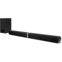
SC550SND - Soundbar SCHNEIDER - Free user manual and instructions
Find the device manual for free SC550SND SCHNEIDER in PDF.



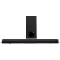
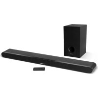
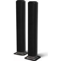
| Product type | Soundbar with wired subwoofer |
| Brand | Schneider |
| Model | SC550SND |
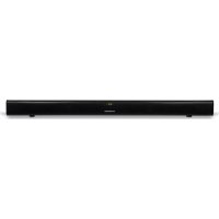
| Soundbar dimensions (W x D x H) | 818 x 60 x 60 mm |
| Subwoofer dimensions (W x D x H) | 150 x 220 x 320 mm |
| Approximate weight of soundbar | ~2.0 kg |
| Approximate weight of subwoofer | ~3.0 kg |
| Power supply | 220-240 V ~ 50-60 Hz |
| Power consumption | 30 W (soundbar) + 30 W (subwoofer) |
| Standby consumption | < 0.5 W |
| Output power | 2 x 15 W (soundbar) + subwoofer 30 W |
| Frequency response | 40 Hz - 20 kHz |
| Audio inputs | HDMI ARC, optical, auxiliary (3.5 mm), USB (service) |
| Wireless connectivity | Bluetooth 4.2 (A2DP, AVRCP) |
| Bluetooth range | ~10 m |
| Special features | Preset equalizer (News, Movie, Music), auto standby |
| Mounting | Horizontally on furniture or wall-mounted with included brackets |
| Remote control | Yes, with CR2025 battery included |
| Safety | Auto power off after 15 minutes of inactivity, surge protection |
| Maintenance | Clean with a dry, soft cloth. Do not use abrasive products. |
Frequently Asked Questions - SC550SND SCHNEIDER
User questions about SC550SND SCHNEIDER
0 question about this device. Answer the ones you know or ask your own.
Ask a new question about this device
Download the instructions for your Soundbar in PDF format for free! Find your manual SC550SND - SCHNEIDER and take your electronic device back in hand. On this page are published all the documents necessary for the use of your device. SC550SND by SCHNEIDER.
USER MANUAL SC550SND SCHNEIDER
natural_image
Two black electronic devices: a rectangular speaker and a cylindrical device with textured body (no visible text or symbols)BARRE DE SON 2.1 MODULABLE 2EN1 BLUETOOTH
- Getting started....18
- Overview of control....18
- Remote control....19
- The placement and mounting of the sound bar....20
- Connecting the subwoofer....22
- TV Connections....22
- Power connection....24
- General operation....24
- Bluetooth operation....25
- Specification....26
- Troubleshooting....27
Español
natural_image
Symbol of a trash bin crossed with no visible text or labels
natural_image
Line drawings of various household appliances including a cylindrical tube, a square button, a remote control unit, and a speaker (no text or symbols present)natural_image
Illustration of various electrical components including a coiled cable, plug, fuse, switch, and battery pack (no text or symbols)natural_image
Illustration of two types of electrical components: a battery pack and a rolled-up package (no text or symbols)Support mural Pied en caoutchouc
Mode d'emploi
natural_image
Two views of a cylindrical object with labeled parts (1 and 2), showing front and side views without any text or symbols.
natural_image
Simple line drawing of a hand pressing down on a device component with a downward arrow indicating motion (no text or symbols)
natural_image
Simple line drawing of a room setup with monitor, chairs, and a device labeled A (no text or symbols beyond label)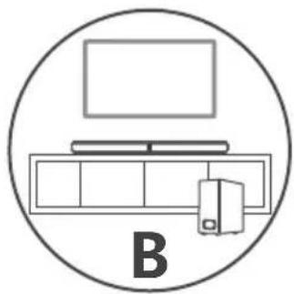
natural_image
Simple line drawing of a computer setup with monitor, tower, and keyboard inside a circle (no text or symbols)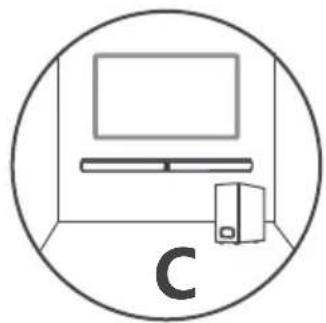
natural_image
Simple line drawing of a monitor setup inside a circle, with a tower and server nearby (no text or symbols)flowchart
graph TD
    A["Step 1: Internal components"] --> B["Step 2: Lock mechanism"]
    B --> C["Final assembled component"]
natural_image
Technical line drawing of a mechanical component with directional arrows indicating motion (no text or symbols)Montage mural (option C)
natural_image
Technical illustration showing two mechanical assembly steps with tool tips and arrows indicating movement (no text or symbols)natural_image
Illustration of hands using a hammer to measure a tool, with arrows indicating motion (no text or symbols)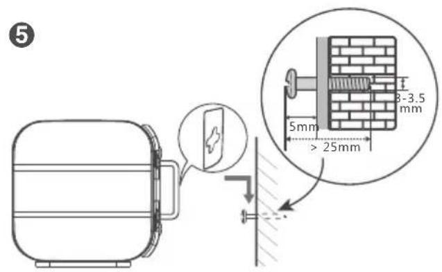
AVERTISSEMENT :
natural_image
Pure technical line drawing of a cylindrical mechanical part with no text or symbolsImportant safety instructions – please read carefully and keep for future reference

To reduce the risk of fire or electric shock, do not expose this product to water, rain or moisture. To prevent the risk of electric shock, do not remove the cover or back of this product. In case of product failure, only qualified personnel can repair. There are no user-serviceable parts inside.
CAUTION!
Dangerous tension inside the product! Do not open. Risk of electric shock! No parts can be repaired by the end-user. Only qualified personnel can repair and maintain this product.
If the electric cord is damaged, it must be replaced by the manufacturer or qualified after-sales personnel in order to avoid any danger.
The product must be installed in accordance with local laws.
Damaged batteries must be properly disposed. In order to protect the environment, please dispose the batteries properly, in accordance with local laws (information is available at your reseller).
Remote control battery (included) shall not be exposed to excessive heat (e.g. from sun or fire).
Note: Device operates in frequency range 2454-2483.5MHz is restricted to indoor use in France
Where to install the product
- Place the product on a straight, rigid and stable place. Do not place the product on a carpet.
- Do not place the product on top of another that may cause overheating (for example, a receiver or amplifier).
- Do not place anything underneath the product (for example, CDs or magazines).
Proper ventilation
- Place the product in a sufficiently-aerated place to avoid overheating. Allow at least 10cm spacing at the back and top of the product, and 5cm spacing on both sides to prevent overheating.
- Do not place items such as newspapers, tablecloth, curtains, in front of the ventilating openings.
Do not expose the product to high temperatures, moisture, water and dust.
- The apparatus shall not be exposed to dripping or splashing. No object filled with liquids, such as vases, shall be placed on the apparatus.
- Do not place other items close to this product that may damage it (for example, objects containing water or lightened candles).
- No naked flame sources, such as lighted candles, should be placed on the apparatus.
Electric supply
- Please unplug the product in case of prolonged non-use.
- If the supply cable is damaged, it must be replaced by the manufacturer or qualified after-sales personnel to avoid any danger.
- This product must be connected to an electrical supply 230V \~ 50Hz.
- The mains plug is used as the disconnect device, so the disconnect device shall remain readily operable
- Only use this product with the AC adaptor provided.
WARNING
- Do not ingest the battery, Chemical Burn Hazard (The remote control supplied with) this product contains a coin/button cell battery. If the coin/button cell battery is swallowed, it can cause severe internal burns in just 2 hours and can lead to death.
- Keep new and used batteries away from children.
- If the battery compartment does not close securely, stop using the product and keep it away from children.
- If you think batteries might have been swallowed or placed inside any part of the body, seek immediate medical attention.
EU declaration of conformity
Hereby, Admea declares that this Bluetooth sound bar is in compliance with the essential requirements and other provisions of the Radio Equipment Directive (RED) 2014/53/EU.
The full text of the EU declaration of conformity is available at the following internet address:
http://www.schneiderconsumer.com

Technical Specification:
Device: Sound bar
Operation Frequency: 2402 MHz to 2480MHz (BT 4.2)
RF Transmission Power: 2dBm W (power per channel)
Operation Environment: 0 – 40 Deg C
natural_image
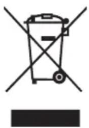
Symbol of a trash bin crossed with no text or numbers, representing waste sorting or disposal (no text present)- This logo set on the product means that the recycling of this apparatus comes within the framework of the directive 2012/19/EC of July 4, 2012 concerning the waste on electrical and electronic equipment (WEEE).
- The presence of dangerous substances in the electrical and electronic equipments can have potential consequences on the environment and human health in the cycle of reprocessing this product.
- Therefore, at the end of its lifetime, this product shall not be disposed with other non-recycled waste.
- As the end user, your role is of prime importance in the cycles of re-using, recycling, and other forms of valorization of this electrical and electronic equipment. Local authorities and resellers have set special procedures for the purpose of collecting and recycling this product.
- You have the obligation to use the selective waste collection systems put in place by your local authorities.
1. Getting started
What's included?
natural_image
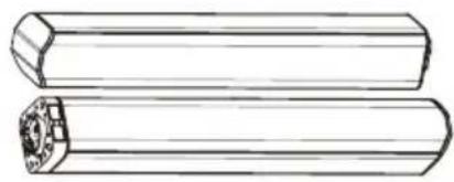
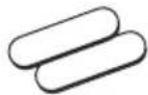
Technical line drawing of two cylindrical mechanical components with hexagonal ends and a flanged end (no text or symbols)Sound Bar
natural_image
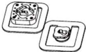
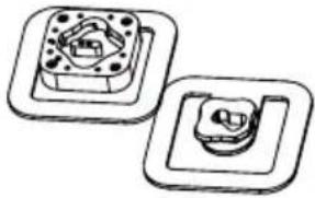
Two identical mechanical components with circular holes and square bases, shown in side view (no text or symbols)Stands
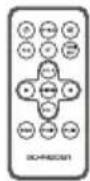
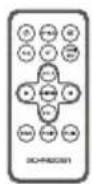
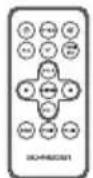
Remote Control
natural_image
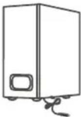
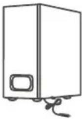
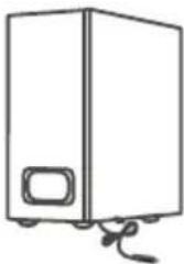
Simple line drawing of a rectangular electronic device with a side panel and cable (no text or symbols)Wired Subwoofer
natural_image
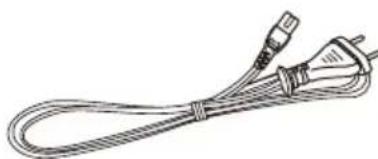
Line drawing of a cable with two connectors (no text or symbols)AC Power Cable
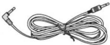
natural_image
Coiled audio cable with two leads (no text or symbols visible)3.5mm to 3.5mm audio cable
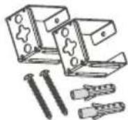
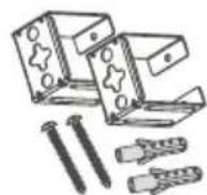
Wall Bracket
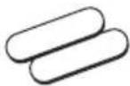
Rubber Feet

Instruction Manual
2. Overview of control
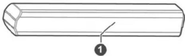
natural_image
Line drawing of a cylindrical object with a pointed tip and a numbered label (1) at the base, no text or symbols present.

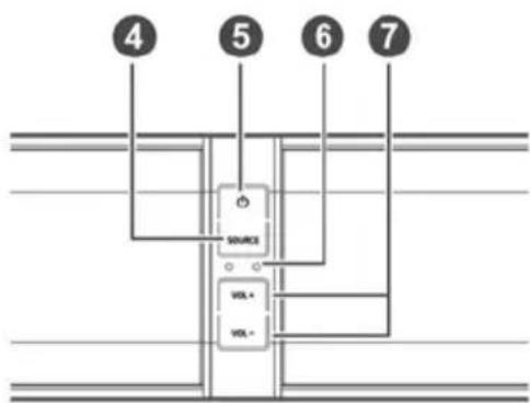
- Speakers
- Remote Control Sensor
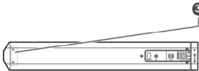
- Wall bracket screws
- SOURCE button
Select a source input from OPTICAL, AUX, BT, HDMI ARC
- ⏻ button
Switch on the Sound bar or switch to STANDBY mode
- LED Indicators
RED: STANDBY
GREEN: AUX
BLUE: BT(Bluetooth)
• ORANGE: OPTICAL
• ORANGE LIGHTS FLASH: HDMI ARC
- VOL+ / VOL- buttons
Increase / decrease the volume level.
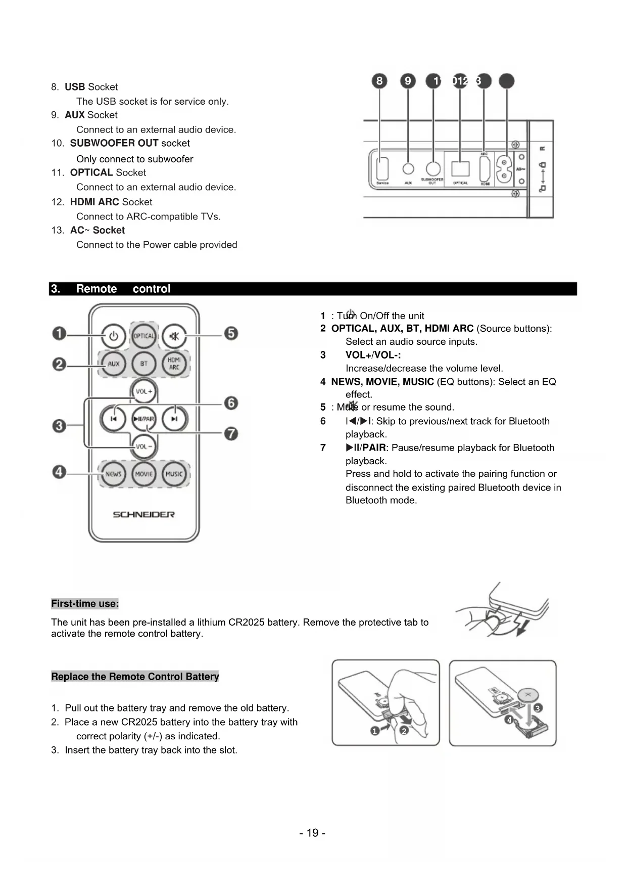
- USB Socket
The USB socket is for service only.
- AUX Socket
Connect to an external audio device.
- SUBWOOFER OUT socket
Only connect to subwoofer
- OPTICAL Socket
Connect to an external audio device.
- HDMI ARC Socket
Connect to ARC-compatible TVs.
- AC\~Socket
Connect to the Power cable provided

3. Remote control
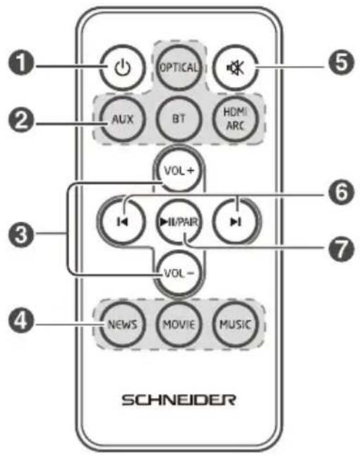
1 : Turn On/Off the unit
2 OPTICAL, AUX, BT, HDMI ARC (Source buttons): Select an audio source inputs.
3 VOL+/VOL-:
Increase/decrease the volume level.
4 NEWS, MOVIE, MUSIC (EQ buttons): Select an EQ effect.
5 : Mute or resume the sound.
6 I◄/►I: Skip to previous/next track for Bluetooth playback.
7 ▶II/PAIR: Pause/resume playback for Bluetooth playback.
Press and hold to activate the pairing function or disconnect the existing paired Bluetooth device in Bluetooth mode.
First-time use:
The unit has been pre-installed a lithium CR2025 battery. Remove the protective tab to activate the remote control battery.

natural_image
Diagram of a hand pressing a button with an arrow indicating motion (no text or symbols)Replace the Remote Control Battery
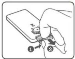
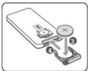
- Pull out the battery tray and remove the old battery.
- Place a new CR2025 battery into the battery tray with correct polarity (+/-) as indicated.
- Insert the battery tray back into the slot.
4. The placement and mounting of the sound bar
The placement of the sound bar
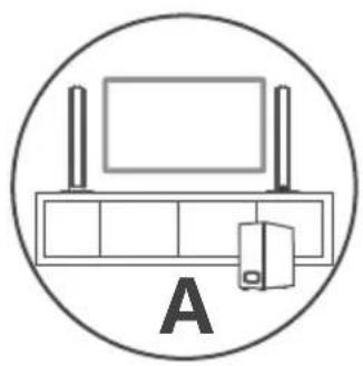
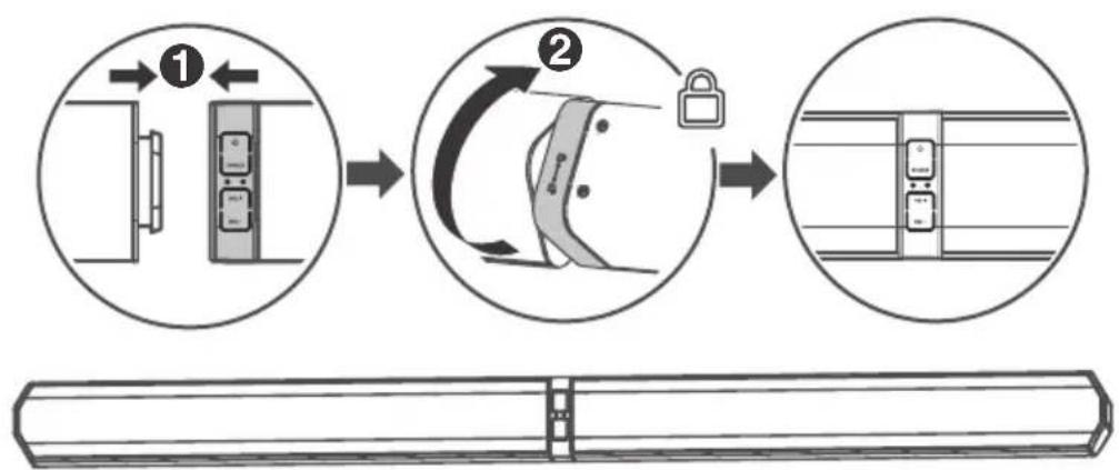
This unit can be used either a single sound bar or a 2-column speakers. You are suggested to put the unit with below options:
natural_image
Simple line drawing of a TV setup with monitor, tower, and monitor unit (no text or symbols)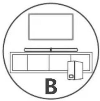
natural_image
Simple line drawing of a computer setup with monitor, tower, and monitor unit (no text or symbols)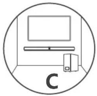
natural_image
Simple line drawing of a room with monitor, tower, and monitor unit (no text or symbols)Stand mounting the sound bar (option-A)

Horizontal mounting the sound bar (option-B)
flowchart
graph TD
    A["Step 1: Left-hand door opening"] --> B["Step 2: Lock lock and switch mechanism"]
    B --> C["Step 3: Closed door with lock and switch"]
Installing the Rubber Feet
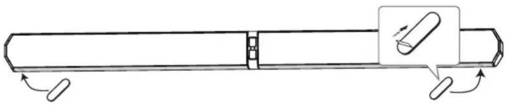
Ensure the surface is clean prior to sticking the rubber foot to the bottom of the unit.
- Turn the unit upside down.
- Remove the backing paper from the rubber foot.
- Stick the rubber foot to the bottom of the unit as shown in the illustration below.
natural_image
Technical line drawing of a mechanical component with directional arrows indicating motion (no text or symbols)Wall Mounting (option-C)
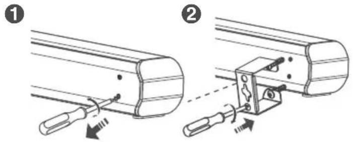
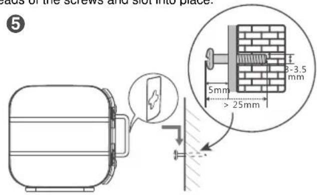
①. Remove the screws from the main unit.
②. Attach the wall brackets to the main unit with the screws removed from the main unit.
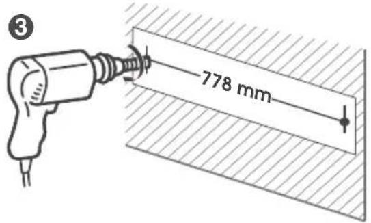
③. Drill 2 parallel holes ( 3-8 mm each according to wall type) in the wall. The distance between the holes should be 778 mm.
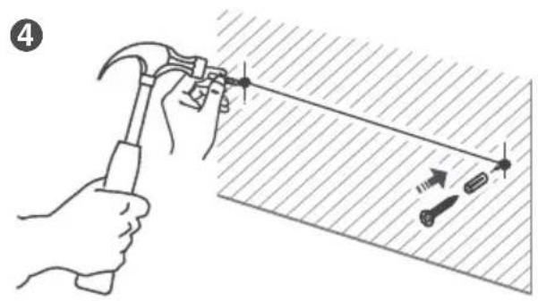
④. Firmly fix 1 dowel into each hole in the wall if necessary.
natural_image
Illustration of a hand using a hammer to apply a tool to a surface, with arrows indicating direction (no text or symbols)⑤. Leave a 5 mm gap between the wall and the screw's head. Lift the unit with the attached wall brackets over the heads of the screws and slot into place.
WARNING:
- Installation must be carried out by qualified personnel only. Incorrect assembly can result in severe personal injury and property damage (if you intend to install this product yourself, you must check for installations such as electrical wiring and plumbing that may be buried inside the wall). It is the installer's responsibility to verify that the wall will safely support the total load of the unit and wall brackets.
- Additional tools (not included) are required for the installation.
- Do not overtighten screws.
- Keep this instruction manual for future reference.
- Use an electronic stud finder to check the wall type before drilling and mounting.
5. Connecting the Subwoofer
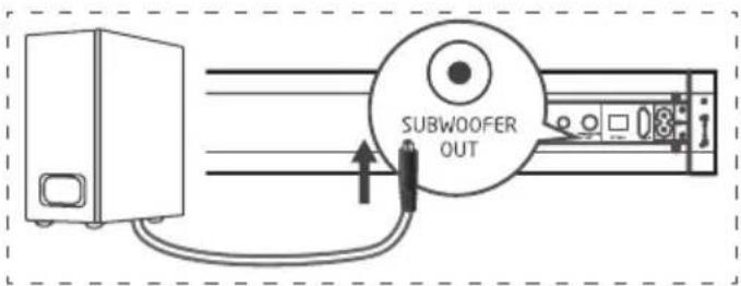
Connect the speaker cable from external subwoofer to the SUBWOOFER OUT socket on back of the sound bar.
WARNING:
The SUBWOOFER OUT socket on the sound bar can be connected to subwoofer only, do not connect it to a TV, DVD or Blu-ray player using the COAXIAL cable in case of any damages.
6. TV Connections
6.1 Connecting a TV, DVD, GAMES CONSOLE or SET-TOP BOX using the RCA-3.5mm audio cable (not supplied).
NOTE: Ensure that the TV PHONO connectors are audio OUTPUTS and not audio INPPUTS. If they are INPUTS then use connection 5.2
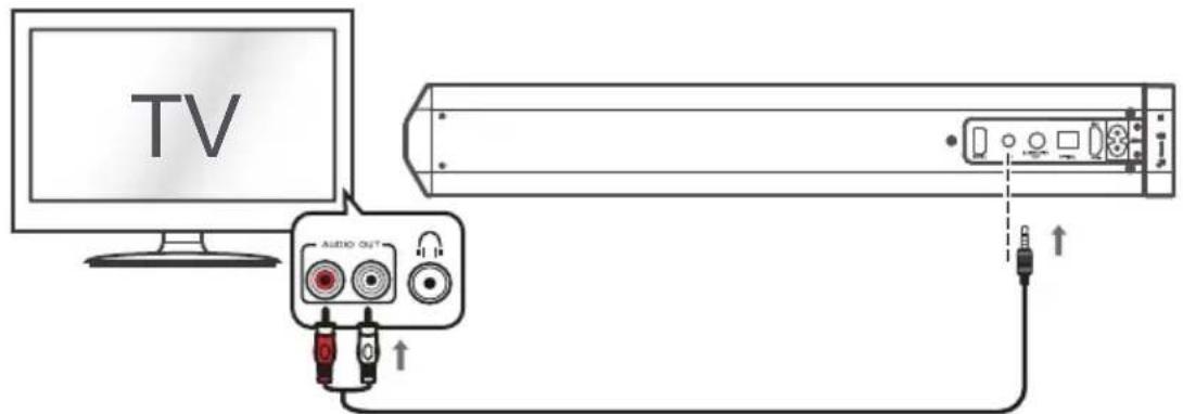
- Connect one end of the RCA cable to the TV, DVD or CONSOLE audio output RCA sockets.
- Connect the 3.5mm (small) end to the AUX socket on the back of the Sound bar.
NOTE: Take care to match the RED plug to the RED socket and the WHITE plug to the WHITE socket.
6.2 Connection to a TV using the 3.5mm-3.5mm audio cable provided.
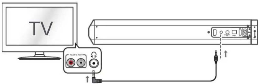
- Connect one end of the 3.5mm cable to the TV headphone 3.5mm audio output socket.
- Connect the other end of the cable to the AUX socket on the back of the sound bar.
NOTE: In some cases the Sound bar volume output is affected by the volume level on the TV. In this case adjust the TV volume to increase the audio output from the sound bar.
6.3 DIGITAL connection to a TV, DVD or Blu-ray player using the OPTICAL cable (not supplied).
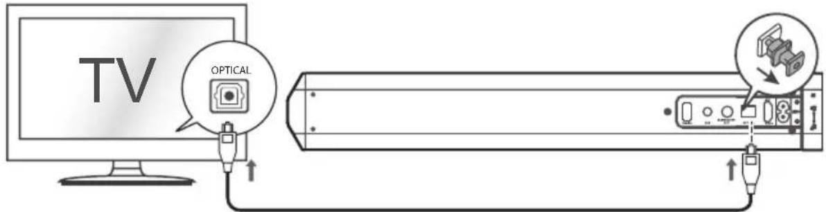
- Connect one end of the OPTICAL cable to the TV, DVD or Blu-ray OPTICAL audio output socket.
- Remove the protective cap of the OPTICAL socket, then connect the other end to the OPTICAL socket on the side of the Sound bar.
NOTE: You may need to activate PCM (Downmix) on your source device: TV, DVD or Blu-ray player.
6.4 Connection to a compatible TV HDMI ARC using a High-Speed HDMI cable that supports the ARC function (not supplied)
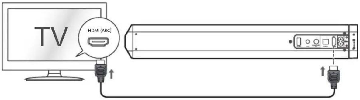
ARC (Audio Return Channel)
The ARC (Audio Return Channel) function allows you to send audio from your ARC- compliant TV to your sound bar through a single HDMI connection. To enjoy the ARC function, please ensure your TV is both HDMI-CEC and ARC compliant and set up accordingly. When correctly set up, you can use your TV remote control to adjust the volume output (VOL +/- and MUTE) of the sound bar.
- Connect one end of HDMI cable to the TV HDMI ARC output socket.
- Connect the other end of the cable to the HDMI ARC socket on the back of the sound bar.
- Press the SOURCE button repeatedly on the unit or press HDMI ARC buttons on the remote control to select HDMI ARC.
NOTE:
- Your TV must support the HDMI-CEC and ARC and the HDMI-CEC and ARC must be set to On.
- The setting method of HDMI-CEC and ARC may depend on the TV. For details about ARC function, please refer to the TV instruction manual.
- Ensure that you use an HDMI cables that can support the ARC function.
- HDMI-CEC will be called different names by different manufacturers, please refer to your TV instruction manual for details on setting up HDMI-CEC and ARC.
Important: ARC connection will only work with ARC-compatible TV. HDMI only-TVs are NOT compatible. Check your TV output. If it doesn't say "ARC", it means that it probably won't be compatible. Additionally, depending on the TV manufacturer, only one HDMI port may actually support ARC.
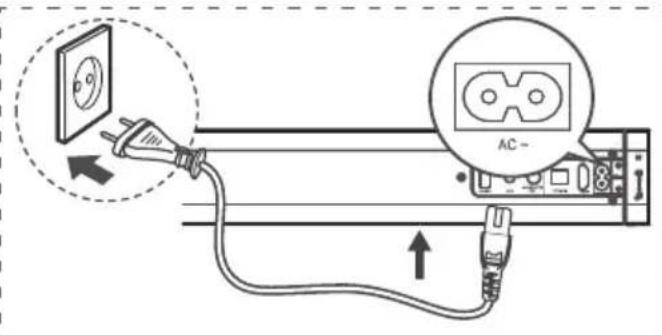
7. Power connection
- Ensure that the power supply voltage corresponds to the voltage printed on the back or the underside of the unit.
- Before connecting the AC power cord, ensure you have completed all other connections.
- Connect the mains cable to the AC\~ Socket of sound bar and then into a mains socket.
8. General operation
Status LED
| Operation | Description | LED Status |
| STANDBY Standby | RED | (solid) |
| SOURCE | AUX | GREEN (solid) |
| Bluetooth-ready for pairing BLUE (flash) | ||
| Bluetooth paired BLUE (solid) | ||
| OPTICAL | ORANGE (solid) | |
| HDMI ARC ORANGE (flash) | ||
| VOL+/- | Adjust sound volume Current input source color (blink twice) | |
| Maximum/Minimum volume Current input source color (flash three times) | ||
| MOVIE / MUSIC / NEWS | Select EQ effects | Current input source color (blink twice) |
| OK | Mute | Current input source color (flash) |
Standby mode
- Short-press the ⏻ button on the unit or the ⏻ button on the remote control to awake the unit from STANDBY mode.
- Short-press the ⏻ button on the unit or press the ⏻ button on the remote control to switch the unit back to STANDBY mode.
NOTE: As part of the power saving mode the unit will enter STANDBY mode automatically after 15 minutes (approx.) of no source input.
Switching inputs
Follow the below steps to switch inputs among: AUX, BT(Bluetooth), OPTICAL, HDMI ARC.
- Ensure the Sound bar is powered ON.
- Short-press the SOURCE button on the sound bar or the AUX, BT, OPTICAL, HDMI ARC buttons on the remote control until you see the corresponding color on the indicator.

natural_image
Pure technical line drawing of a cylindrical mechanical part with no text or symbolsSTANDBY: ....RED (solid)
AUX: ......GREEN (solid)
BLUETOOTH: ......BLUE (solid)
OPTICAL:......ORANGE (solid)
HDMI ARC:......ORANGE (flash)
Adjusting the volume level
Press the VOL+/VOL button on the unit or remote control repeatedly to increase or decrease the volume level.
Mute function
- Press the button on the remote control will temporarily silence the audio output.
- Press the ✗ or VOL+/VOL- button again to resume the audio output.
Sound effect presets
During palyback, press the MOVIE / MUSIC / NEWS button on the remote control to select EQ effects: MOVIE (recommended for viewing movies), MUSIC (recommended for listening to music), NEWS (recommended for listening to news)
9. Bluetooth operation
Pairing a Bluetooth device
Before you can use the sound bar with your phone or other Bluetooth capable device you will need to pair the device to the sound bar.
- Short-press the SOURCE button on the unit or the BT button on the remote control to select Bluetooth mode. The Blue indicator will flash slowly.
- Activate your Bluetooth device and select the mode name 'SC550SND' on your Bluetooth device list.
- If you cannot find the sound bar, press and hold the ▶II/PAIR button on the remote control until the Blue indicator flash rapidly and the unit prompts "Pairing". The system has entered pairing mode.
- Select "SC550SND" enter "0000" for the password if necessary. The unit will voice "Paired" and the Blue indicator will light up solidly.
- Play music from the connected Bluetooth device.
During playback, you can:
- Press ▶II/PAIR button pause or resume playback of the selected track on the audio device.
- Press b▶l to skip to last or next track.
To disconnect the Bluetooth function, you can:
- Switch to another function on the unit.
- Disable the function from your Bluetooth device. The Bluetooth device will be disconnected from the unit after the "Disconnected" voice prompt.
- Press and hold the ▶II/PAIR button on the remote control.
Bluetooth status table
| Operation | LED | Status | |
| Disconnected | BLUE | (flash | slowly) |
| Pairing BLUE (flash rapidly) | |||
| Connected | BLUE | (solid) | |
Note:
- The operation range of Bluetooth is approximately 10 meters (30 feet). Any obstacle in the path between devices may reduce this range.
- Only one Bluetooth device can be paired at a time.
-
Not all Bluetooth devices are compatible.
-
Specification
| Amplifier | |
| Power output 2X15W | |
| Frequency response 40Hz - 20kHz | |
| Input sensitivity 500 mV | |
| Main unit | |
| Power supply Input:220-240V ~ 50-60Hz | |
| Power consumption 30 W | |
| Standby power consumption | <0.5W |
| Full range speaker drivers | Impedance: 8 Ohm, 52mm (2") Frequency response: 40Hz - 20kHz |
| Dimensions | Horizontal: W818xD60xH60 mm Stand: W100XD426X100 mm |
| AC power cable length 1.5m | |
| Wired Subwoofer | |
| Power consumption 30W | |
| Impedance 6 Ohm, 101.6mm(4") | |
| Dimensions W150 x D220 x H320 mm | |
| Remote control | |
| Battery 1 x CR2025 | |
| Bluetooth | |
| Bluetooth compatibility EDR, A2DP, AVRCP | |
| Bluetooth version 4.2 | |
11. Troubleshooting
In the unlikely event of difficulties with your appliance please follow the trouble shooting guide below.
| PROBLEM | POSSIBLE SOLUTION |
| No Power | Ensure the mains plug is connected to a power supply, and is switched ON.Make sure there is power to the mains socket. |
| No Sound | When playing from the AUX input, Make sure the external source has the volume turned up and is playing a track.Make sure the volume is turned up.In AUX position if the sound bar is connected to a TV via the headphone output, make sure that you do not exceed 3⁄4 of the volume on the TV to eliminate the risk of saturation.When playing from OPTICAL/HDMI ARC input, the OPTICAL/HDMI ARC lights flashes quickly, You may need to set the source DIGITAL output to PCM, LPCM, PCM 2Ch stereo or PCM downmix, since the device has no Dolby decoder.When palying from the HDMI ARC input, ARC connection will only work with ARC-compatible TV. HDMI only-TV are NOT compatible. Check your TV output. If it doesn't say “ARC”, it means that it probably won't be compatible. Additionally, depending on the TV manufacturer, only one HDMI port may actually support ARC.When playing from the AUX input, Make sure the other device's connection is output not InputBluetooth device not paired. Refer to “Bluetooth operation”. |
| No response from the unit | Unplug the power cable for 1 minute then plug back in again. |
| Remote control does not work | Reduce the distance between the remote and main unit.Check the batteries are installed correctly.Replace the batteries.Aim the remote directly at the Sound bar |
| Unit powers off after 15 minutes | This unit is designed to enter STANDBY mode automatically after 15 MINUTES of inactivity. Press the button on the unit or button on the remote control to wake the unit. |
After-sales service
ADMEA/LOGISAV
natural_image
Two cylindrical mechanical components with hexagonal ends and a small circular end (no text or symbols)Barra de sonido
natural_image
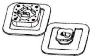
Two mechanical component diagrams showing mounting flanges and a central housing (no text or symbols)Soportes
Mando a distancia
natural_image
Simple line drawing of a desktop computer with a speaker and cable (no text or symbols)natural_image
Line drawing of a cable with two connectors (no text or symbols)natural_image
Coiled audio cable with two connectors (no text or symbols visible)natural_image
Line drawing of a cylindrical object with a pointed tip and labeled point 1 (no text or symbols on the object itself)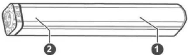

8. Toma USB
natural_image
Diagram of a hand pressing a button with a downward arrow indicating motion (no text or symbols)
flowchart
graph TD
    A["Step 1: Device with bidirectional movement"] --> B["Step 2: Lock mechanism with curved motion"]
    B --> C["Final state: Panel with two rectangular blocks"]
natural_image
Technical line drawing of a mechanical component with directional arrows indicating motion (no text or symbols)natural_image
Illustration of a hand using a hammer to measure a tool on a surface, with arrows indicating motion (no text or symbols)
ADVERTENCIA:
natural_image
Pure technical line drawing of a cylindrical mechanical part with no text or symbolsnatural_image
Symbol of a trash bin crossed out by two crossed lines, with a solid black rectangle below (no text or labels)natural_image
Line drawing of two cylindrical mechanical components with hexagonal ends and a central hub (no text or symbols)Soundbar
natural_image
Two identical mechanical components with circular holes and a central housing, shown in side view (no text or symbols)Suportes
Controlo remoto
natural_image
Simple line drawing of a computer monitor with a cable, no text or symbols presentSubwoofer com fio
natural_image
Line drawing of a cable with a plug and connector (no text or symbols)natural_image
Coiled audio cable with two leads, no text or symbols visibleCabo á udio de 3,5 mm a 3,5 mm
Suporte de parede
Pé s de borracha
natural_image
Line drawing of a cylindrical object with a pointed tip and labeled point 1 (no text or symbols on the object itself)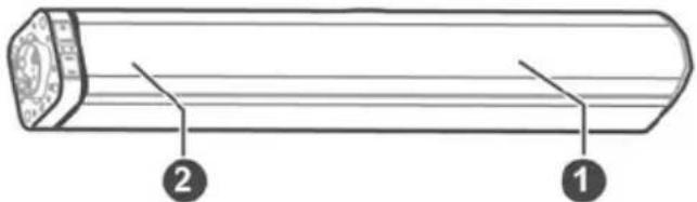
natural_image
Diagram of a device rear panel with an attached cable and indicator lights (no text or symbols)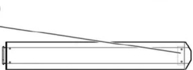
natural_image
Pure technical line drawing of a mechanical component or tool (no text or symbols)- Tomada USB
natural_image
Diagram of a hand pressing a button with a downward arrow indicating motion (no text or symbols)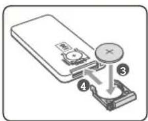
natural_image
Technical line drawing of a mechanical component with directional arrows indicating motion (no text or symbols)natural_image
Technical illustration showing two mechanical assembly steps: tool insertion and disassembly (no text or symbols)natural_image
Illustration of hands using a hammer to apply a tool to a surface, with arrows indicating motion (no text or symbols)AVISO:
6. Ligações TV
8. Operações gerais
LED de estado
natural_image
Pure technical line drawing of a cylindrical mechanical part with no text or symbolsEM ESPERA: ......VERMELHO (fixo)

- BARRE DE SON 2.1 MODULABLE 2EN1 BLUETOOTH
- Español
- Montage mural (option C)
- AVERTISSEMENT :
- Important safety instructions – please read carefully and keep for future reference
- CAUTION!
- Where to install the product
- Proper ventilation
- Do not expose the product to high temperatures, moisture, water and dust.
- Electric supply
- WARNING
- EU declaration of conformity
- Technical Specification:
- Getting started
- Overview of control
- Remote control
- First-time use:
- Replace the Remote Control Battery
- The placement and mounting of the sound bar
- The placement of the sound bar
- Installing the Rubber Feet
- Wall Mounting (option-C)
- WARNING:
- Connecting the Subwoofer
- TV Connections
- Connecting a TV, DVD, GAMES CONSOLE or SET-TOP BOX using the RCA-3.5mm audio cable (not supplied).
- Connection to a TV using the 3.5mm-3.5mm audio cable provided.
- DIGITAL connection to a TV, DVD or Blu-ray player using the OPTICAL cable (not supplied).
- Connection to a compatible TV HDMI ARC using a High-Speed HDMI cable that supports the ARC function (not supplied)
- ARC (Audio Return Channel)
- NOTE:
- Power connection
- General operation
- Standby mode
- Switching inputs
- Adjusting the volume level
- Mute function
- Sound effect presets
- Bluetooth operation
- Pairing a Bluetooth device
- During playback, you can:
- To disconnect the Bluetooth function, you can:
- Troubleshooting
- After-sales service
- Toma USB
- ADVERTENCIA:
- AVISO:
- Ligações TV
- Operações gerais
Brand : SCHNEIDER
Model : SC550SND
Category : Soundbar