
BHG400SS - Cooker BAUMATIC - Free user manual and instructions
Find the device manual for free BHG400SS BAUMATIC in PDF.

| Product Type | Built-in gas hob |
| Brand | Baumatic |
| Model | BHG400SS |
| Number of burners | 3 (1 rapid, 1 auxiliary, 1 dual crown) |
| Compatible gas type | Natural gas (G20/G25) or liquefied gas (G30/G31) |
| Power supply | 220-240 V ~ 50/60 Hz |
| Total thermal power | 8 kW (rapid 3 kW, auxiliary 1 kW, dual 4 kW) |
| Ignition | Electronic via electrodes |
| Flame adjustment | 5 levels with continuous variation |
| Timer | Independently programmable for each burner (0 to 9 hours) |
| Slow cooking function | Automatic on/off cycle (duty cycle) |
| Keyboard lock | Yes, KL key |
| Safety | Flame detection by ionization, automatic shutdown in case of extinction, electronic self-diagnosis, residual heat indication (H) |
| Table material | Glass and stainless steel |
| Maintenance | Clean with non-abrasive products, the burners with boiling water and detergent. Do not use steam cleaners. |
| Installation | By a professional, gas and electrical connection according to current standards |
| Adaptation to gas type | Interchangeable injectors, electronic adjustment of minimum flow |
| Gas consumption (G20) | Rapid 286 l/h, auxiliary 95 l/h, dual 381 l/h (total 762 l/h) |
| Error codes | Display of codes (B, F, Ft00 to Ft0E, etc.) for diagnosis |
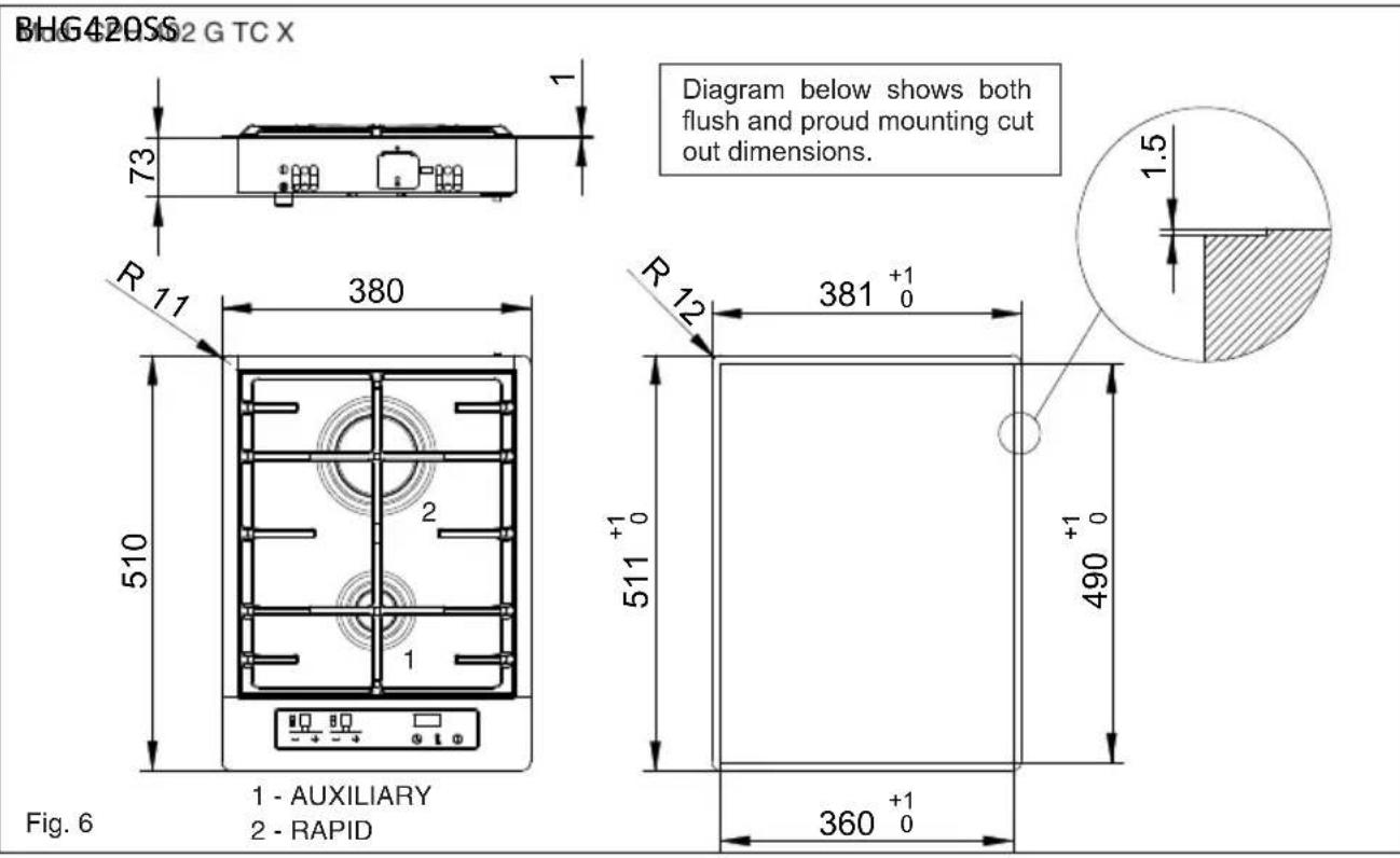
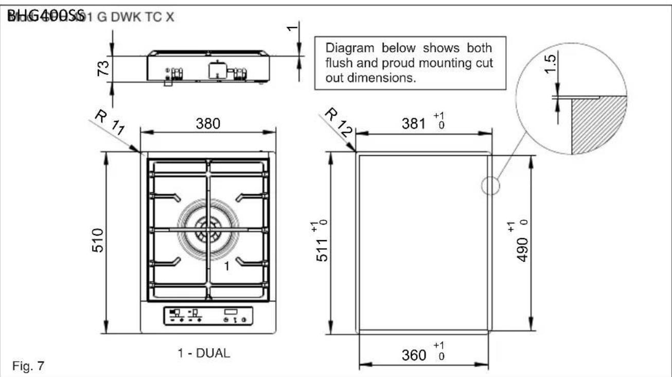
| Cutout dimensions | Refer to figures 6-9 of the manual |
Frequently Asked Questions - BHG400SS BAUMATIC
User questions about BHG400SS BAUMATIC
0 question about this device. Answer the ones you know or ask your own.
Ask a new question about this device
Download the instructions for your Cooker in PDF format for free! Find your manual BHG400SS - BAUMATIC and take your electronic device back in hand. On this page are published all the documents necessary for the use of your device. BHG400SS by BAUMATIC.
USER MANUAL BHG400SS BAUMATIC
| LIVELLO IMPOSTATO | 1 2 | 3 4 5 | |||
| TEMPO DI SPEGNIMENTO | 10 Sec. | 20 Sec. | 30 Sec. | 40 Sec. | 50 Sec. |
| TEMPO DI ACCENSIONE | 50 Sec. | 40 Sec. | 30 Sec. | 20 Sec. | 10 Sec. |
We thank you and congratulate you on your choice.
This new carefully designed product, manufactured with the highest quality materials, has been carefully tested to satisfy all your cooking demands.
We would therefore request you to read and follow these easy instructions which will allow you to obtain excellent results right from the start.
May we wish you all the very best with your modern appliance!
THE MANUFACTURER
Index
Instructionsfor use 16
Installation 16
Use 16
Maintenance 19
Instructions for the installer 20
Installation 20
Gas connection 22
Electrical connection 22
User characteristics 25
THIS APPLIANCE IS CONCEIVED FOR DOMESTIC USE ONLY.
THE MANUFACTURER SHALL NOT IN ANY WAY BE HELD RESPONSIBLE FOR WHATEVER INJURIES OR DAMAGES ARE CAUSED BY INCORRECT INSTALLATION OR BY UNSUITABLE, WRONG OR ABSURD USE. THIS APPLIANCE IS NOT INTENDED FOR USE BY PERSONS (INCLUDING CHILDREN) WITH REDUCED PHYSICAL, SENSORY OR MENTAL CAPABILITIES, OR LACK OF

Italiano
GB
English
FR
Français
DE
Deutsch
ES
Espanol
PT
Portugues
EXPERIENCE AND KNOWLEDGE, UNLESS THEY HAVE BEEN GIVEN SUPERVISION OR INSTRUCTION CONCERNING USE OF THE APPLIANCE BY A PERSON RESPONSIBLE FOR THEIR SAFETY.
CHILDREN SHOULD BE SUPERVISED TO ENSURE THAT THEY DO NOT PLAY WITH THE APPLIANCE.
Cation: This appliance, its components and the surrounding area will become hot during use, and retain heat after use.
Instructions for use
Installation
All the operations concerned with the installation (electrical and gas connections, adaptation to type of gas, necessary adjustments, etc.) must be carried out by qualified technicians, in terms with the standards in force. For specific instructions, kindly read the part reserved for the installation technician.
Use
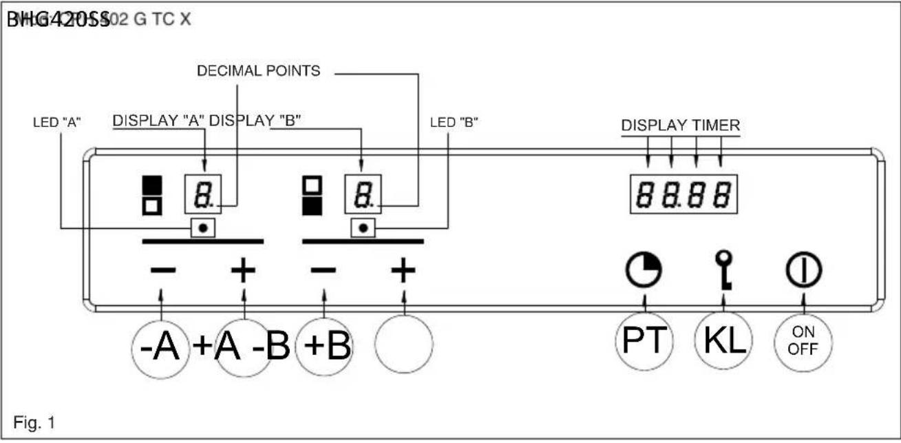
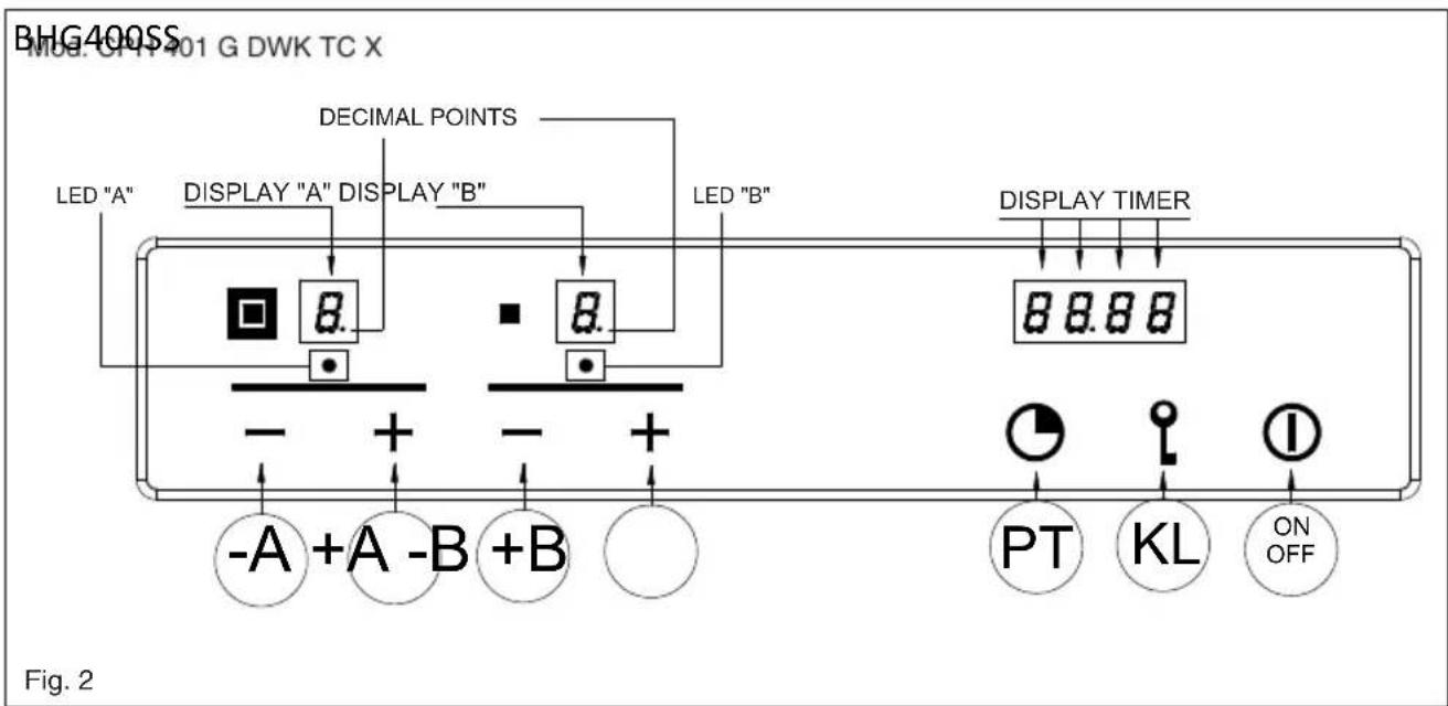
Standby mode (Fig. 1-2)
When the device is turned on, it performs a brief self-test and calibrates the touch-pad (all displays and LEDs turn on for several seconds). At the end, the display will be completely off. In this mode, the device can be turned on by simply pressing the ON/OFF key.
Turning on the Cooking Surface
To turn on the device, you must hold down the ON/OFF key for at least 2 seconds. The device will turn on and the burner displays will display level zero, which corresponds to burner off.
Turning on a burner
To turn on a burner, press the relative + and - keys on the control panel. The keys must be pressed simultaneously and held down for at least 1 second. When the burner turns on, the burner will be set to the average flow and the relative display will show level 3.
Each burner whose timer has not been programmed will automatically turn off after 4 hours of continuous operation.
The ignition of the burner is also indicated by the led under the relative display, which remains active the whole time the burner is lit.
Adjusting the flame level of a burner
To increase the flow to a burner that is on, press the + key and to decrease the flow, press the - key. For a continuous change in the flow level, just hold down the + or - key and release it at the desired level. The flow level varies from 1 to 5.
Turning off a burner
To turn a burner off, press the + and - keys simultaneously for a brief instant.
Turning off all the burners
To turn all the burners off at the same time, briefly press the ON/OFF key; this puts the device in standby mode.
Programming the burner switch-off time
It is possible to independently programme each burner to switch off automatically after a specific length of time. To programme the timer of a burner, press the PT key. The word Time will appear on the time display. Now press the + or - key of the burner to be timed. The word Time will disappear and be replaced by the indication 0.00. The burner selected is identified by the relative Led. The flashing digit to the left of the dot indicates the hours, while those to the right indicate the minutes. By pressing the + or - keys of the burner selected it is possible to increase or decrease the operating hours from 0 to 9. Keeping the + or - keys pressed the change in the number of hours will take place continuously.
To specify the number of minutes, press the PT key again. The digits to the right of the dot will start flashing. Set the minutes in the same way as indicated for the hours.
When programming the time it is possible to zero the current setting at any time by pressing the + and - keys. A time equal to zero deactivates the burner timer. To confirm the time shown on the display, press the PT button. At this point, only the indicators of the burners with the timer active continue to flash.
The time remaining until switch-off is indicated on the display, with a "t" in front of the time (e.g.: t0.12). If no button is pressed for more than 10 seconds during programming, the programming procedure is interrupted automatically and the main display returns. Any settings being changed on the burner selected will not be lost and the relative time is active.
The timer can be programmed both with the burner switched off or lit, and the counter will start immediately after the time programmed has been confirmed. When the countdown ends, the timed burner will turn off and a sequence of beeps will sound for 30 seconds. This sequence can be interrupted by pressing the PT key.
If the user switches off a burner, the relative timer is deactivated.
Note for gas model (2 burner)
If both burners are programmed at the same time, the timer display will show the count for the burner that will switch off first and the Led related to this burner will flash faster than the other one.
Note for the Dual model (single burner)
This model can only be programmed with keys -B and +B. If both rings are lit, the timer will e valid for both. If only the inner ring is lit the timer will be valid for the inner ring only.
Regulating the clock
Following interruptions to the power supply, it is necessary to set the time displayed by the clock inside the hob on the device. To regulate the clock
it is necessary to press the PT and KL keys at the same time, for at least 3 seconds.
The flashing digit to the left of the dot indicates the hours, while those to the right indicate the minutes. It is possible to increase or decrease the hours using keys +A or -A and by keeping keys +A or -A pressed the change in the number of hours takes place continuously.
To regulate the minutes, press the PT key again. The digits to the right of the dot will start flashing. Now change the minutes in the same way as indicated for the hours. Press the PT key to memorise the time programmed.
Releasing the burner
When a burner is locked the relative display shows the letter "B". The burner is released by pressing the -A and KL keys together constantly for at least 2 seconds. When released, the burners are reset to level 0, ready to be lit again.
N.B: If the release procedure is repeated 5 times in a row during a 15 minute time span, the device will indicate Ft06 and will accept no further request for release for another 15 minutes.
Locking the control panel
This is activated by pressing the KL key for at least 2 seconds. All burner levels will remain stable. The control panel locked status occurs when the decimal points on the display of the capacity level related to each burner light up. While the control panel is locked it is no longer possible to change the levels of the burners or change the timer settings, but it is possible to switch off the hob by pressing the ON/OFF button.
It is not possible to release a locked burner when the control panel lock is active. It will be therefore necessary to release the control panel before activating the burner release procedure.
Releasing the control panel
The control panel is released by pressing the KL and +A keys for at least 2 seconds. The control panel is released when the flame level points on the display go out.
Residual Heat
When a burner goes out, the relative display shows an "H" to indicate that the temperature of that burner is still high and the relative LED near the timer display remains on.
The "H" symbol and the LED turn off when the temperature of the relative burner is cool.
Special slow cooking (Duty cycle)
This function turns any cook top burner on and off is the sequence shown in the table.
| LEVEL SET. 1 2 3 | 4 5 | ||||
| TURN-OFF TIME | 10 Sec. | 20 Sec. | 30 Sec. | 40 Sec. | 50 Sec. |
| TURN-ON TIME | 50 Sec. | 40 Sec. | 30 Sec. | 20 Sec. | 10 Sec. |
The function is activated by pressing the + key of the burner you want to apply it to, and the PT key (the burner involved must be off when this function is activated).
The burner turns on at level 3 and, at that time, you can set the level to apply the function to by pressing the + and - keys.
If, for example, you set the value to level 1, the burner will remain on for 50 seconds, then it will turn off for 10 seconds and repeat this cycle until you turn the burner off.
If the user does not intervene, the hob switches off automatically after 60 minutes. When this function is active, the display of the burner on which it is active flashes.

N.B
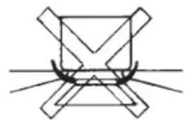
- We recommend the use of pots and pans with a diameter matching that of the burner, thus preventing the flame from escaping from the bottom part and surrounding the pot (Fig. 3);
- do not leave any empty pots or pans on the fire;
When cooking is finished, it is also a good norm to close the main gas pipe tap and/or cylinder.
GAS
dual 20-32
fast 20-24
auxiliary* 010-14
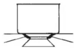
Fig. 3
Maintenance
Prior to any operation, disconnect the appliance from the electrical system. For long-life to the equipment, a general cleaning operation must take place periodically, bearing in mind the following:
- the glass and steel parts must be cleaned with suitable non-abrasive or corrosive products (found on the market). Avoid chlorine-base products (bleach, etc.);
- avoid leaving acid or alkaline substances on the working area (vinegar, salt, lemonjuice, etc.);
- the wall baffle and the small covers (mobile parts of the burner) must be washed frequently with boiling water and detergent, taking care to remove every possible encrustation. Dry carefully and check that none of the burner holes is fully or partially clogged; check periodically the state of conservation of the flexible gas feed pipe. In case of leakage, call immediately the qualified technicians for its replacement.
DO NOT USE STEAM CLEANERS
Instructions for the installer
GB
Installation
This appliance is not provided with a combustion product discharge. It is recommended that it be installed in sufficient aerated places, in terms of the laws in force.
The quantity of air which is necessary for combustion must not be below 2.0m^3 /h for each kW of installed power. See table of burner power.
Positioning (Fig. 4)
The cook top is designed to be built in to a work surface as shown in the figure.
Before installing the cook top, install the gasket seal around the entire perimeter of the hole where it will be inserted.
The dimensions of the hole are shown in figures 6-7-8-9. For flush mounting, the perimeter of the hole must be lowered by a depth of 1.5mm
The hole does not need to be milled for Semifilotop models.
The cook top can be installed on different materials such as brickwork, steel, marble, conglomerates, synthetics, wood and wood covered with plastic laminates, so long as resistant to a temperature of 90^ .
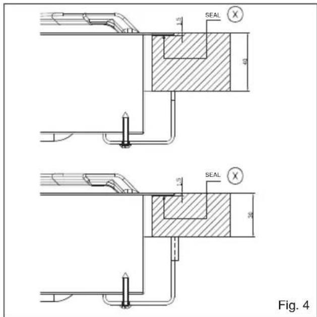
Fig. 5
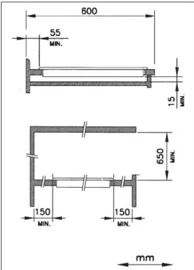
A panel made of wood or other insulating material must be installed under the cook top at a distance of at least 15mm from the surface.

Gas connection (Fig. 8)
The connection to a gas tank or gas line must be made by a qualified person in conformity to current updated gas safety and building standards after making sure that the cook top is prepared for the type of gas available. If not, see: "Adapting to different types of gas". Also check that the feed pressure falls within the values shown in the table: "User characteristics".
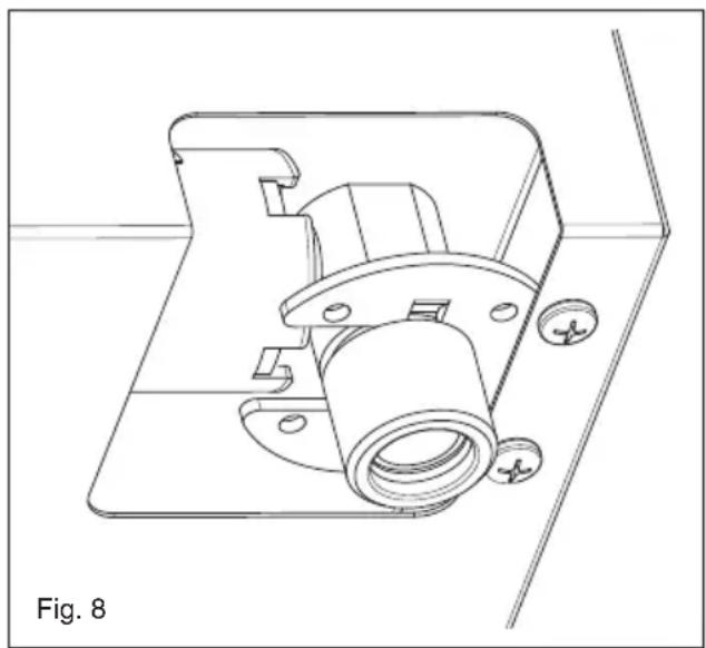
Metal rigid/semi-rigid hook-ups
Make the hook-up with metal fittings and pipes (even flexible hoses) so as not to stress the components inside the cook top.
Note: - After installation, use soapy water to check the perfect seal of the entire connection system.
Important note: make the connection using only metal fittings and pipes (flexible, continuous-wall steel hoses or rigid copper or steel tubing) and in such a way that its entire length can be inspected.
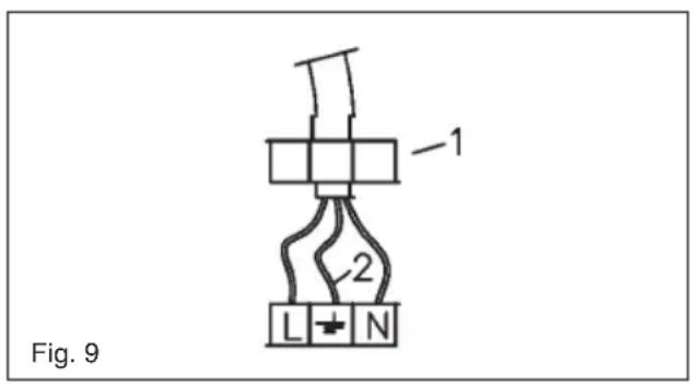
Electrical connection (Fig. 9)
The installer must be qualified and is responsible for correct electrical connections and following safety standards.
Prior to carrying out the electrical connection, please ensure that:
- The supply voltage marked on the rating plate corresponds with your mains supply.
- that the appliance is fitted with an efficient earth connection, following the standards and law provisions in force.
The earth connectionis compulsory in terms of the law.
Should there be no cable and/or plug on the equipment, use suitable absorption material for the working temperature as well, as indicated on the matrix plate. Under no circumstance must the cable reach a temperature above 50^ of the ambient temperature. If connecting directly to the mains power supply, fit a multi-pole switch of a suitable size for the rated capacity with a clearance distance which completely disconnects the power line under overvoltage category III conditions, consistently with the rules of installation (the yellow/green earth wire must not be interrupted). The plug or omnipolar switch must be easily reached on the installed equipment.
Adaptation to various types of gas (Fig. 10)
Should the appliance be pre-set for a different type of gas than available, proceed as follows:
- replace the injector (Fig. 7) with the corresponding type of gas to be used (see table "User characteristics");
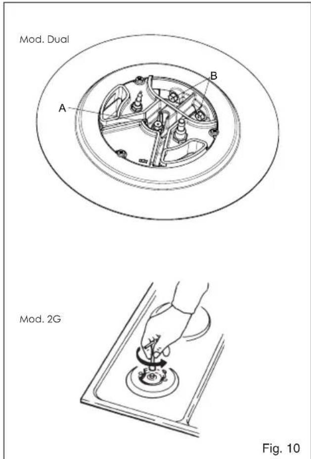
will show the indication - if the minimum level programmed corresponds with the factory setting, and the indication will change or v in flashing mode, indicating a higher or lower capacity than that programmed. The procedure ends by pressing the PT key. The minimum capacity levels will then be acquired and memorised by the device, and will be used in the normal use of the hob.
Selecting the type of fuel gas
You can configure the cook top to work with different gases (see table 1). To select the fuel gas to use, the cook top must be on with all the burners off. Just press the burner A, burner B and P- keys together for at least 2 seconds. When the fuel gas selection procedure starts, the burner level display turns off and the timer display shows "2020", "3029", "2525" or "2010", depending on the current configuration in use. It is possible to select the desired setting with the A+ and A- keys. To end the procedure, you must press the PT key.
Using this function deletes any turn-off times that may have been programmed for the burners.
Electronic self-test
The electronic parts are continuously checking their status. If there are any hardware or board problems that could affect the end-user's safety, the cook top goes into a "safe" mode which closes the solenoid valves and displays a code relative to failure.
Minimum burner capacity regulation procedure
The procedure for acquiring the minimum capacities allows the operator to change the minimum capacity programmed, adapting every burner to the characteristics of the gas distribution network to which the hob is connected.
The procedure is activated by pressing the +A and -A keys together with the +B key constantly for 3 seconds, with the burners all switched off.
The activation of the regulation procedure is indicated on the display with the word "MIN". It is now possible to select the burner to regulate using the respective + and - keys. After pressing one of the keys, the burner selected will come on at minimum level and it will be possible to increase or reduce the capacity to the minimum level using the using the + and - keys for this burner. During the display regulation procedure, the flame display levels

| Error displayed | Problem type Possible | cause Possible solution | |
| B Single burner locked | No gas | Restore the gas and unlock the burners | |
| Ionization electrode dirty or not hit by the flame | Clean or reposition the electrode and unlock the burners | ||
| The cook top is not grounded | Check the cables and unlock the burners | ||
| F | Parasite flame/flame detection circuit anomaly on the single burner | Ionization electrode wired incorrectly Check the wiring | |
| Failure at the circuit Replace the device | |||
| Flt00 | Main valve control circuit anomaly | Failure at the circuit Replace the device | |
| Flt01 | Anomaly circuit voltage of reference | Failure at the circuit Replace the device | |
| Flt02 Watch dog circuit anomaly Failure at the circuit Replace the device | |||
| Flt03 Microcontroller door anomaly Failure at the circuit Replace the device | |||
| Flt04 Eeprom anomaly Failure at the circuit Replace the device | |||
| Flt05 Pilot valve circuit anomaly Failure at the circuit Replace the device | |||
| Flt06 | Limit of 5 unlocks in 15 minutes exceeded | The burners have been unlocked 5 times in 15 minutes | Wait 15 minutes before unlocking the burners |
| Flt08 Power supply circuit anomaly Failure at the circuit Replace the device | |||
| Flt09 | Generic anomaly | Power was cut to the device when another type of failure had occurred previously | Unlock the burners |
| Resonator anomaly Failure at the circuit Replace the device | |||
| Flt0A All burners locked | No gas | Restore the gas and unlock the burners | |
| Ionization electrodes dirty or not hit by the flame | Clean or reposition the electrodes and unlock the burners | ||
| The cook top is not grounded | Check the cables and unlock the burners | ||
| Gas is leaking from one valve that caused the unwanted lighting of a second burner while the first was being lit. This problem is caused by flame in the second burner for more than 10 seconds. | Replace the defective valve | ||
| Flt0[ | Communication errors in the control logic | Failure at the circuit Replace the device | |
| Flt0E | Error in the control of the keypad | A mechanical deformation could have compromised the support of the keypad by the glass | Wait several seconds for the keypad to recalibrate. If the error persists, turn the power off and on. If the error still persists, replace the device. |
| Flt1E | Control panel hardware error Circuit failure | Check that the control panel board is correctly inserted into the connector. Replace the device | |
| Flt2E | Control panel hardware error Circuit failure | Check that the control panel board is correctly inserted into the connector. Replace the device | |
Table 1.
| USER CHARACTERISTICS | ||||
| GAS BURNERS | ||||
| FEEDTYPE PRESSURE mbarNORM. | BURNER | Ø INJECTORS1/100 | THERMALCAPACITY | CONSUMPTION |
| Natural gas G20 20("2020" in display) | fast 129 3000 286auxiliary 77 1000 95dual 71A-95B 4000 381 | £ | ||
| Liquefiedgas (LPG) G30/G31 28-30/37("3029" in display) | fast 87 3000 218auxiliary 50 1000 73dual 46A-65B 4000 291 | £ | ||
| Natural gas G25 25("2525" in display) | fast 132 3000 332auxiliary 80 1000 111dual 71A-100B 4000 443 | £ | ||
| Natural gas G20 10("2010" in display) | fast 155 3000 286auxiliary 92 1000 95dual 80A-143B 4000 381 | £ | ||

SERVIZIO ASSISTENZA TECNICA:0331-723318
Chere clientele,
CE PRODUIT EST CONCU EXCLUSIVEMENT POUR USAGE DOMESTIQUE.
LE CONSTRUCTEUR DÉCLINE TOUTERESPONSABILITÉ POURDOMMAGESET BLESSURES CAUSES PAR UNEINSTALLATION INCORRECTE OU PAR UNUSAGE IMPROPRE, ERRONÉ OU ABSURDE.L'APPAREIL NE DOIT PAS ÉTRE UTILISÉPAR DES PERSONNES (ENFANTS INCLUS)DISPOSANT DE CAPACITÉS PHYSIQUES,SENSORIELLES OU MENTALES RÉDUITES,

Italiano

English

Français

Deutsch

Espanol

Portugues
OU PAR DES PERSONNES N'AYANT PAS L'EXPERIENCE OU LES CONNAISSANCES REQUISES, Si CE N'EST SOUS LA SURVEILLANCE D'UNE PERSONNE RESPONSABLE DE LEUR SECURITE OU APRES AVOIR REÇU DE CELLE-CI LES INSTRUCTIONS RELATIVES À L'UTILISATION DE L'APPAREIL. LES ENFANTS DOIVENT ÉTRE SURVEILLÉS, AFIN DE S'ASSURER QU'ILS NE JOUENT PAS AVEC L'APPAREIL.

Notice d'emploi
Installation
| NIVEL PROGRAMADO | 1 2 | 3 4 5 | |||
| TEMPO DE APAGAMENTO | 10 Sec. | 20 Sec. | 30 Sec. | 40 Sec. | 50 Sec. |
| TEMPO DE ACENDIMENO | 50 Sec. | 40 Sec. | 30 Sec. | 20 Sec. | 10 Sec. |
Customer Care Telephone
(0118) 933 6911
Customer Care Fax
(0118) 986 9124
Spares Telephone
(01235)437244
Advice Line Telephone
(0118) 933 6933
E-mail:
sales@baumatic.co.uk
customercare@baumatic.co.uk
spares@baumatic.co.uk
technical@baumatic.co.uk
Website:
www.baumatic.co.uk
Facebook:
www.facebook.com/baumatic.uk
Republic of Ireland
Service Telephone
1-890 812 724
Spares Telephone
091756771
Czech Republic/ Slovakia
Baumatic s.r.o.
Lipova 665/1
460 01 Liberec 4
Czech Republic
Panenska 34
811 03 Bratislava - Staré Mesto
Slovakia
+420 483 577 200 (CZ)
+421 255 640 618 (SK)
www.baumatic.cz
www.baumatic.sk
Germany
- THE MANUFACTURER
- Index
- Instructionsfor use 16
- Instructions for the installer 20
- Instructions for use
- Installation
- Use
- Standby mode (Fig. 1-2)
- Turning on the Cooking Surface
- Turning on a burner
- Adjusting the flame level of a burner
- Turning off a burner
- Turning off all the burners
- Programming the burner switch-off time
- Note for gas model (2 burner)
- Note for the Dual model (single burner)
- Regulating the clock
- Releasing the burner
- Locking the control panel
- Releasing the control panel
- Residual Heat
- Special slow cooking (Duty cycle)
- N.B
- Maintenance
- Instructions for the installer
- Positioning (Fig. 4)
- Gas connection (Fig. 8)
- Metal rigid/semi-rigid hook-ups
- Electrical connection (Fig. 9)
- Adaptation to various types of gas (Fig. 10)
- Selecting the type of fuel gas
- Electronic self-test
- Minimum burner capacity regulation procedure
- Chere clientele,
- Notice d'emploi
- Customer Care Telephone
- Customer Care Fax
- Spares Telephone
- Advice Line Telephone
- E-mail:
- Website:
- Facebook:
- Republic of Ireland
- Service Telephone
- Czech Republic/ Slovakia
- Germany
Brand : BAUMATIC
Model : BHG400SS
Category : Cooker