
AD1009X - Basket BRANDT - Free user manual and instructions
Find the device manual for free AD1009X BRANDT in PDF.
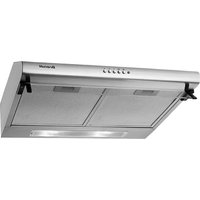
| Product type | Cooker hood |
| Brand | Brandt |
| Model | AD1009X |
| Installation types | External extraction or recirculation (optional charcoal filter) |
| Electrical supply | 220-240 V ~ 50 Hz, single phase |
| Power cable | H05 VVF 3 x 0.75 mm² (neutral, phase, earth) |
| Recommended fuse | 10 or 16 A |
| Number of motor speeds | 3 (low, medium, high) |
| Lighting | 2 halogen lamps |
| Grease filter | Washable metal cassettes (dishwasher safe) |
| Charcoal filter | Optional, replaceable (ref. on rating plate) |
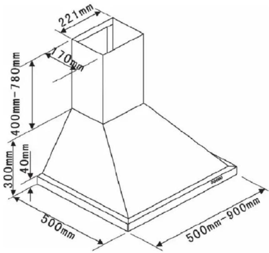
| Duct diameter | Minimum ∅ 125 mm (recommended ∅ 150 mm) |
| Minimum distance above cooking surface | 70 cm (or higher if specified by the hob) |
| Cleaning frequency of grease filters | Every 30 hours of use or once a month |
| Charcoal filter replacement frequency | Every 120 hours of use or at least once a year |
| Exterior surface maintenance | Soapy water, soft cloth (no abrasive products) |
| Lamp replacement | Halogen, accessible after removing the glass cover |
| After-sales service | Fagor, BP 9526, 95069 Cergy Pontoise Cedex, tel. 0892 02 88 07 |
| Repairs | By an approved professional (original parts recommended) |
Frequently Asked Questions - AD1009X BRANDT
User questions about AD1009X BRANDT
0 question about this device. Answer the ones you know or ask your own.
Ask a new question about this device
Download the instructions for your Basket in PDF format for free! Find your manual AD1009X - BRANDT and take your electronic device back in hand. On this page are published all the documents necessary for the use of your device. AD1009X by BRANDT.
USER MANUAL AD1009X BRANDT
FR GUIDE D'UTILISATION
EN GUIDE TO INSTALLATION
natural_image
Black-and-white photo of a person's face with earphones, near a kitchen appliance control panel (no visible text or symbols)Brandt
| FR | 2 |
| EN | 18 |
| DE | 34 |
| IT | 50 |
| DK | 66 |
| NL | 82 |
| SV | 98 |
natural_image
Technical line drawing of a brick chimney with a mounted door and wall fixture (no text or symbols)Fig. 2
natural_image
Line drawing of a conical lamp or fixture with a cylindrical top and base (no text or symbols)Fig. 3
2 / INSTALLATION DE VÔTRE APPAREILFR
• MONTAGE DE LA CHEMINEE
natural_image
Line drawing of a conical lamp with a cylindrical top and base (no text or symbols)Fig. 3

natural_image
Technical line drawing of a chimney mounted on a brick wall, labeled Fig. 6 (no text or symbols on the diagram itself)Fig. 6

natural_image
Line drawing of a chimney with downward arrows indicating airflow or pressure (no text or symbols)Fig. 5
natural_image
Simple line drawing of a refrigerator with a ladder and labeled component C, no text or symbols present2 / INSTALLATION DE VÔTRE APPAREIL FR
- Recyclage
natural_image
Simple line drawing of a cabinet or enclosure with labeled point C and caption 'Fig. 4' (no text or symbols on the diagram itself)Fig. 4
natural_image
Pure technical diagram of a mechanical component with no text, numbers, or symbolsFig. 8
natural_image
Line drawing of a double-bell tower with ventilation ducts (no text or symbols)
natural_image
Architectural line drawing of a chimney and brick wall structure (no text or symbols)Fig. 6
natural_image
Line drawing of a conical hood with downward arrows indicating compression or force, labeled Fig. 5 (no text or symbols on the diagram itself)
Conseil

4 / ENTRETIEN ET NETTOYAGE DE VOTRE APPAREILFR
• NETTOYAGE DE LA SURFACE EXTERIEURE
natural_image
Line drawing of a kitchen range hood with ventilation grilles and a close-up inset showing internal components (no text or symbols)4 / ENTRETIEN ET NETTOYAGE DE VÔTRE APPAREIL FR

Attention
As part of our commitment to constantly improving our products, we reserve the right to make changes to them based on technical advances to their technical and functional features and appearance.

Warning :
Before installing and using your appliance, please carefully read this Guide to Installation and Use, which will allow you to quickly familiarise yourself with its operation.
ENT
1 / NOTICES TO THE USER
- Safety recommendations 20
• Environmental protection 21
• Description of your appliance ____ 22
2 / INSTALLING YOUR APPLIANCE
- Using the evacuation mode 23
- Using the recycling mode ____
- Electrical connections 24
- Assembling the hood 25
- Assembling the ventilation shaft
° Outdoor evacuation 26
° Recycling 27
23
3 / USING YOUR APPLIANCE
• Description of control panel 28
4 / CARING FOR AND CLEANING YOUR APPLIANCE
- Cleaning the fi Iter cartridges 29
- Changing the carbon filter 29
- Cleaning the outer surfaces 30
- Changing the light bulb 30
- Maintaining your appliance 31
5 / TROUBLESHOOTING 32
6 / AFTER-SALES SERVICE 33
1 / NOTICES TO THE USEREN

Attention
Keep this user guide with your appliance. If the appliance is ever sold or transferred to another person, ensure that the new owner receives the user guide. Please become familiar with these recommendations before installing and using your oven. They were written for your safety and the safety of others.
• SAFETY RECOMMENDATIONS
— This oven was designed for use by private persons in their homes.
— This appliance is to be used by adults. Make sure that children do not touch and that they do not treat it as a toy. Make sure that they do not touch the appliance's control panel.
— When you receive the appliance, unpack or have it unpacked immediately. Give it an overall general inspection. Make note of any concerns or reservations on the delivery slip and make sure to keep a copy of this form.
— Your appliance is intended for standard household use. Do not use it for commercial or industrial purposes or for any other purpose than that for which it was designed.
— Do not modify or attempt to modify any of the characteristics of this appliance. This would be dangerous to your safety.
— Repairs must only be carried out by an approved specialist.
— Always unplug the hood before cleaning it or performing other maintenance acts.
— Provide adequate ventilation for the room in the case of simultaneous use of the hood and other appliances powered by an energy source other than electricity. This will prevent the hood from aspirating the combustion gases.
— You should never “fl ambé” dishes under the hood or operate gas rings under the hood without placing cookware on them (the fl ames sucked up into the hood can damage the appliance).
— When frying food under the appliance,
you must carefully monitor the preparation at all times.
Oils and grease brought to very high temperatures can catch fire.
— Respect the recommended frequency of cleanings and fi Iter replacements. The accumulation of grease deposits may cause a fi re.
— The hood should never be used over a combustible fuel burning stove (wood, coal, etc.).
— Never use steam or high-pressure devices to clean your appliance (requirement imposed by electrical safety).
— With a view to constantly improving our products, we reserve the right to modify their technical, functional or aesthetic characteristics, making any changes to their features considered necessary or desirable in view of technical progress.
— In order to easily locate the reference information for your appliance, we recommend that you note these data on the “After-Sales Service Department and Customer Relations” page.
(This page also explains to you where to find this information on your appliance.)
- This appliance is not intended to be used by persons (including children) with reduced physical, sensory or mental abilities, or persons lacking experience or awareness, unless using it with the help of a person responsible for their safety, or under supervision and with prior instruction in its use.

Warning
In the case of a kitchen heated by a device connected to a chimney (a stove, for example) the "recycling" version of the hood should be installed. Do not use the hood without metal fi Iters.
Suitable ventilation should be provided in the room when the hood is used at the same time as appliances operated by gas or another combustible fuel.
1 / NOTICES TO THE USER EN
• ENVIRONMENTAL PROTECTION
— This appliance's packaging material is recyclable. Help recycle it and protect the environment by dropping it off in the municipal receptacles provided for this purpose.
— Your appliance also contains a great amount of recyclable material. It is marked with this label to indicate the used appliances that should not be mixed with other waste. This way,
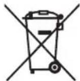
the appliance recycling organised by your manufacturer will be done under the best possible conditions, in compliance with European Directive 2002/96/EC on Waste Electrical and Electronic Equipment. Contact your town hall or your retailer for the used appliance collection points closest to your home.
— We thank you doing your part to protect the environment.

Warning
Installation should only be performed by installers and qualified technicians.

Warning
Remove the protective fi lm from the cartridge fi lter before use.
1 / NOTICES TO THE USEREN
• DESCRIPTION OF YOUR APPLIANCE
2 / INSTALLING YOUR APPLIANCE EN
— The appliance must be unplugged during installation or when any repairs or maintenance work is being performed.
— Ensure that the network voltage corresponds to the voltage noted on the identification plate located inside the hood.
— If the electrical installation at your residence requires any changes in order to hook up your Appliance, call upon a professional electrician.
— If the hood is being used in evacuation mode, do not connect the appliance to a combustion gas exhaust duct (boiler, chimney, etc.) or to a CMV (controlled mechanical ventilation) system.
— Under no circumstances should the exhaust duct empty into the attic.
— Install the hood at a safe distance of at least 70 cm from an electric, gas or combined cooking hob.
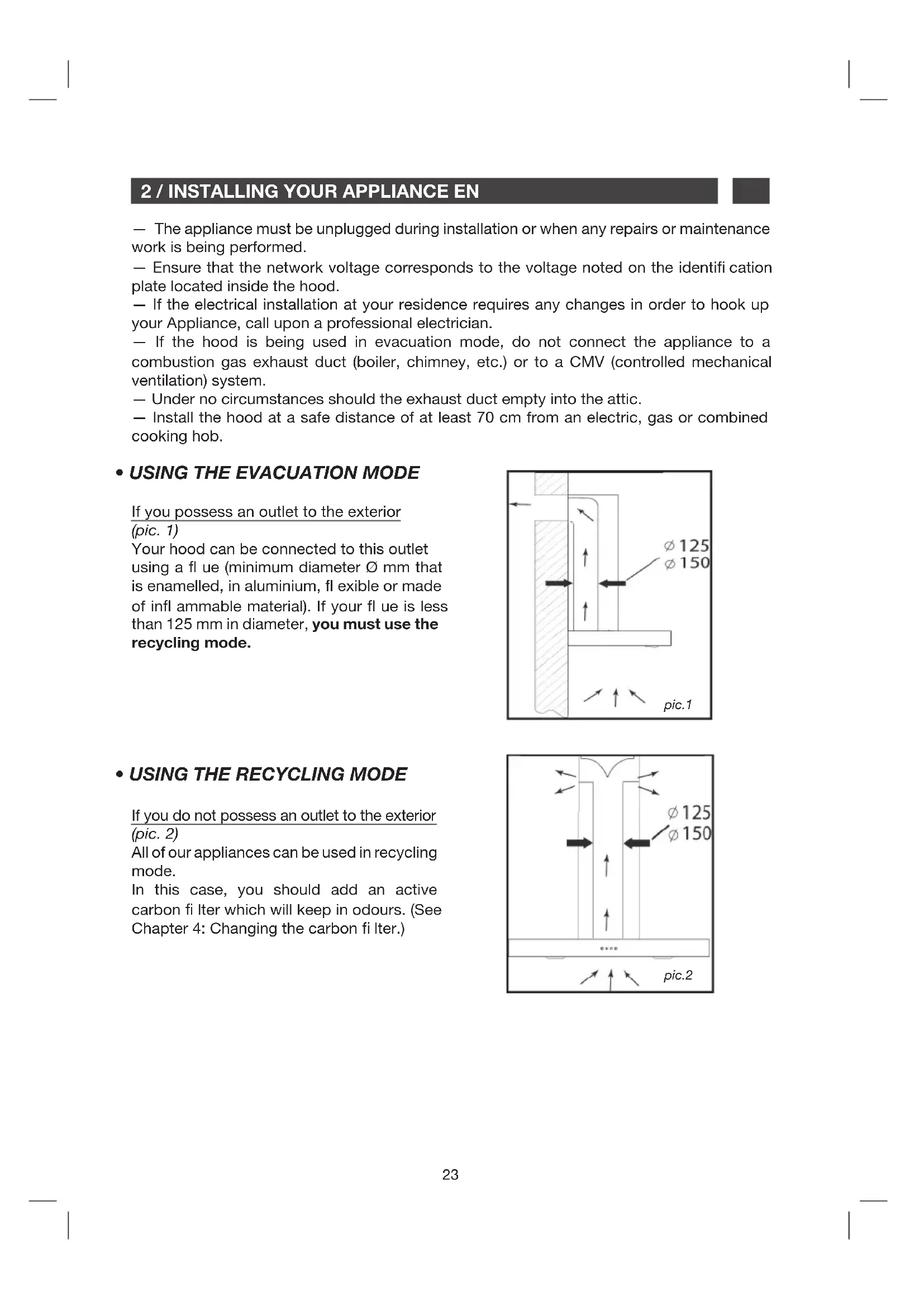
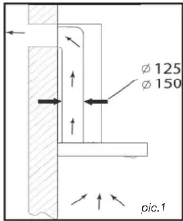
• USING THE EVACUATION MODE
If you possess an outlet to the exterior (pic. 1)
Your hood can be connected to this outlet using a fl ue (minimum diameter ∅ mm that is enamelled, in aluminium, fl exible or made of infl ammable material). If your fl ue is less than 125 mm in diameter, you must use the recycling mode.
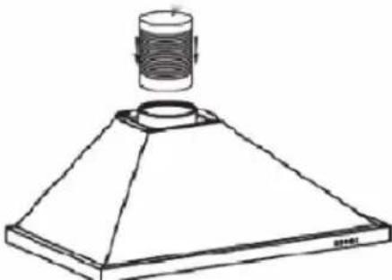
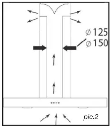
• USING THE RECYCLING MODE
If you do not possess an outlet to the exterior (pic. 2)
All of our appliances can be used in recycling mode.
In this case, you should add an active carbon filter which will keep in odours. (See
Chapter 4: Changing the carbon fi Iter.)
2 / INSTALLING YOUR APPLIANCEEN
• ELECTRICAL CONNECTIONS
During installation and maintenance operations, the appliance must be unplugged from the electrical grid; fuses must be cut off or removed.
The electrical connections are made before the appliance is installed in its housing.
Ensure that:
— the electrical installation has sufficient voltage,
— the electrical wires are in good condition,
— the diameter of the wires complies with the installation requirements.
Warning This applia
This appliance is delivered with a H 05 VVF power cord that has three- 0.75mm^2 conductors (neutral, phase and ground). It must be connected to the main power supply (which should be a 220-240 V single phase current) via a CEI 60083 standardised socket that should remain accessible after installation, in keeping with installation guidelines.
We cannot be held responsible for any accident resulting from an inexistent, defective or incorrect ground lead. The fuse for your installation must be 10 or 16A. If the power cable is damaged, call the after-sales service department in order to avoid danger.
Warning If the ele
If the electrical installation at your residence requires any changes in order to hook up your appliance, call upon a professional electrician.
Warning If the hood
If the hood displays any malfunctions, unplug the appliance or remove the fuse corresponding to the electrical socket where your appliance is plugged in.
2 / INSTALLING YOUR APPLIANCE EN
• ASSEMBLING THE HOOD

Warning
The hood must be installed in compliance with all applicable regulations concerning the ventilation of premises. In France these regulations are described in DTU 61.1 from the CSTB. In particular, the evacuated air should never be conveyed to a duct used to evacuate smoke from appliances that use gas or other combustible fuels. Unused ducts may only be used after approval from a competent specialist.
The minimum distance between the cooking surface and the lowest part of the hood must be 70 cm at least. If the instructions for the hob installed under the hood specify a distance of more than 70 cm, this requirement must be respected.
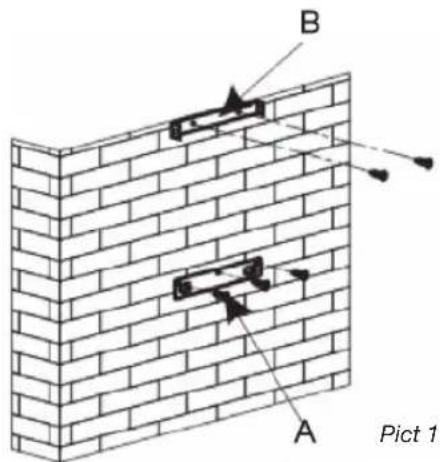
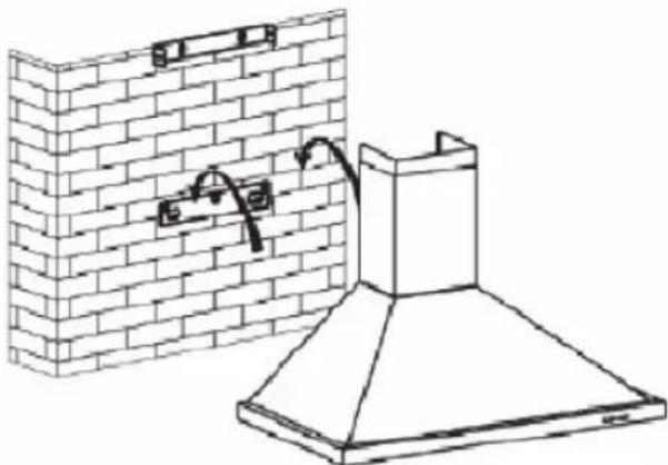
Fixing to the wall :
— Mark a vertical line on the wall centred on the cooktop.
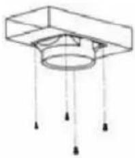
— Mark on the wall the three holes that have to be drilled, using the supplied hood suspension hook and observing the recommended distance. (part A Pic. 1)
— Drill the three 8 mm diameter holes in a suitable position and insert the plugs.
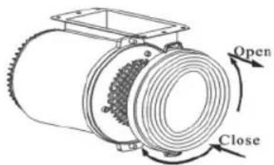
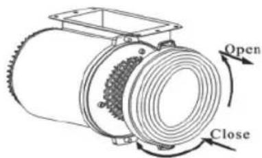
— Before fi xing the hood, mount the non-return valve on the motor outlet -Secure the hood's fi xing support, ensuring that it is perfectly level. (part A Pic. 1)
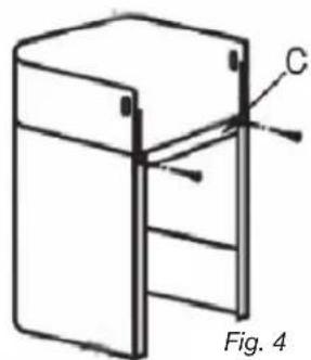
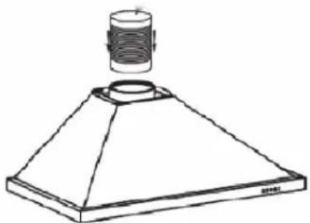
— Fix the extendable evacuation sleeve (not included) to the motor outlet without impeding the movement of the non-return valve.(Pic. 3)
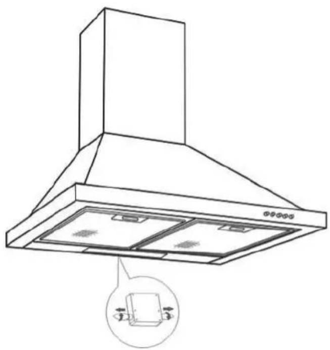
— Fit and secure the body of the hood on this support with the screws provided for this purpose. (Pic. 2)
natural_image
Technical line drawing of a brick chimney with a mounted chimney and wall-mounted fixtures (no text or symbols)Pict 2

natural_image
Line drawing of a conical lampshade with a cylindrical top and base (no text or symbols)Pict 3
2 / INSTALLING YOUR APPLIANCEEN
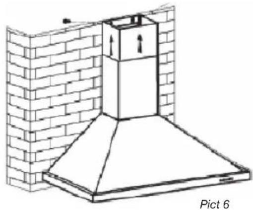
• ASSEMBLING THE VENTILATION SHAFT
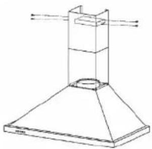
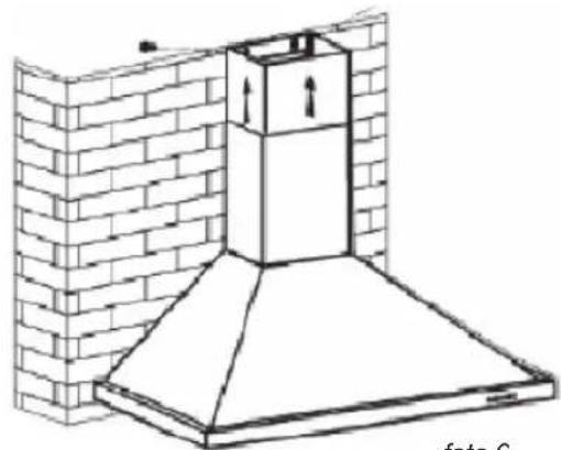
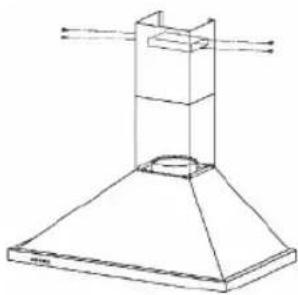
• Outdoor evacuation
— Calculate the fi nal height for fixing the duct support U-bracket (part B Pic. 1)
— Mark the two holes accordingly
— Drill 8 mm diameter holes and secure the duct support bracket, ensuring that it is fixed on the same axis as the hood (part B Pic. 1)
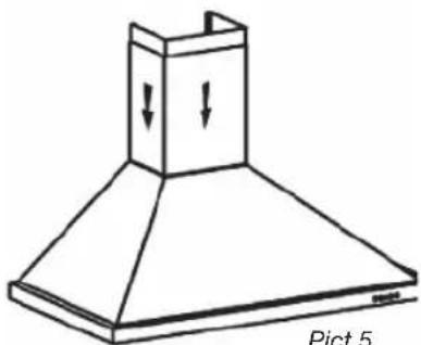
— Fix the fl at bracket behind the lower duct.
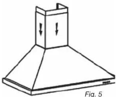
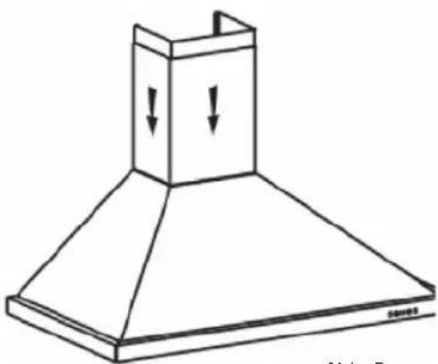
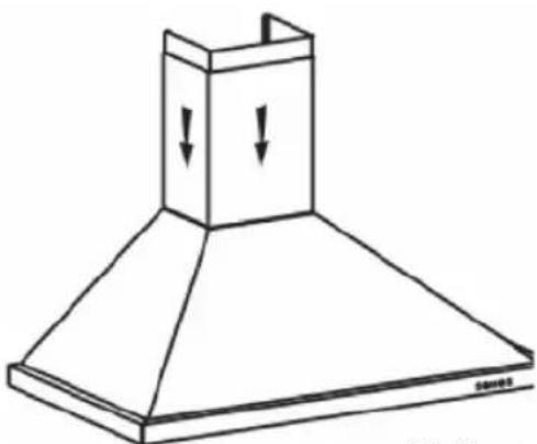
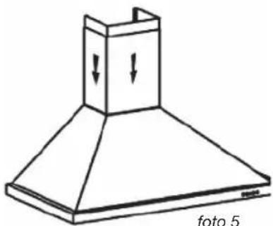
— Fix the two ducts to the hood.(Pic. 5)
— Connect the sleeve to the air outlet to the outside.
— Make the electrical connection to the hood using the mains supply cable.
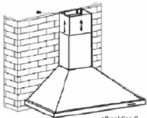
— Lift the upper duct up to the ceiling and fix it to the bracket using the screws.
natural_image
Architectural diagram of a chimney mounted on a brick wall, labeled 'Pict 6' (no text or symbols on the diagram itself)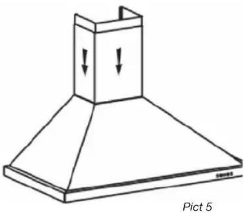
natural_image
Line drawing of a conical exhaust hood with downward arrows indicating airflow or pressure, labeled 'Pict 5' at bottom (no text on the diagram itself)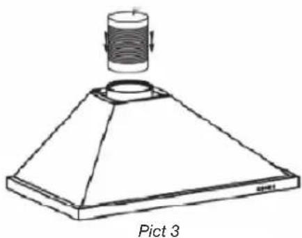
natural_image
Line drawing of a conical lamp or stand with a cylindrical top and base, labeled 'Pict 3' below (no text on diagram itself)
natural_image
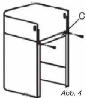
Simple line drawing of a refrigerator with a ladder and labeled point C, no text or symbols present2 / INSTALLING YOUR APPLIANCE EN
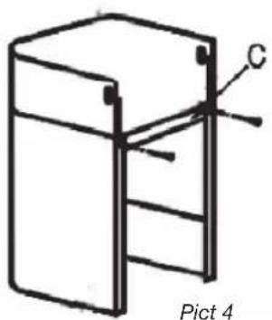
- Recycling
— Calculate the final height for fixing the duct support U-bracket.
— Mark the two holes.
— Drill 8 mm diameter holes and secure the duct support bracket, ensuring that it is fixed in the same axis as the hood.
— Fix the fl at bracket behind the lower duct.
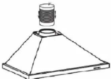
— Fit the sleeve adapter on the deflector (Pic. 8).
— Connect the extendable sleeve to the deflector.
— Fit the two parts of the duct on to the hood (Pic. 5).
— Fit the defl ector (Pic. 8) into the upper duct by the ventilation inlets (Pic. 6)
— Make the electrical connection to the hood using the mains supply cable.
— Lift the upper duct up to the ceiling and fi x it to the bracket using the two screws.
natural_image
Simple line drawing of a cabinet or enclosure with labeled point C and caption 'Pict 4' (no text or symbols on the diagram itself)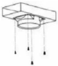
natural_image
Pure technical diagram of a mechanical component with no text, numbers, or symbolsPict 8

natural_image
Line drawing of a double-bell tower with ventilation ducts (no text or symbols)
natural_image
Technical line drawing of a brick chimney with ventilation ducts and chimney (no text or symbols)Pict 6
natural_image
Line drawing of a conical hood with downward arrows indicating compression or force (no text or symbols)
Tip
For optimal use of your appliance, we recommend that you connect the hood to a 150 mm-diameter fl ue (not delivered with the appliance). Minimise the number of angles and bends and the lengths of the fl ue. In the event that the hood will be operated using outdoor evacuation, you should ensure a sufficient inflow of fresh air to avoid a pressure deficiency in the room.

Warning
Do not use tools to remove the safety fi lm of hood.
3 / USING YOUR APPLIANCEEN
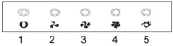
• DESCRIPTION OF CONTROL PANEL
Push button
- Push stop button, and the motor will stop.
- Push the Low button, the buzzer will buzz once, and the motor runs at low speed.
- Push the Mid button, the buzzer will buzz once, and the motor runs at mid speed.
- Push the High button, the buzzer will buzz once, and the motor runs at high speed.
- Push the light button and the two lights will come on. Push it again and the light will turn off.
4 / CARING FOR AND CLEANING YOUR APPLIANCE EN

Warning
Always unplug the hood before cleaning it or performing other maintenance acts. Regular maintenance of your appliance is a guarantee of proper functioning, good performance and durability.

Warning
Failure to respect the guidelines for cleaning the appliance and fi liters may cause fi res. Please carefully adhere to the maintenance recommendations.
- CLEANING THE FILTER CARTRIDGES
They must be cleaned after approximately 30 hours of use or at least once a month. These fi Iters can be cleaned in a vertical position in your dishwasher.
Use a brush, hot water and mild detergent. Rinse and dry them thoroughly before returning them to the hood.
- Dismantling the fi Iter cartridge
— Turn the built-in fi Iter cartridge handle.
— Tilt the filter cartridge downward.
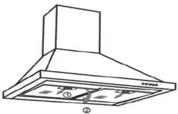
- CHANGING THE CARBON FILTER (optional)
Replace it after approximately 120 hours of use.
— Remove the filter cartridge.
— Turn the carbon filter to remove it.
— Do the operation in the reverse order to put a new filter back.
— Put the fi Iter cartridges back.
4 / CARING FOR AND CLEANING YOUR APPLIANCEEN
• CLEANING THE OUTER SURFACES
To clean the outside of your hood, use soapy water, but never use abrasive creams, corrosive detergents, scrubbing sponges or brushes. Wipe down with a soft, damp cloth.
• CHANGING THE LIGHT BULB

Warning
Before carrying out any work, the power supply to the hood must be turned off, either by unplugging it or by using the circuit breaker switch.
Model with halogen bulb
— Remove the lighting port
— Change the halogen bulb.
— Replace the bulb by repeating these steps in reverse order.
natural_image
Line drawing of a kitchen air conditioner unit with ventilation grilles and a close-up inset showing internal components (no text or symbols)4 / CARING FOR AND CLEANING YOUR APPLIANCE EN

Warning
Before carrying out any work, the power supply to the hood must be turned off, either by unplugging it or by using the circuit breaker switch.
• MAINTAINING YOUR APPLIANCE
| MAINTENANCE WHAT | TO DO | PRODUCTS/ACCESSORIES TO USE |
| Top surface and accessories | Never use metal scouring pads, abrasive products or excessively stiff brushes. | To clean the body and the lighting port, you should use only commercial household cleaning products diluted in water and then rinse using clean water, drying with a soft cloth. |
| Filter cartridge | This fi Iter traps fatty vapours and dust. This component plays an important role in ensuring the effectiveness of your hood.In the event of tough stains, use a non-abrasive cream, then rinse with clean water. | Use a commercial household cleaning product then rinse abundantly and dry. These fi Iters can be cleaned in a vertical position in your dishwasher.(Do not allow them to touch dirty dishes or silverware.) |
| Activated carbon fi Iter | This fi Iter traps odours and must be changed at least once a year depending on your level of use.You should order these fi Iters from your dealer (quoting the reference shown on the identifi cation plate located inside the hood) and note the date the fi Iter was changed. |
To preserve your appliance, we recommend that you use Clearit cleaning products.

Professional expertise serving individuals
Clearit offers you professional products and solutions designed for the daily care of your household appliances and kitchens.
They are on sale at your regular retailer, along with a complete line of accessories and consumable products.
5 / TROUBLESHOOTINGEN
| SYMPTOMS | SOLUTIONS |
| The hood is not working... | Ensure that:• The power is not cut off.• A speed has been selected. |
| The hood is not operating effectively... | Ensure that:• The selected motor speed is suffi cient for the quantity of smoke and vapours to be cleared.• The kitchen is suffi ciently ventilated to allow for fresh air intake.• The carbon fi lter is not worn (hood operating in recycling mode). |
| The hood stopped working. | Ensure that:• The power is not cut off.• The single-pole cut-off device was not activated. |
6 / AFTER-SALES SERVICE EN
Any maintenance on your equipment should be undertaken by :
— either your dealer,
— or another qualified mechanic who is an authorized agent for the brand appliances.
When making an appointment, state the full reference of your equipment (model, type and serial number). This information appears on the manufacturer's nameplate attached to your equipment.
DE 34
natural_image
Technical line drawing of a brick chimney with a mounted chimney and wall-mounted fixtures (no text or symbols)Abb. 2
natural_image
Line drawing of a conical lamp or fixture with a cylindrical top and base (no text or symbols)Abb. 3
2 / ANSCHLIESSEN DES GERÄTSDE
• MONTAGE DER ROHRABDECKUNG
natural_image
Line drawing of a conical lamp or fixture with a cylindrical top and base (no text or symbols)Abb. 3

natural_image
Architectural diagram of a chimney mounted on a brick wall, showing structural details without any text or symbols.Abb. 6
natural_image
Line drawing of a conical exhaust hood with downward arrows indicating airflow or ventilation (no text or symbols)Abb. 5
natural_image
Simple line drawing of a refrigerator with labeled component C, no text or symbols present2 / ANSCHLIESSEN DES GERÄTS DE
• Umluft
natural_image
Simple line drawing of a 3D rectangular frame with a vertical support and labeled point C, no text or symbols present.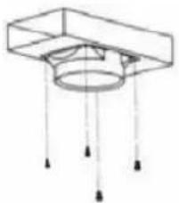
natural_image
Pure technical diagram of a mechanical component with no text, numbers, or symbolsAbb. 8

natural_image
Line drawing of a double-bone kitchen chimney with ventilation ducts (no text or symbols)
natural_image
Line drawing of a brick chimney with ventilation ducts and airflow direction arrows (no text or symbols)Abb. 6

natural_image
Line drawing of a conical hood with downward arrows indicating compression or force (no text or symbols)
Hinweis

natural_image
Line drawing of a kitchen range hood with ventilation slots and a magnified inset showing internal components (no text or symbols)natural_image
Diagram showing a brick chimney with a wall and a side-mounted fan, labeled 'foto 2' (no text or symbols on the diagram itself)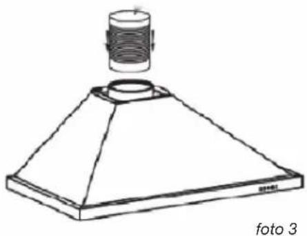
natural_image
Line drawing of a conical lamp or fixture with a cylindrical top and base, labeled 'foto 3' at the bottom (no other text or symbols)2 / INSTALLAZIONE DEL DISPOSITIVOIT
• MONTAGGIO DELLA CANNA FUMARIA
natural_image
Line drawing of a conical lamp or fixture with a cylindrical top and base (no text or symbols)foto 3
natural_image
Architectural diagram of a chimney mounted on a brick wall, showing structural details without any text or symbols.foto 6
natural_image
Line drawing of a chimney with downward arrows indicating airflow or pressure (no text or symbols)foto 5

natural_image
Simple line drawing of a refrigerator with a label 'C' and 'foto 4' at the bottom (no text or symbols on the diagram itself)2 / INSTALLAZIONE DEL DISPOSITIVO IT
- Riciclaggio
natural_image
Simple line drawing of a cabinet or enclosure with labeled point C and caption 'foto 4' (no text or symbols on the diagram itself)
natural_image
Pure technical diagram of a mechanical component with no text, numbers, or symbolsfoto 8

natural_image
Line drawing of a double-bell tower with ventilation ducts (no text or symbols)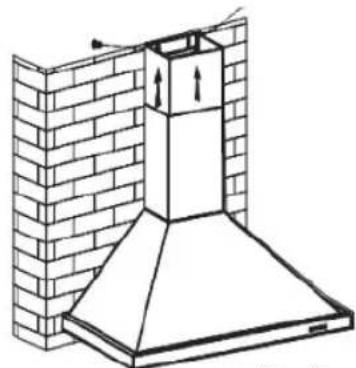
natural_image
Architectural line drawing of a chimney and brick wall structure (no text or symbols)foto 6
natural_image
Line drawing of a kitchen chimney with downward arrows indicating airflow or movement (no text or symbols)
Nota

4 / MANUTENZIONE E PULIZIA DEL DISPOSITIVOIT
• PULIZIA DELLA SUPERFICIE ESTERNA
natural_image
Line drawing of a kitchen air conditioner unit with ventilation grilles and a close-up inset showing internal components (no text or symbols)4 / MANUTENZIONE E PULIZIA DEL DISPOSITIVO IT

Attenzione
2 / INSTALLATION AF APPARATET
• BRUG MED RECIRKULERINGSVERSIONEN
natural_image
Technical line drawing of a brick chimney with a chimney cover and wall-mounted fixtures (no text or symbols)Illu. 2

natural_image
Line drawing of a conical lamp or fixture with a cylindrical top and base (no text or symbols)Illu. 3
2 / INSTALLATION AF APPARATET DK
• SAMLING AF VENTILATIONSSKAKTEN
natural_image
Line drawing of a conical lamp or fixture with a cylindrical top and base (no text or symbols)Illu. 3

natural_image
Technical line drawing of a chimney mounted on a brick wall, showing structural details without any text or symbols.Illu. 6

natural_image
Line drawing of a chimney with downward arrows indicating airflow or pressure (no text or symbols)Illu. 5
natural_image
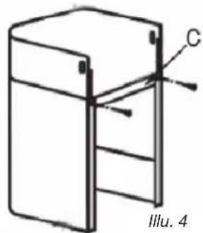
Simple line drawing of a refrigerator with labeled component C and label 'Illu. 4' (no text or symbols on the diagram itself)2 / INSTALLATION AF APPARATET DK
- Recirkulering
natural_image
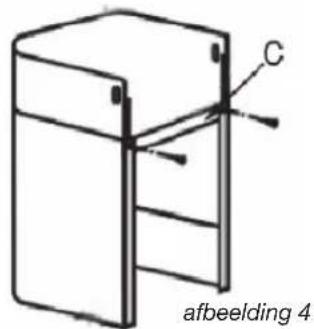
Simple line drawing of a cabinet or enclosure with labeled point C and reference number IIIu. 4 (no text or symbols on the diagram itself)
natural_image
Pure technical diagram of a mechanical component with no text, numbers, or symbolsIllu. 8

natural_image
Line drawing of a double-bell tower with ventilation ducts (no text or symbols)
natural_image
Technical line drawing of a brick chimney with ventilation ducts and chimney (no text or symbols)Illu. 6

natural_image
Line drawing of a double-hopper kitchen chimney with downward arrows indicating airflow or ventilation (no text or symbols)
Råd
4 / PLEJE OG RENG∅RING AF APPARATET DK

Advarsel
4 / PLEJE OG RENG∅RING AF APPARATETDK
- RENG∅RING AF DE YDRE OVERFLADER
natural_image
Line drawing of a kitchen air conditioner unit with ventilation grilles and a close-up inset showing internal components (no text or symbols)4 / PLEJE OG RENG∅RING AF APPARATET DK

Advarsel
2 / INSTALLATIE VAN HET APPARAATNL
natural_image
Technical line drawing of a brick chimney with attached piping and a side-mounted chimney (no text or symbols)afbeelding 2
natural_image
Line drawing of a conical lamp or fixture with a cylindrical top and base (no text or symbols)afbeelding 3
2 / INSTALLATIE VAN HET APPARAATNL
• MONTAGE VAN HET AFVOERKANAAL
natural_image
Line drawing of a conical lamp or fixture with a cylindrical top and base (no text or symbols)afbeelding 3
natural_image
Technical line drawing of a brick chimney mounted on a wall, showing structural details (no text or symbols)afbeelding 6

natural_image
Line drawing of a chimney with downward arrows indicating airflow or pressure (no text or symbols)afbeelding 5
natural_image
Pure technical diagram of a mechanical component with no text, numbers, or symbolsafbeelding 8
natural_image
Line drawing of a double-bell tower with ventilation ducts (no text or symbols)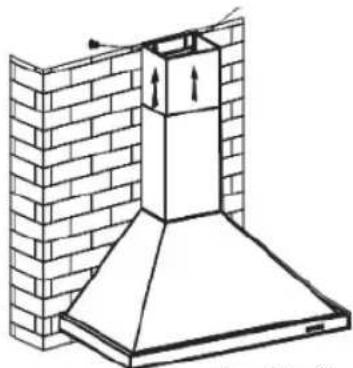
natural_image
Technical line drawing of a brick chimney with ventilation duct (no text or symbols)afbeelding 6

natural_image
Line drawing of a conical hood with downward arrows indicating compression or damage (no text or symbols)afbeelding 5

Advies
4 / ONDERHOUD EN REINIGING VAN HET APPARAATNL
• REINIGING VAN DE BUITENZIJDE
natural_image
Line drawing of a kitchen range hood with ventilation grilles and a close-up inset showing internal components (no text or symbols)4 / ONDERHOUD EN REINIGING VAN HET APPARAAT NL

Attentie
natural_image
Technical line drawing of a brick chimney with attached piping and a chimney cover (no text or symbols)fig. 2

natural_image
Line drawing of a conical lamp or fixture with a cylindrical top and base (no text or symbols)fig. 3
2 / INSTALLATION AV APPARATENSV
• MONTERING AV SKORSTENEN
- Utvändigt utlopp
natural_image
Technical line drawing of a chimney mounted on a brick wall, labeled 'fi g. 6' (no text or symbols on the diagram itself)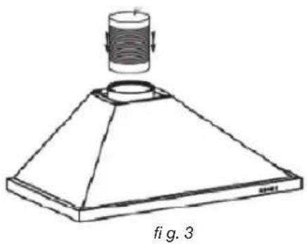
natural_image
Line drawing of a conical lamp or fixture with a cylindrical top and base, labeled 'fig. 3' (no text or symbols on the diagram itself)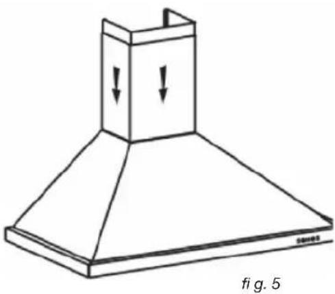
natural_image
Line drawing of a conical exhaust hood with downward arrows indicating airflow or pressure, labeled 'fig. 5' at bottom (no text or symbols on the diagram itself)
natural_image
Simple line drawing of a refrigerator with a label 'C' and figure number 'fig. 4' (no text or symbols on the diagram itself)2 / INSTALLATION AV APPARATEN SV
- Återcirkulation
natural_image
Pure technical diagram of a mechanical component with no text, numbers, or symbolsfig. 8

natural_image
Line drawing of a double-bell tower with ventilation ducts (no text or symbols)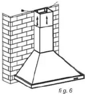
natural_image
Architectural diagram of a chimney structure with brick wall and chimney, labeled 'fig. 6' (no text or symbols on the diagram itself)
natural_image
Simple line drawing of a cabinet or enclosure with labeled component C, no text or symbols present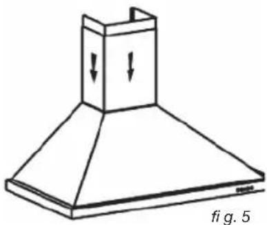
natural_image
Line drawing of a conical exhaust hood with downward arrows indicating airflow or pressure, labeled 'fig. 5' at bottom (no text or symbols on the diagram itself)• UTBYTE AV KOLFILTRET (alternativt)
4 / UNDERHÅLL OCH RENGÖRING AV APPARATENSV
• RENGÖRING AV UTVÄNDIGA YTOR
natural_image
Line drawing of a kitchen range hood with ventilation slots and a magnified inset showing internal components (no text or symbols)4 / UNDERHÅLL OCH RENGÖRING AV APPARATEN SV

OBS

- / INSTALLATION DE VÔTRE APPAREILFR
- • MONTAGE DE LA CHEMINEE
- / INSTALLATION DE VÔTRE APPAREIL FR
- - Recyclage
- Conseil
- / ENTRETIEN ET NETTOYAGE DE VOTRE APPAREILFR
- • NETTOYAGE DE LA SURFACE EXTERIEURE
- / ENTRETIEN ET NETTOYAGE DE VÔTRE APPAREIL FR
- Attention
- Warning :
- ENT
- / NOTICES TO THE USER
- / INSTALLING YOUR APPLIANCE
- / USING YOUR APPLIANCE
- / CARING FOR AND CLEANING YOUR APPLIANCE
- / NOTICES TO THE USEREN
- • SAFETY RECOMMENDATIONS
- Warning
- / NOTICES TO THE USER EN
- • ENVIRONMENTAL PROTECTION
- / INSTALLING YOUR APPLIANCE EN
- • USING THE EVACUATION MODE
- • USING THE RECYCLING MODE
- / INSTALLING YOUR APPLIANCEEN
- • ELECTRICAL CONNECTIONS
- Warning This applia
- Warning If the ele
- Warning If the hood
- • ASSEMBLING THE HOOD
- Fixing to the wall :
- • ASSEMBLING THE VENTILATION SHAFT
- • Outdoor evacuation
- - Recycling
- Tip
- / USING YOUR APPLIANCEEN
- • DESCRIPTION OF CONTROL PANEL
- Push button
- / CARING FOR AND CLEANING YOUR APPLIANCE EN
- - CLEANING THE FILTER CARTRIDGES
- - Dismantling the fi Iter cartridge
- - CHANGING THE CARBON FILTER (optional)
- / CARING FOR AND CLEANING YOUR APPLIANCEEN
- • CLEANING THE OUTER SURFACES
- • CHANGING THE LIGHT BULB
- Model with halogen bulb
- Professional expertise serving individuals
- / AFTER-SALES SERVICE EN
- / ANSCHLIESSEN DES GERÄTSDE
- • MONTAGE DER ROHRABDECKUNG
- / ANSCHLIESSEN DES GERÄTS DE
- • Umluft
- Hinweis
- / INSTALLAZIONE DEL DISPOSITIVOIT
- • MONTAGGIO DELLA CANNA FUMARIA
- / INSTALLAZIONE DEL DISPOSITIVO IT
- - Riciclaggio
- Nota
- / MANUTENZIONE E PULIZIA DEL DISPOSITIVOIT
- • PULIZIA DELLA SUPERFICIE ESTERNA
- / MANUTENZIONE E PULIZIA DEL DISPOSITIVO IT
- Attenzione
- / INSTALLATION AF APPARATET
- • BRUG MED RECIRKULERINGSVERSIONEN
- / INSTALLATION AF APPARATET DK
- • SAMLING AF VENTILATIONSSKAKTEN
- - Recirkulering
- Råd
- / PLEJE OG RENG∅RING AF APPARATET DK
- Advarsel
- / PLEJE OG RENG∅RING AF APPARATETDK
- - RENG∅RING AF DE YDRE OVERFLADER
- / INSTALLATIE VAN HET APPARAATNL
- • MONTAGE VAN HET AFVOERKANAAL
- Advies
- / ONDERHOUD EN REINIGING VAN HET APPARAATNL
- • REINIGING VAN DE BUITENZIJDE
- / ONDERHOUD EN REINIGING VAN HET APPARAAT NL
- Attentie
- / INSTALLATION AV APPARATENSV
- • MONTERING AV SKORSTENEN
- - Utvändigt utlopp
- / INSTALLATION AV APPARATEN SV
- - Återcirkulation
- • UTBYTE AV KOLFILTRET (alternativt)
- / UNDERHÅLL OCH RENGÖRING AV APPARATENSV
- • RENGÖRING AV UTVÄNDIGA YTOR
- / UNDERHÅLL OCH RENGÖRING AV APPARATEN SV
- OBS
Brand : BRANDT
Model : AD1009X
Category : Basket