
BHC4611B - Basket BRANDT - Free user manual and instructions
Find the device manual for free BHC4611B BRANDT in PDF.

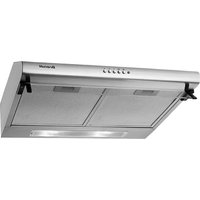
| Product type | Extractor hood |
| Brand | Brandt |
| Model | BHC4611B |
| Power supply | 230 V / 50 Hz |
| Lighting power | 2 x 2 W (LED) |
| Number of speeds | 3 (Low, Medium, High) |
| Maximum airflow rate | 164.5 m³/h |
| Airflow rate at minimum speed | 68 m³/h |
| Maximum noise level | 58.5 dB(A) |
| Grease filter type | Aluminium (washable) |
| Activated carbon filter | Optional, replacement every 3 to 6 months |
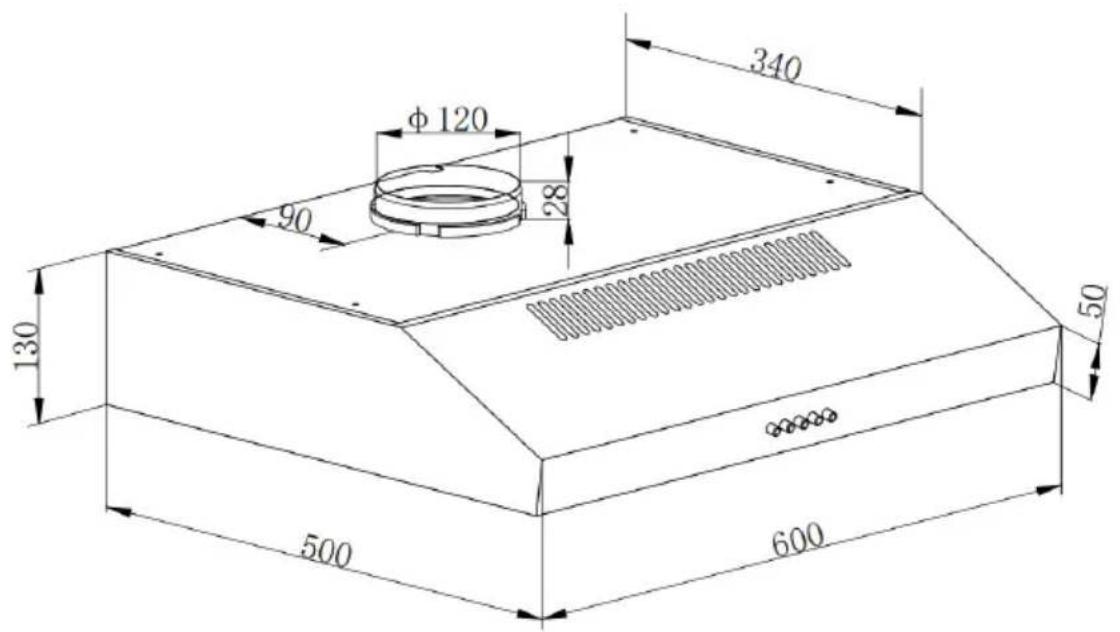
| Evacuation mode | Recirculation or external evacuation (diameter 120 mm) |
| Minimum safety distance (gas cooking) | 70 cm |
| Recommended distance above cooking surface | 65 to 75 cm |
| Installation type | Wall-mounted or under cabinet |
| Annual energy consumption | 58.5 kWh/year |
| Energy efficiency index | 83.8 |
| Surface material | Stainless steel |
| Filter cleaning | Soak 3 min in soapy water, soft brush |
| Bulb replacement | By an approved professional (LED not replaceable by the user) |
| After-sales service | 0 892 02 88 01 (€0.50/min + call charges) or 09 69 39 25 25 (free service + call charges) |
Frequently Asked Questions - BHC4611B BRANDT
User questions about BHC4611B BRANDT
0 question about this device. Answer the ones you know or ask your own.
Ask a new question about this device
Download the instructions for your Basket in PDF format for free! Find your manual BHC4611B - BRANDT and take your electronic device back in hand. On this page are published all the documents necessary for the use of your device. BHC4611B by BRANDT.
USER MANUAL BHC4611B BRANDT
natural_image
Black-and-white photo of a bowl with leaf garnish, no visible text or symbolsGUIDE D'INSTALLATION FR GUIDE TO INSTALLATION EN
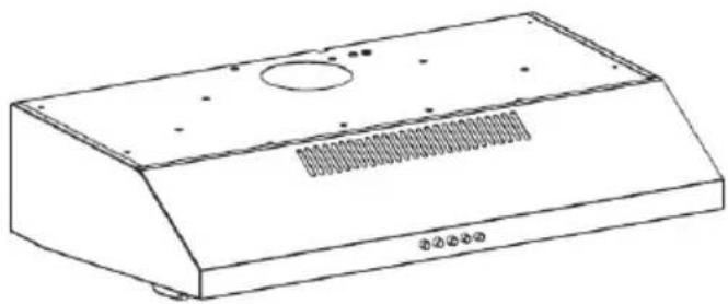
Hotte de cuisine standard
Standard Cooker Hood
BHC4611B BHC4611X BHC4611W
natural_image
Line drawing of a standard kitchen air conditioner unit (no text or symbols)Brandt
Chère Cliente, Cher Client,
natural_image
Diagram of airflow around a mechanical component with directional arrows indicating movement (no text or symbols)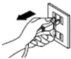
natural_image
Hand holding a wall socket with an arrow indicating left motion (no text or symbols)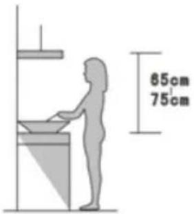
Image 1
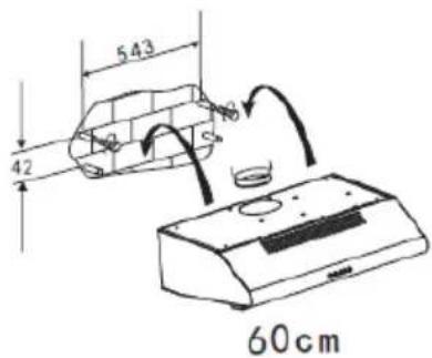
Image 2
FR 2 / INSTALLATION
natural_image
Diagram of a mounted device with a cylindrical component above it, placed on a brick wall (no text or symbols)Image 3
natural_image
Technical line drawing of a rectangular electronic component with circular cutouts and mounting holes (no text or symbols)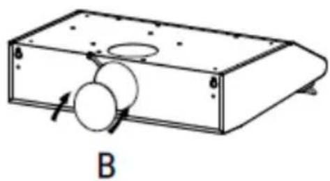
natural_image
Technical line drawing of a rectangular device with circular components and an arrow indicating direction (no text or symbols)Image 4
natural_image
Abstract geometric sculpture with a figure holding a string and a circular element, no text or symbols present.- REMPLACEMENT ET NETTOYAGE DES FILTRES À GRAISSE

NOTE:
natural_image
Cartoon illustration of a yellow exclamation mark with a smiling face and an exclamation mark below (no text or symbols)Important :
natural_image
Technical line drawing of an air conditioner unit with two fans and a handle (no text or symbols)Image 1
flowchart
graph LR
    A["LED"] <--> B["LED"]
natural_image
Technical line drawing of an air conditioner unit with internal components and wiring (no text or symbols)Image 2
• PROTECTION DE L'ENVIRONNEMENT
natural_image
Symbol of a trash bin crossed with no text or numbers, representing waste sorting or disposal (no text present)● INTERVENTIONS FRANCE
Thank you for buying a BRANDT product and for your confidence in our company.
This product has been designed and manufactured for you considering your lifestyle and your requirements, so that it meets your expectations in the best way possible. We have invested it with our expertise, spirit of innovation and all the enthusiasm which has driven us for more than 60 years.
So that we are always able to satisfy your requirements as well as possible, our customer service is available, ready to listen and answer all your questions or suggestions.
You can also visit our website www.brandt.com where you will find our latest innovations as well as additional useful information.
BRANDT is happy to support you daily and hopes you will enjoy your purchase to the full..

Important: Before starting your machine, please read this guide for installation and use carefully in order to familiarise yourself with how it operates quickly.
As part of our commitment to constantly improving our products, we reserve the right to make changes to them based on technical advances to their technical and functional features and appearance.

Warning :
Before installing and using your appliance, please carefully read this Guide to Installation and Use, which will allow you to quickly familiarise yourself with its o1.09peration.
CONTENTS
EN
1 / SAFETY INSTRUCTIONS ......26
2 / INSTALLATION....33
3 / START USING YOUR COOKER HOOD....36
4 / TROUBLESHOOTING ....37
5 / MAINTENANCE AND CLEANING....38
6 / ENVIRONMENT PROTECTION ....42
7 / AFTER-SALES SERVICE 43
8 / ECODESIGN INFORMATION / TECHNICAL PRODUCT CHE ....44

Attention
keep this user guide with your appliance. If the appliance is ever sold or transferred to another person, ensure that the new owner receives the user guide. please become familiar with these recommendations before installing and using your appliance. They were written for your safety and the safety of others.
Safety and important precautions

These instructions are also available on the Brandt website.
Please take heed of this advice when installing and using your appliance. These instructions are intended to protect your safety and the safety of others. Keep this manual with your appliance. If you sell or give the appliance to anyone else, make sure that you also give them this manual.
- In order to constantly improve our products, we reserve the right to make changes to their technical, functional or aesthetic characteristics in line with technological progress.
● Make a note of the references of your appliance on the "Consumer Service" page so that you can readily find them in future
- This appliance is designed for use by consumers in the home. Do not use it for commercial or industrial purposes or for any other purpose for which it is not intended.
- Unpack the appliance as soon as you receive it. Check its general appearance. Make a note of any reservations on the delivery slip and keep a copy.
- This appliance can be used by children aged under 8 and by persons with diminished physical, sensory or mental capacities, or persons without any experience or knowledge, provided that they are properly attended to or are given the instructions on how to use the appliance in complete safety and that any potential risks are anticipated. Children must not play with this appliance. The appliance must not be cleaned and maintained by unattended children.
● CAUTION: The accessible parts of this
appliance may become hot when used with cooking equipment.
Electrical risks :
- All the power supply circuits must be disconnected before touching the connection terminals. If the power cord is damaged, it must be replaced by the manufacturer, its after-sales service or a similarly qualified person in order to avoid any danger.
- The appliance can be disconnected by using an accessible power outlet or by incorporating a switch in the fixed lines, in accordance with the installation rules.
- Do not change or attempt to change the characteristics of this appliance. Doing so can be dangerous.
- The appliance must only be repaired by an approved specialist.
● Always disconnect the hood before cleaning or maintaining it. - Never use steam or high-pressure tools to
clean your appliance (for the purposes of electrical safety).
- The appliance can be disconnected by using an accessible power outlet or by incorporating a switch in the fixed lines, in accordance with the installation rules.
- Do not change or attempt to change the characteristics of this appliance. Doing so can be dangerous.
- The appliance must only be repaired by an approved specialist.
● Always disconnect the the hood before cleaning or maintaining it. - Never use steam or high-pressure tools to clean your appliance (for the purposes of electrical safety).
Risk of asphyxiation :
- The regulations applying to the evacuation of air must be obeyed. The air must not be sent into a duct used to evacuate fumes from appliances that use gas or other fuels (this
does not apply to appliances that only emit air into the room).
- The room must be suitably ventilated when the range hood is used at the same time as appliances that use gas or other fuels (this does not apply to appliances that only emit air into the room).
Risk of fire :
- It is forbidden toflambé food or to turn on gas rings that are not covered by a cooking recipient beneath the hood, as the flames may sucked in and damage the appliance.
- Keep a constant eye on fryers used beneath the hood. When heated to very high temperatures, oil and fat can catch fire.
- Clean the appliance and replace the filters at the recommended frequency. Accumulated deposits of grease can cause a fire.
- It is forbidden to use the hood above a fuel fire (wood, coal, etc.).
- If the hood is installed above a gas-fired
appliance, leave at least 70 cm between the top of the range and the underside of the hood. If the instructions of the range installed under the hood specify a distance greater than 70 cm, then this distance must be respected.

WARNING
In the case of a kitchen heated by a device connected to a chimney (a stove, for example) the “recycling” version of the hood should be installed. Do not use the hood without metal filters.
Suitable ventilation should be provided in the romm when the hood is used at the same time as appliances operated by gas or another combustible fue.
EN 1 / Safety instructions
• DESCRIPTION OF YOUR APPLIANCEL
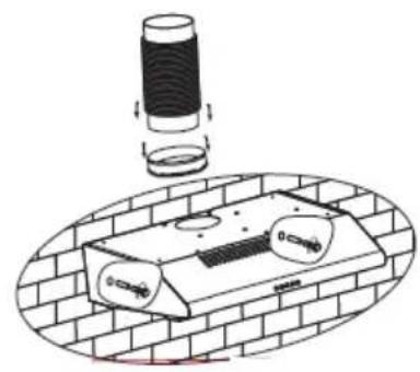
● MOUNTING OF THE V-FLAP
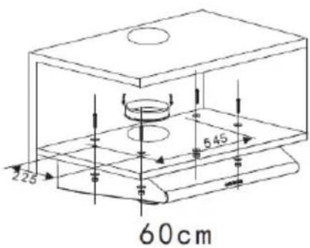
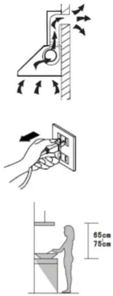
If you have an outlet to the outside, your cooker hood can be connected as below picture by means of an extraction duct (enamel, aluminum, flexible pipe or non-flammable material with an interior diameter of 120mm)
Before installation, turn the unit off and unplug it from the outlet.
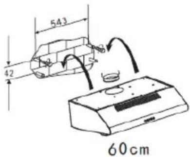
The cooker hoods should be placed at a distance of 65-75cm from the cooking surface for best effect. See Pic 1.
● Method A: (Wall mounting)
- To install onto the wall, drill 4 holes of ∅ 8mm on a suitable place according with the centre distance of hole in the back of the cooker hood. See Pic 2
- Insert the nut into the holes.
- Insert the screws into the nuts and tight.
- Put up the cooker hood onto the fixed screws.
- Then use the attached accessories enclosed to turn the screws into the two holes of inside the hood, and then fix the screws to tighten the hood onto the wall.
- Put the outlet onto the cooker hood.

Warning
Installation should only be performed by installers and qualified technicians.

Warning
Remove the protective film from the cartridge filter before use.
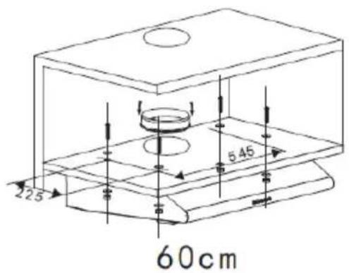
● Method B (Cabinet mounting)
- Drill 4 holes of ∅ 6mm at the bottom of the hanging cupboard.
- Put the outlet to the cooker hood, then install the cooker hood on the bottom of the
Pic 1
Pic 2
2 / INSTALLATION
EN
cupboard, tighten the cooker hood with
EN 2 / INSTALLATION
enclosed 4 screws.
- Install the adjusted board on the bottom of the hood in order to keep out the gap between hood back and cupboard.
- Lay the expansion pipe (not included) on the valve. Lift up the expansion pipe till it out of the wall through the hole on the wall.
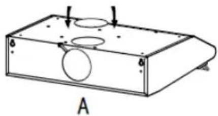
Notice: There are 2 methods for ventilation, including 'horizontal ventilation' and 'vertical ventilation'. Please pay attention to the ventilation method when installation.
Horizontal ventilation: See Pic 4A, please use the cover to seal the outlet on the top, then the air can be vented from back.
Vertical ventilation: See Pic 4B, please use the cover to seal the outlet on the back, then the air can be vented from top.
natural_image
Diagram of a pipe installation with a cylindrical component and a brick-lined base (no text or symbols)Pic 3

natural_image
Technical line drawing of a rectangular electronic component with circular holes and mounting holes, labeled A (no text or symbols on the diagram itself)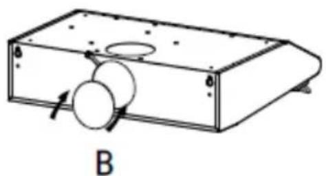
natural_image
Technical line drawing of a rectangular device with two circular components and an arrow indicating direction (no text or symbols)Pic 4
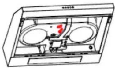
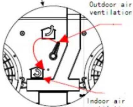
• Air ventilation setting
Outdoor air ventilation: Turn the adjuster to outdoor position(pic.5A), install the outlet, turn on the cooker hood, then the air will be vented from the outside outlet.
Indoor air ventilation: Turn the adjuster to indoor position (pic.5B), install the outlet cover, turn on the cooker hood, then the air can be vented from the inside outlet.

Warning
For safety reason, please use only the same size of fixing or mounting screws which are recommended in this instruction manual.

Warning
Failure to install the screws or fixing device in accordance with these instructions may result in electrical hazards.
natural_image
Technical line drawing of a mechanical device with two circular components and a red indicator symbol (no text or labels)A
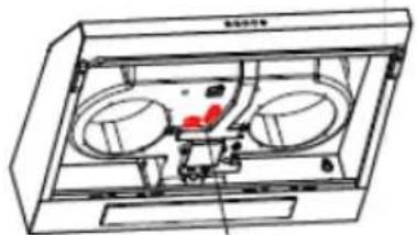
natural_image
Technical line drawing of a mechanical device with two circular components and a red indicator light (no text or symbols)B
Pic 5
EN 3 / Using your appliance
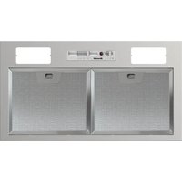
● Description of the control panel
- Push the stop button, and the motor will stop.
- Push the low button, and the motor will run at low speed.
- Push the middle button, and the motor will run at mid speed.
- Push the high button, and the motor will run at high speed.
- Push the light button and the two lights will illuminate. Push it again and the light will turn off.

Stop

Low

Mid

High

Lamp
| Fault | Possible Cause | Solution |
| Light on, but motor does not work | Fan switch turned off | Select a fan switch position. |
| Fan switch failed | Contact service center. | |
| Motor failed | Contact service center. | |
| Light does not work, motor does not work | House fuses blown | Reset/Replace fuses. |
| Mains power cable is loose or disconnected | Refit mains power cable to power outlet.Switch power outlet on. | |
| Oil leakage | One way valve and the outlet are not tightly sealed | Take down the one way valve and seal with sealant. |
| Leakage from the connection of chimney and cover | Take chimney down and seal. | |
| Lights not working | Broken or faulty bulbs | Replace blubs as per this instruction. |
| Insufficient suction | The distance between the cooker hood and the gas top is too far | Refit the cooker hood to the correct distance. |
| The Cooker hood inclines | The fixing screw is not tight enough | Tighten the hanging screw and make it horizontal. |

Note :
Any electrical repairs to this appliance must conform to your local, state and federal laws. Please contact the service centre if in any doubt before undertaking any of the above. Always disconnect the unit from the power source when opening the unit.
EN 5 / MAINTENANCE AND CLEANING
- Caution :
Before maintenance or cleaning is carried out, the cooker hood should be disconnected from the mains power supply. Ensure that the cooker hood is switched off at the wall socket and the plug removed.
External surfaces are susceptible to scratches and abrasions, so please follow the cleaning instructions to ensure the best possible result is achieved without damage.
GENERAL
Cleaning and maintenance should be carried out with the appliance cold especially when cleaning. Avoid leaving alkaline or acid substances (lemon juice, vinegar etc.) on the surfaces.
• STAINLESS STEEL
The stainless steel must be cleaned regularly (e.g. weekly) to ensure a long life expectancy. Dry with a clean soft cloth. A specialized stainless steel cleaning fluid may be used.

Note :
Ensure that wiping is done along with the grain of the stainless steel to prevent any unsightly crisscross scratching patterns from appearing.
• CONTROL PANEL SURFACE
The inlay control panel can be cleaned using warm soapy water. Ensure the cloth is clean and well wrung before cleaning. Use a dry soft cloth to remove any excess moisture left after cleaning.

Important:
Using neutral detergents and avoid using harsh cleaning chemicals, strong household detergents or products containing abrasives, as this will affect the appearance of the appliance and potentially remove any printing of artwork on the control panel and will void manufactures warrantee.
natural_image
Abstract geometric illustration with a figure holding a guitar and a circular object, no text or symbols present.- CHANGING AND CLEANING THE GREASE FILTERS
The filters can be cleaned by hand. Soak them for about 3 minute in water with a grease-loosening detergent and then brush it gently with a soft brush. Please do not apply too much pressure so as to avoid any damage to it. (Leave to dry naturally out of direct sun light).
■ Removing the filters as the instructioni.
■ Please do not use abrasive detergent for it will damage the hood.
- INSTALLING GREASE FILTERS
To install filters for the following four steps:
- Angle the filter into the slots at the back of the hood.
- Push the button on the handle of the filter.
- Release the handle once the filter fits into a resting position.
- Repeat to install all filters.
- CARBON FILTER
Activated carbon filter can be used to trap odors. Normally the activated carbon filter should be changed every 3 to 6 months according to your cooking habits. The installation procedure of activated carbon filter is as below:
- Before installing or replacing the carbon filters, disconnect the mains power to the unit.
- Press the filter lock and remove the filter.
- Turn the carbon filter on both sides of the motor anti-clockwise. Replace the carbon filters with the new carbon filters.
- Place the filter.
- Connect the power supply to the wall socket.

NOTE:
Make sure the filter is securely locked. Otherwise, it would loosen and cause danger.
When activated carbon filter attached, the suction power will be lowered.
- CHANGING THE LIGHT BULB

Important :
● The bulb must be replaced by the manufacturer, its service agent or similarly qualified persons.
● Always switch off the electricity supply before carrying out any operations on the appliance. When handling bulb, make sure it has completely cooled down before any direct contact with hands.
- When handling bulbs hold with a cloth or gloves to ensure perspiration does not come in contact with the bulb as this can reduce the life of the bulb.

NOTE:
Before changing the lights, make sure that the appliance is turned off and unplugged.
Protect against danger when changing lights, such as wearing gloves.
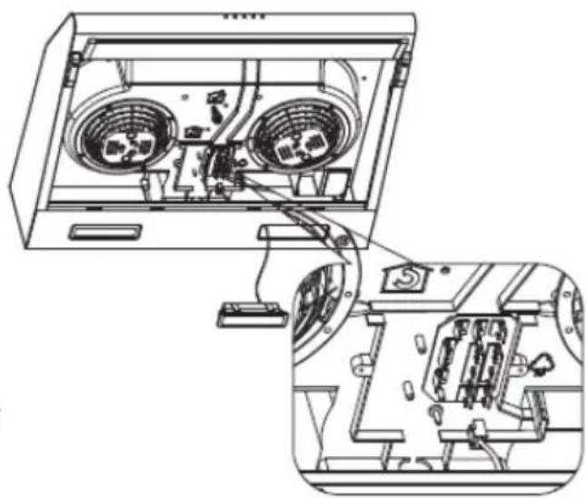
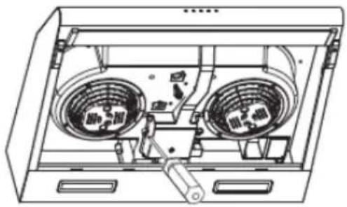
- Changing the lights
- Remove the grease filter.
- Use a screwdriver to remove the wire cover, see pic 1.
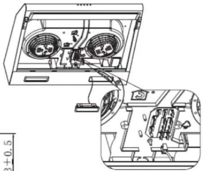
-
Put the lamp outwards by hand, remove the wire terminal to replace the lamp, see pic 2.
-
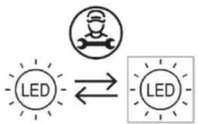
LED light replacement:LED lighting source Replaceable by professional.Warning: the LED light must not be replaced by the user! If the LED light is damaged, contact an authorized service representative for repairing.
-
Apply the reverse procedure to reinstall the light.
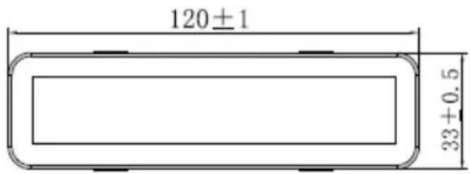
ILCOS D code for this lamp is: DBS-2/65-H-120/33
- Lamp modules -rectangle lamp
- Max wattage: 2 × 2 ~W
- Voltage range: AC 110-240V
- Dimensions:
natural_image
Technical line drawing of an air conditioner unit with two fans and a handle (no text or symbols)Pic 1

flowchart
graph LR
    A["LED"] <--> B["LED"]
natural_image
Technical line drawing of an air conditioner unit with internal components and wiring (no text or symbols)Pic 2
ENVIRONMENTAL PROTECTION

natural_image
Symbol of a trash bin crossed with no text or numbers, representing environmental restriction (no text present)This product is marked with the symbol on the selective sorting of waste electronic equipment. This means that this product must not be disposed of with household waste but must be supported by a system of selective collection in accordance with Directive 2012/19/EU. It will then be recycled or dismantled to minimize impacts on the environment, electrical and electronic products are potentially dangerous for the environment and human health due to the presence of hazardous substances. For more information, please contact your local or regional authorities.
— This appliance's packaging material is recyclable. Help recycle it and protect the environment by dropping it off in the municipal receptacles provided for this purpose.
— Your appliance also contains a great amount of recyclable material. It is marked with this label to indicate the used appliances that should not be mixed with other waste. This way, the appliance recycling organised by your manufacturer will be done under the best possible conditions, in compliance with European Directive 2002/96/EC on Waste Electrical and Electronic Equipment. Contact your town hall or your retailer for the used appliance collection points closest to your home.
— We thank you doing your part to protect the environment

NOTE :
The following shows how to reduce total environmental impact (e.g. energy use) of the cooking process).
(1) Install the cooker hood in a proper place where there is efficient ventilation.
(2) Clean the cooker hood regularly so as not to block the airway.
(3) Remember to switch off the cooker hood light after cooking.
Remember to switch off the cooker hood after cooking
● INFORMATION FOR DISMANTLING
Do not dismantle the appliance in a way which is not shown in the user manual. The appliance could not be dismantled by user. At the end of life, the appliance should not be disposed of with household waste. Check with your Local Authority or retainer for recycling advice.
7 / AFTER-SALES SERVICE
EN
Any maintenance on your equipment should be undertaken by:
- either your dealer,
-or another qualified mechanic who is an authorized agent for the brand appliances. When making an appointment, state the full reference of your equipment (model, type and serial number). This information appears on the manufacturer's nameplate attached to your equipment.
This device complies with the delegated regulations (EU) 65/2014 and 66/2014 of the European Commission on the eco design requirements and energy labeling of household hoods.
| Symbol | Value | Unit | |
| Brand | Brandt | ||
| Model number | BHC4611B-01/BHC4611W-01/BHC4611X-01 | ||
| Annual energy consumption | AEC | 58.5 | kWh/annum |
| Energy efficiency index | EEi | 83.8 | - |
| Fluid dynamic efficiency index | FDE | 9.8 | - |
| Lighting efficiency index | LE | 52.0 | - |
| Grease filtering efficiency | GFE | 55.6 | - |
| Maximum volumetric airflow of the cooker hood | Q_max | 319.1 | m^3/h |
| Volumetric airflow at best efficiency point | Q_BEP | 164.5 | m^3/h |
| Static pressure at the best efficiency point | P_BEP | 204.7 | Pa |
| Power consumption at the best efficiency point | W_BEP | 95.04 | W |
| Nominal power consumption of lighting system | W_L | 4.1 | W |
| Average illumination of the lighting system | E_middle | 212.16 | Lux/W |
| Power consumption in off mode | P_o | 0 | W |
| Power consumption in standby mode | P_s | - | W |
| Volumetric airflow at the highest speed setting in normal use | 319.1 | m^3/h | |
| Volumetric airflow at the lowest speed setting in normal use | 172.5 | m^3/h | |
| Sound power emissions at the highest speed setting in normal use | 68 | dB( L_WA ) | |
| Sound power emissions at the lowest speed setting in normal use | 58 | dB( L_WA ) | |

- Brandt
- FR 2 / INSTALLATION
- - REMPLACEMENT ET NETTOYAGE DES FILTRES À GRAISSE
- NOTE:
- • PROTECTION DE L'ENVIRONNEMENT
- ● INTERVENTIONS FRANCE
- Warning :
- CONTENTS
- EN
- Attention
- Safety and important precautions
- Electrical risks :
- Risk of asphyxiation :
- Risk of fire :
- WARNING
- EN 1 / Safety instructions
- • DESCRIPTION OF YOUR APPLIANCEL
- ● MOUNTING OF THE V-FLAP
- ● Method A: (Wall mounting)
- ● Method B (Cabinet mounting)
- / INSTALLATION
- EN 2 / INSTALLATION
- • Air ventilation setting
- EN 3 / Using your appliance
- ● Description of the control panel
- Note :
- EN 5 / MAINTENANCE AND CLEANING
- - Caution :
- GENERAL
- • STAINLESS STEEL
- • CONTROL PANEL SURFACE
- Important:
- - CHANGING AND CLEANING THE GREASE FILTERS
- - INSTALLING GREASE FILTERS
- - CARBON FILTER
- - CHANGING THE LIGHT BULB
- Important :
- - Changing the lights
- ENVIRONMENTAL PROTECTION
- ● INFORMATION FOR DISMANTLING
- / AFTER-SALES SERVICE
Brand : BRANDT
Model : BHC4611B
Category : Basket