BHC6601X - Basket BRANDT - Free user manual and instructions
Find the device manual for free BHC6601X BRANDT in PDF.

User questions about BHC6601X BRANDT
0 question about this device. Answer the ones you know or ask your own.
Ask a new question about this device
Download the instructions for your Basket in PDF format for free! Find your manual BHC6601X - BRANDT and take your electronic device back in hand. On this page are published all the documents necessary for the use of your device. BHC6601X by BRANDT.
USER MANUAL BHC6601X BRANDT
natural_image
Black-and-white photo of a bowl with leaf garnish, blurred bowls in background (no text or symbols)Hotte de Cuisine
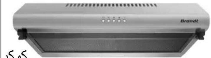
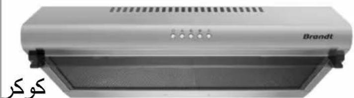
Cooker Hood
Campana de cocina
هود شفاط مطبخ
natural_image
Exterior view of a brandt air conditioner unit (no visible text or symbols on the device body)Chère Cliente, Cher Client,
5
6
7

8

9
natural_image
Technical diagram of a mechanical assembly with directional arrows indicating motion (no text or labels)natural_image
Technical diagram of a mechanical assembly with directional arrows indicating motion or force (no text or symbols)natural_image
3D diagram of a rectangular block with a circular hole labeled 'A' and a textured top surface (no text or symbols beyond the label)natural_image
Diagram of a refrigerator interior showing internal compartments and ventilation slots (no text or labels)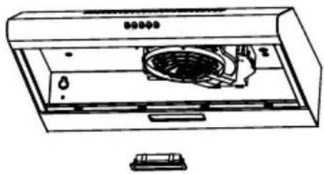
natural_image
Line drawing of an air conditioner unit with fan and vent (no text or symbols)| Max power | Voltage Picture | Lamp Cap | ILCOS D code | ||
| Module Led | 1.5W | 220-240V | 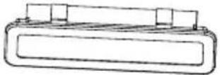 Dimensions : 33.2 mm x 120 mm Dimensions : 33.2 mm x 120 mm | ||
NETTOYAGE ET ENTRETIEN
natural_image
Line drawing of a two-door air purifier cabinet with two doors and a handle (no text or symbols)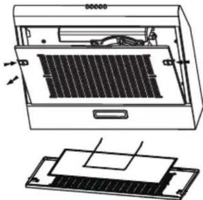
natural_image
Technical line drawing of an open air conditioner unit with internal panel and cooling cover (no text or symbols)
ATTENTION
GARANTIE ET RELATIONS CONSOMMATEURS
a) Garantie
Safety and important precautions
These instructions are also available on the web site.
Please take heed of this advice when installing and using your appliance. These instructions are intended to protect your safety and the safety of others. Keep this manual with your appliance. If you sell or give the appliance to anyone else, make sure that you also give them this manual.
- In order to constantly improve our products, we reserve the right to to make changes to their technical, functional or aesthetic characteristics in line with technological progress.
- Make a note of the references of your appliance on the "Consumer Service" page so that you can readily find them in future.
Important precautions
- This appliance is designed for use by consumers in the home. Do not use it for commercial or industrial purposes or for any other purpose for which it is not intended.
- Unpack the appliance as soon as you receive it. Check its general appearance. Make a note of any reservations on the delivery slip and keep a copy.
- This appliance can be used by children aged under 8 and by persons with diminished physical, sensory or mental capacities, or persons without any experience or knowledge, provided that they are properly attended to or are given the instructions on how to use the appliance in complete safety and that any potential risks are anticipated. Children must not play with this appliance. The appliance must not be cleaned and maintained by unattended children.
- Caution: The accessible parts of this appliance may become hot when used with cooking equipment.
Electrical risks
- All the power supply circuits must be disconnected before touching the connection terminals. If the power cord is damaged, it must be replaced by the manufacturer, its after-sales service or a similarly qualified person in order to avoid any danger.
- The appliance can be disconnected by using an accessible power outlet or by incorporating a switch in the fixed lines, in accordance with the installation rules.
- Do not change or attempt to change the characteristics of this appliance. Doing so can be dangerous.
- The appliance must only be repaired by an approved specialist.
• Always disconnect the hood before cleaning or maintaining it. - Never use steam or high-pressure tools to clean your appliance (for the purposes of electrical safety).
- Never use steam or high-pressure tools to clean your appliance (for the purposes of electrical safety).
Risk of asphyxiation
- The regulations applying to the evacuation of air must be obeyed. The air must not be sent into a duct used to evacuate fumes from appliances that use gas or other fuels (this does not apply to appliances that only emit air into the room).
- The room must be suitably ventilated when the range hood is used at the same time as appliances that use gas or other fuels (this does not apply to appliances that only emit air into the room).
Risk of fire
- It is forbidden to flambé food or to turn on gas rings that are not covered by a cooking recipient beneath the hood, as the flames may sucked in and damage the appliance.
- Keep a constant eye on fryers used beneath the hood. When heated to very high temperatures, oil and fat can catch fire.
- Clean the appliance and replace the filters at the recommended frequency. Accumulated deposits of grease can cause a fire.
- It is forbidden to use the hood above a fuel fire (wood, coal, etc.).
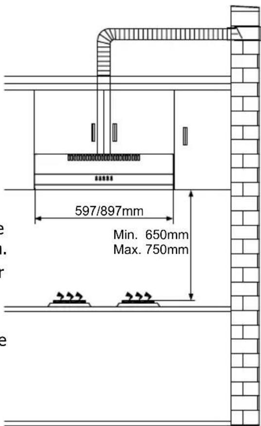
- If the hood is installed above a gas-fired appliance, leave at least 70 cm between the top of the range and the underside of the hood. If the instructions of the range installed under the hood specify a distance greater than 70 cm, then this distance must be respected.
DESCRIPTION OF THE DEVICE
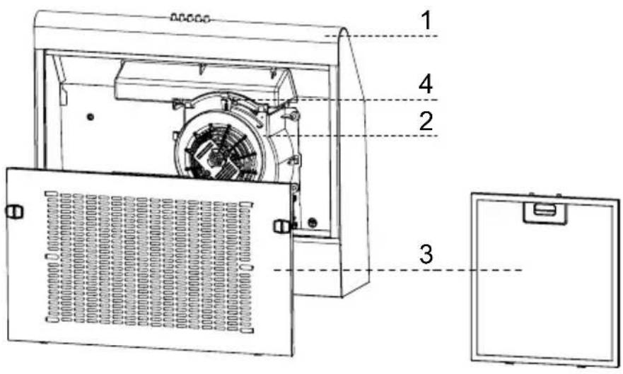
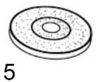
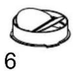
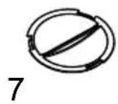
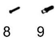
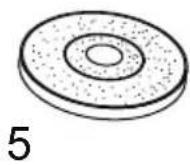
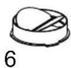
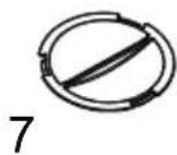
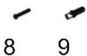
The cooker hood Other accessories:
- Air Duct Assembly 5. Carbon Filter (optional)
- Main Body 6. Check Valve (1 pcs)
- Filter Assembly (optional) 7. Air Outlet Cap (1 pcs)
- Venting Knob 8. Screws 5mm x 49mm (4 pcs)
- Plastic Wall Plugs (4 pcs)
INSTALLATION
Before installing your wall canopy:
Please read the instructions carefully.
Unpack the canopy and check that all functions are working. Ensure that the voltage (V) and the frequency (Hz) indicated on the serial plate match the voltage and frequency at the installation site.
➢ Check that the area behind the installation surface to be drilled is clear of any electrical cables or pipes, etc.
The stainless steel and glass surfaces of the canopy are very easily damaged during installation if grazed or knocked by tools. Please take care to protect the surfaces during installation.
Protect the cooktop surface below with cardboard, or the like, toprevent damage occurring whilst the wall canopy is being installed above.
The manufacturer shall not be liable for failure to observe all safety regulations in force for the correct and normal operation of electrical parts.
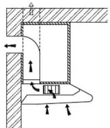
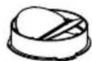
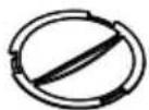
Choose a venting mode:
natural_image
Technical diagram of a mechanical assembly with directional arrows indicating motion or force (no text or symbols present)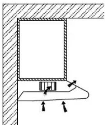
natural_image
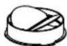
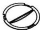
Technical diagram showing a mechanical assembly with arrows indicating motion or force direction (no text or symbols)Extraction-air mode Recirculation mode
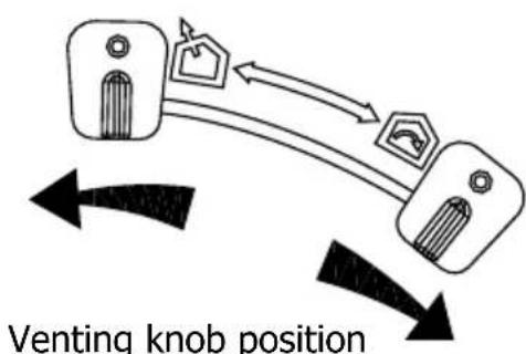
| Extraction-air mode: Turn the venting knob here means venting outside | |
| Circulating-air mode: Turn the venting knob here means recirculation |

Information
Sufficient air is needed for proper combustion and exhaustion of gases through the flue (chimney) of fuel burning equipment to prevent back drafting. Ductless fans must always be vented to the outdoors.
When assessing the air pressure, the entire ventilation system in the house/apartment must be taken into account, e.g. hob and/or gas cooker, this rule does not apply.
➢ Government regulations must be observed for the conveyance of exhaust air. If the extractor hood is used in circulating air mode with activated carbon filter, there are no operating restrictions.
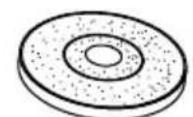
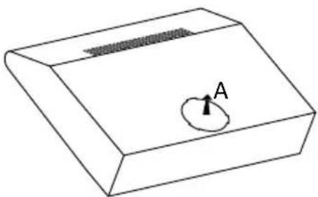
If you choose extraction-air mode, install check valve on the vent hole.
natural_image
Simple 3D diagram of a rectangular block with a circular hole labeled A, no text or symbols present.Prepare the installation:
Ensure the power has been turned off before beginning this installation. Plug must be assembled in places easy to drag and insert. To install this hood you will require two assistants. You will need following tools and material to complete this installation.
Tools you will need:
Drill appropriate to your wall
Phillips Screwdriver
Tape Measure
Hand Saw or Jig Saw
Installation work and electrical wiring must be done by qualified person(s) in accordance with all applicable codes and standards, including fire rated construction. Do not discharge the exhaust air into a flue from other appliances burning gas or other fuels. Regulations concerning the discharge of air have to be fulfilled. The cooker hood must be placed at a minimum distance of 65cm above the cooking surface of a hob.
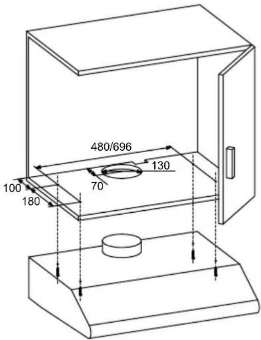
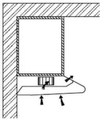
Cupboard mounting installation:
- Drill a 130mm diameter and four 3.5mm diameter hole as below picture.
ATTENTION: If your cooker hood works at circulating-air mode, it is not necessary to drill 130mm diameter hole.
- Use the 4 screws to fix the cooker hood to a kitchen cupboard .Check that your fixings are correctly located, by temporarily fitting the cooker hood. If correct, fit the unit into position. Tighten the screws if necessary.
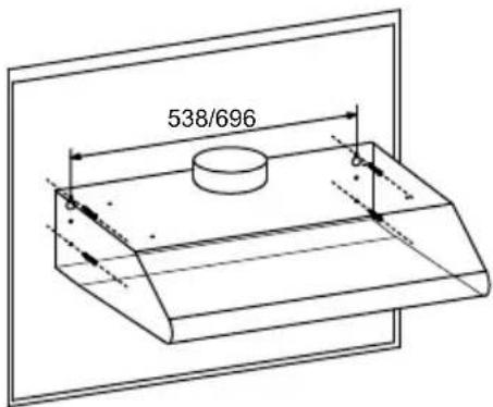
Wall mounting installation:
-
To mount on the wall, drill two 10mm diameter holes 538/696mm with the vent hole on the top of the cooker hood in the middle as below picture. Make sure the hood is aligned directly over the hob.
-
Insert two plastics wall plugs (supplied) into the holes.
-
Insert two screws into the upper two plastic wall plugs and tighten them leaving 3mm protruding from the wall.
-
Mount the cooker hood onto the two screws and mark the bottom two screw positions.
-
Remove the hood and drill the bottom two screw holes and Insert the plastic wall plugs.
-
Mount the hood on the top screws, Insert the bottom screws and fully tighten all the screws.
Information
The air must not be discharged into a flue that is used for exhausting fumes from appliances burning gas or other fuels.
OPERATION
Switch :
ON/OFF LIGHTING SWITCH: Press on this switch to
OFF MOTOR SWITCH: Press on this switch to stop the motor operation.
SPEED SWITCH: Press on this switch, the motor runs
SPEED SWITCH: Press on this switch, the motor runs at MEDIUM speed.
SPEED SWITCH: Press on this switch, the motor runs at HIGH speed.
REPLACING BULB
- Switch off the extractor hood and isolate the extractor hood by pulling out the mains plug or switching off the fuse.
- Remove the grease filter.
- Replace the lamp (commercially) led modules, separate ballast.
- Reconnect the power by inserting the mains plug or by switching on the fuse.
Max power Voltage Picture Lamp Cap ILCOS D code
Self-ballasted
LED modules
1.5W
220-240V
DBS-1.5-
H-33.2/120
Information
Clean ventilation fans frequently. Grease should not be allowed to accumulate on fan or filter.
CLEANING AND MAINTENANCE
Disconnect range hood from power supply before cleaning or servicing.
- Cleaning the surface of hood frequently. Use mild soap or detergent to clean the hood.
- Do not use harsh alkalis or abrasives.
- Avoid the use of scouring powers or dishwasher compounds.
- Grease filter may be washed using mild soap or detergent. (Heavy build-up may not be cleaned easily and the filter may require grease replacement)
- Charcoal filter cannot be cleaned and must be replaced regularly.
Information
Cleaning water must not inter into motor, control switch etc. electrical parts.
It is recommendable to clean the metallic filter every three months by carrying out the following instruction:
-
Remove the metallic filter from the cooker hood and wash it in a solution of water and neutral liquid detergent, leaving to soak.
-
Rinse thoroughly with warm water and leave to dry.
- The metallic filter may alter in color after several washes. This is not cause for customer complaint or replacement of metallic filter.
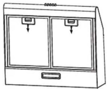
natural_image
Line drawing of a two-door air purifier cabinet with two doors and a handle (no text or symbols)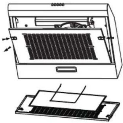
natural_image
Technical line drawing of an air conditioner unit with internal panel and base plate (no text or symbols)
Information
There is a fire risk if cleaning is not carried out in accordance with the instructions.
Installing the carbon
filter:
- Remove the grease filter
- The charcoal filter is located at end of the motor. Turn the carbon filter until it is unscrewed.
- Replace a new carbon filter, apply reverse procedure forre-installation.
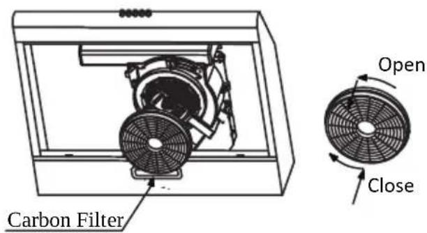
➢ Warning: the carbon filer cannot be washed or recycled. It should be replaced after approximately 2-3 months of use.
DISPOSAL

Please dispose of it at your local community waste collection / recycling center and ensure it presents no danger to children while being stored for disposal. The plug must be rendered useless and the cable cut off to prevent misuse.
Campana extractora
natural_image
Technical diagram of a mechanical assembly with directional arrows indicating motion or force (no text or symbols present)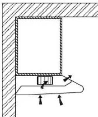
natural_image
Technical diagram showing a mechanical assembly with arrows indicating motion or force direction (no text or symbols)natural_image
Simple 3D diagram of a rectangular block with a circular hole labeled 'A' on its surface (no text or symbols beyond the label)natural_image
Technical line drawing of a refrigerator interior showing internal components and ventilation slots (no text or symbols)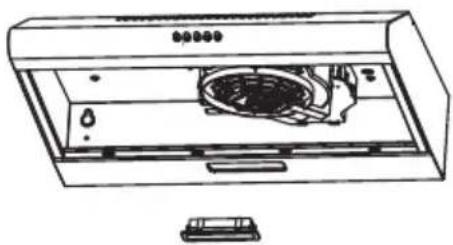
natural_image
Line drawing of a front-loading air conditioner unit with fan and control panel (no text or symbols)natural_image
Line drawing of a two-door air purifier cabinet with two doors and two outlets, no text or symbols present.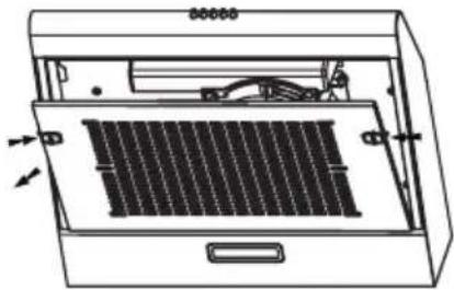
natural_image
Technical line drawing of an open refrigerator with internal panel and ventilation slots (no text or symbols)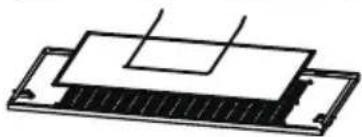
natural_image
Pure technical diagram of a layered mechanical or electronic component without any text, numbers, or symbols
Información
| Brand | Brandt | ||
| Model number | BHC6601X / BHC6601W / BHC6601B | ||
| Annual energy consumption AEC 48.0 kWh/annum | |||
| Energy efficiency index EEi 79.6 - | |||
| Fluid dynamic efficiency index FDE 9.8 - | |||
| Lighting efficiency index LE 28 - | |||
| Grease filtering efficiency GFE 77.6 - | |||
| Time increase factor | f | 1.6 - | |
| Maximum volumetric airflow of the cooker hood | Q_max | 197.7 | m^3/h |
| Volumetric airflow at best efficiency point Q | _BEP | 110.1 | m^3/h |
| Static pressure at best efficiency point | P_BEP | 256 | P |
| Power consumption at best efficiency point | W_BEP | 80.0 | W |
| Nominal power consumption of lighting system | W_L | 1.5 W | |
| Average illumination of the lighting system | E_middle | 51 Lux/W | |
| Power consumption in off mode | P_o | 0.00 W | |
| Power consumption in stanby mode | P_s | - | W |
| Volumetric airflow at the highest speed setting in normal use | - | 197.7 | m^3/h |
| Volumetric airflow at the lowest speed setting in normal use | - | 118.8 | m^3/h |
| Volumetric airflow in intensive or boost mode | - | - | m^3/h |
| Sound power emissions at the highest speed setting in normal use | - | 63 dB (L | _WA ) |
| Sound power emissions at the lowest speed setting in normal use | - | 51 dB (L | _WA ) |
| Sound power emissions in intensive/boost mode | - | - | dB ( L_WA ) |
natural_image
Diagram of a refrigerator interior showing internal components and ventilation slots (no text or labels)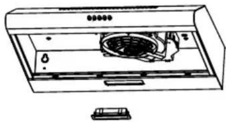
natural_image
Line drawing of a front-loading air conditioner unit with fan and cooling unit (no text or symbols)تغير霏ية
natural_image
Simple 3D diagram of a rectangular block with a circular hole labeled 'A' on its surface (no text or symbols beyond the label)natural_image
Technical diagram of a mechanical assembly with directional arrows indicating motion (no text or symbols)وضع إخراج الهواء
natural_image
Technical diagram showing a mechanical assembly with arrows indicating motion or force direction (no text or symbols present)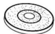
5
6
7
8

9
: Achre i kssuorat
natural_image
Black-and-white photo of a bowl with leaf garnish, blurred bowls in background (no text or symbols)Hotte de Cuisine
Cooker Hood
Campana de cocina
هود شفاط مطبخ