
BHI1944IX - Range hood BRANDT - Free user manual and instructions
Find the device manual for free BHI1944IX BRANDT in PDF.
| Product type | Range hood |
| Brand | Brandt |
| Model | BHI1944IX |
| Energy class | A (EEI = 44.8) |
| Annual energy consumption | 26.7 kWh/year |
| Maximum airflow rate | 536.4 m³/h |
| Minimum airflow rate | 186.7 m³/h |
| Pressure at maximum efficiency point | 283 Pa |
| Maximum noise level | 65 dB(A) |
| Minimum noise level | 44 dB(A) |
| Lighting | LED 7.2 W, illuminance 222 lux/W |
| Number of speeds | 3 (minimum, medium, maximum) |
| Control type | Touch (5 buttons) |
| Grease filter | Washable metal (dishwasher safe) |
| Activated carbon filter | Replaceable, not washable, lifespan ~4 months |
| Minimum installation height (above a gas hob) | 70 cm |
| Weight (estimated) | ~30 kg |
| Power supply | 230V / 50Hz (not specified, standard) |
| Safety | Omnipolar disconnection device; disconnect before maintenance |
| Recycling | Recyclable materials, WEEE logo |
| After-sales service | 0892 02 88 01 (€0.50/min + call charges) |
Frequently Asked Questions - BHI1944IX BRANDT
User questions about BHI1944IX BRANDT
0 question about this device. Answer the ones you know or ask your own.
Ask a new question about this device
Download the instructions for your Range hood in PDF format for free! Find your manual BHI1944IX - BRANDT and take your electronic device back in hand. On this page are published all the documents necessary for the use of your device. BHI1944IX by BRANDT.
USER MANUAL BHI1944IX BRANDT
EN GUIDE TO INSTALLATION
FR GUIDE D'UTILISATION
SE GUIDE FÖR INSTALLATION
- Safety recommendations ____ 4
• Environmental protection 9
• Description of your appliance 10
2 / INSTALLING YOUR APPLIANCE
- Installing your cooker hood 11
3 / USING YOUR APPLIANCE
• To use your cooker hood 13
4 / CARING FOR AND CLEANING YOUR APPLIANCE
- Changing and cleaning the anti-grease filters 14
- Changing the light bulb 14
• Install the T-Sharp outelt 14 - Maintaining your appliance 15
5 / TROUBLESHOOTING 16
6 / AFTER-SALES SERVICE 16
As part of our commitment to constantly improving our products, we reserve the right to make changes to them based on technical advances to their technical and functional features and appearance.

Warning:
Before installing and using your appliance, please carefully read this Guide to Installation and Use, which will allow you to quickly familiarise yourself with its operation.
EN
1 / NOTICES TO THE USER

Attention
Keep this user guide with your appliance. If the appliance is ever sold or transferred to another person, ensure that the new owner receives the user guide. Please become familiar with these recommendations before installing and using your appliance. They were written for your safety and the safety of others.
Safety and important precautions

These instructions are also available on the Brandt web site.
Please take heed of this advice when installing and using your appliance.
- In order to constantly improve our products, we reserve the right to make changes to their technical, functional or aesthetic characteristics in line with technological progress.
- Make a note of the references of your appliance on the "Consumer Service" page so that you can readily find them in the future.
1 / NOTICES TO THE USER EN
Important precautions
- This appliance is designed for use by consumers at home. Do not use it for commercial or industrial purposes or for any other purpose for which it is not intended.
- Unpack the appliance as soon as you receive it. Check its general appearance. Make a note of any reservations on the delivery slip and keep a copy.
- This appliance can be used by children aged under 8 and by persons with diminished physical, sensory or mental capacities, or persons without any experience or knowledge, provided that they are properly attended to or are given the instructions on how to use the appliance in complete safety and that any potential risks are anticipated. Children must not play with this appliance. The appliance must not be cleaned and maintained by unattended children.
- Caution: The accessible parts of this appliance may become hot when used with cooking equipment.
Electrical risks
- All the power supply circuits must be disconnected before touching the connection terminals. If the power cord is damaged, it must be
1 / NOTICES TO THE USEREN
replaced by the manufacturer, its after-sales service or a similarly qualified person in order to avoid any danger.
- The appliance can be disconnected by using an accessible power outlet or by incorporating a switch in the fixed lines, in accordance with the installation rules.
- Do not change or attempt to change the characteristics of this appliance. Doing so can be dangerous.
- The appliance must only be repaired by an approved specialist.
• Always disconnect the hood before cleaning or maintaining it. - Never use steam or high-pressure tools to clean your appliance (for the purposes of electrical safety).
1 / NOTICES TO THE USER EN
Risk of asphyxiation
- The regulations applying to the evacuation of air must be obeyed. The air must not be sent into a duct used to evacuate fumes from appliances that use gas or other fuels (this does not apply to appliances that only emit air into the room).
- The room must be suitably ventilated when the range hood is used at the same time as appliances that use gas or other fuels (this does not apply to appliances that only emit air into the room).
Risk of fire
- It is forbidden to flame food or to turn on gas rings that are not covered by a cooking recipient beneath the hood, as the flames may be sucked in and damage the appliance.
- Keep a constant eye on fryers used beneath the hood. When heated to very high temperatures, oil and fat can catch fire.
- Clean the appliance and replace the filters at
1 / NOTICES TO THE USEREN
the recommended frequency. Accumulated deposits of grease can cause a fire.
- It is forbidden to use the hood above a fuel fire (wood, coal, etc.).
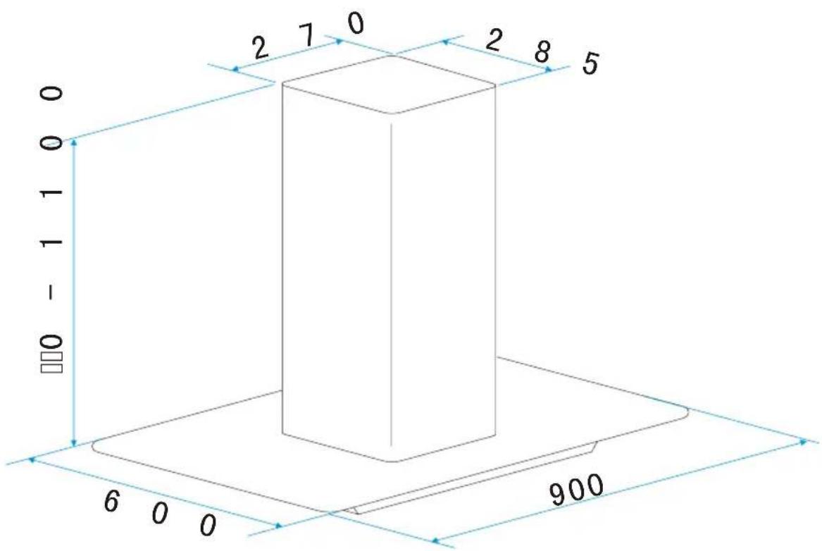
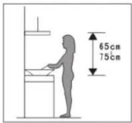
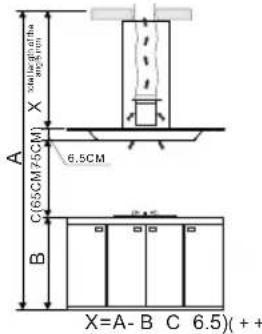
- If the hood is installed above a gas-fired appliance, leave at least 70 cm between the top of the cooker and the underside of the hood. If the instructions of the cooker installed under the hood specify a distance greater than 70 cm, then this distance must be respected.

Warning
In the case of a kitchen heated by a device connected to a chimney (a stove, for example) the "recycling" version of the hood should be installed. Do not use the hood without metal filters.
Suitable ventilation should be provided in the room when the hood is used at the same time as appliances operated by gas or another combustible fuel.
1 / NOTICES TO THE USER EN
• ENVIRONMENTAL PROTECTION
— This appliance's packaging material is recyclable. Help recycle it and protect the environment by dropping it off in the municipal receptacles provided for this purpose.
- Your appliance also contains a great amount of recyclable material. It is marked with this label to indicate the used appliances that should not be mixed with other waste. This way, the appliance recycling organised by your manufacturer will be done under the best possible conditions, in compliance with European Directive 2002/96/EC on Waste Electrical and Electronic Equipment. Contact your town hall or your retailer for the used appliance collection points closest to your home.
— We thank you doing your part to protect the environment.

Warning
Installation should only be performed by installers and qualified technicians.

Warning
Remove the protective fi lm from the cartridge fi iter before use.
1 / NOTICES TO THE USEREN
• DESCRIPTION OF YOUR APPLIANCE
2 / INSTALLING YOUR APPLIANCE EN
• INSTALLING YOUR COOKER HOOD
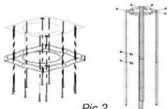
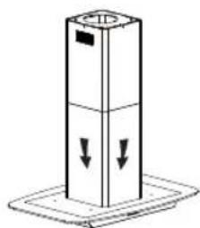
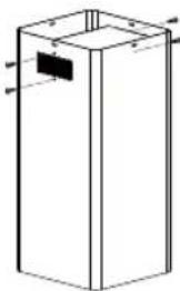
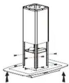
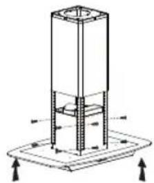
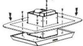
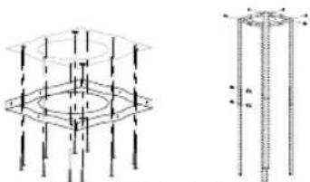
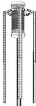
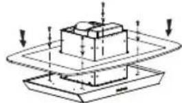
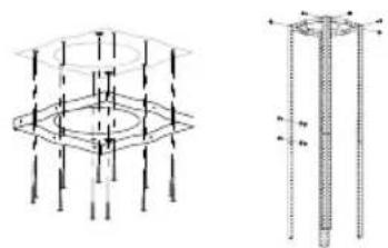
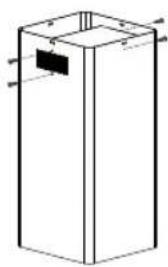
— The ceiling must be able to bear at least 40kgs weight, and the thickness of the ceiling must be ≥30MM, see pic 2, drill 1*170mm round hole in the ceiling.
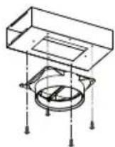
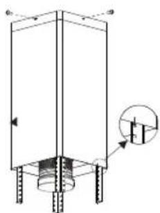
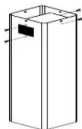
- According to the hanging board, drill 12 holes in the ceiling, see pic 2, 12pcs of ST6*40mm big flat screws will be used to fix the hanging board on the ceiling, and then 8pcs of M4*10 screws and M4 nut with gasket will be used to connect the angle iron into the hanging board. See pic 1. Calculate the length of the angle iron, and use 16 pcs of M4*10 big flat screws and M4 nuts with gasket to connect the angle iron to the other angle iron (the overlap length of the angle iron cannot be less than 100 mm).
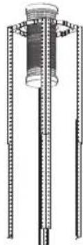
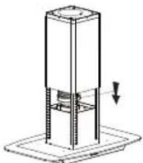
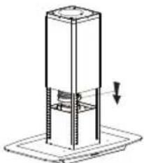
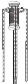
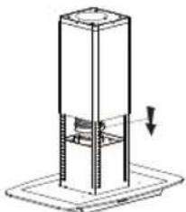
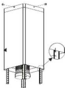
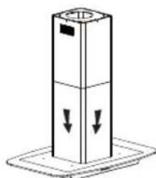
— Let the one side of the extensible pipe go outside through the hole of 170MM, see pic 3.
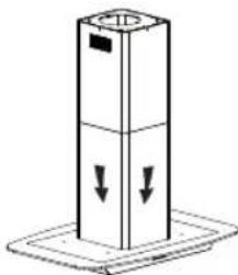
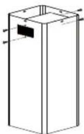
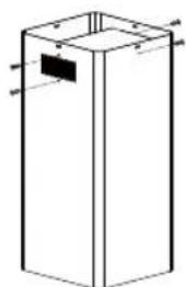
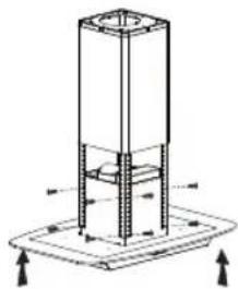
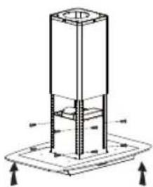
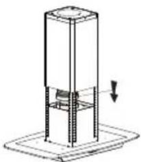
— 4pcs ST4*8 big flat screws will be used to connect the internal chimney into the hanging board, then put one the external chimney, two hooks will be used to put up the external chimney in order to the next installation, see pic 4.
Pic 1
natural_image
Technical diagram showing a 3D structural assembly with vertical supports and a detailed cross-sectional view of a cylindrical component (no text or labels)Pic 2
natural_image
Technical line drawing of a vertical cylindrical device with three vertical supports and a central cylindrical component (no text or symbols)Pic 3

natural_image
Technical line drawing of a vertical structural frame with a magnified inset showing internal components (no text or symbols)Pic 4
EN 2 / INSTALLING YOUR APPLIANCE
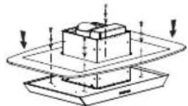
— Mount the V-flap to the air outlet
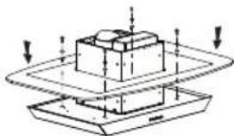
— Adjust the 4 glass screws to check whether the glass and the cooker hood body are connected well and fixed, see pic 6.
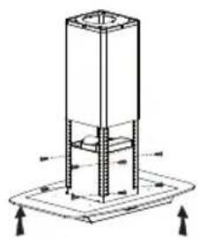
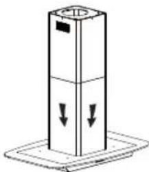
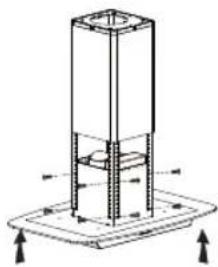
— Hold up the hood, 16pcs M4*10 big flat screws will be used to connect the hood body into angle iron, see pic 7.
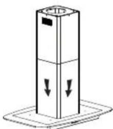
— Put the extensible pipe on the outlet. After making sure that everything is ok, put down the hook, see pic 8.

Advice on how to save energy
To make optimal use of your appliance, keep the length of the duct and the number of bends in the duct to a strict minimum.

Note
— Before installation, please ensure the area is clean to avoid suction of the remaining bits of broken wood and dust.
— It cannot share the same air ventilation tube with other appliance such as gas tube, warmer tube, and hot wind tube.
— The bending of ventilation tube should be ≤ 120^ , parallel or above the start point and should be connected to the external wall.
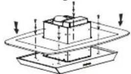
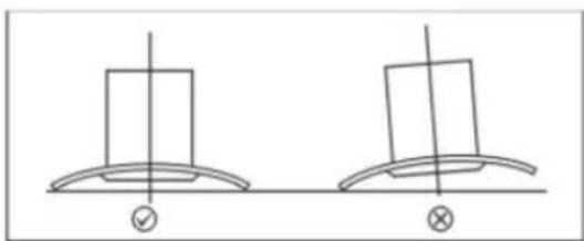
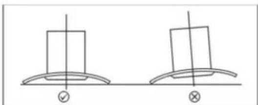
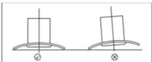
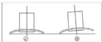
— After installation, make sure that the extractor is leveled to avoid grease collection at one end. See Pic 10.
natural_image
Technical line drawing of a satellite dish with an inset showing its internal structure (no text or symbols)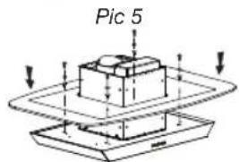
Pic 6

natural_image
Technical line drawing of a mechanical assembly with no visible text or symbolsPic 7
natural_image
Technical line drawing of a cylindrical mechanical device with a base and internal components, showing a downward force arrow (no text or symbols)Pic 8
natural_image
Simple line drawing of a vertical cylindrical object with downward arrows, placed on a base (no text or symbols)Pic 9

natural_image
Two identical 3D diagrammatic shapes resembling a tower or hat with crosshair indicators, no text or symbols present.Pic 10
3 / USING YOUR APPLIANCE EN
• TO USE YOUR COOKER HOOD
How to use the control panel, See Pic 11.
- Press the button “①”, its inner indicator lights bright, the motor runs at low speed and its indicator lights bright. Press the button “①” again, the indicators light will be off. All the function of the hood will be closed, the hood enters into standby mode.
- Press the button "1", its inner indicator lights bright, the motor is running at low speed. Press the button again, the motor stops.
- Press the button "2", its inner indicator lights bright, the motor is running at medium speed. Press the button again, the motor stops.
- Press the button "3", its inner indicator lights bright, the motor is running at high speed. Press the button again, the motor stops.
- Press the button " 🔍", both spot lights start bright. Press the button again, the lights will be switched off.

Advice on how to save energy
Adjust the speed to the cooking method and the number of pans in use. It is preferable to use the rings at the back of the range.

EN 4 / CARING FOR AND CLEANING YOUR APPLIANCE
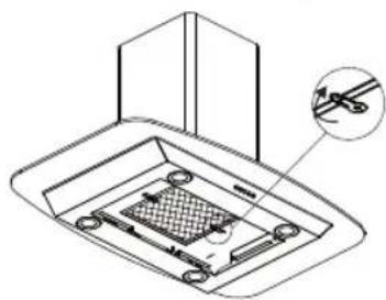
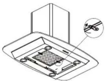
- CHANGING AND CLEANING THE ANTI-GREASE FILTERS
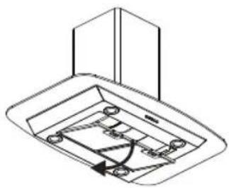
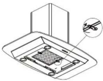
— Removing the filters as the instruction in Pic. 12
— You can clean the filter as below measure:
- Soak them for about 3 minute in hot water (40-50 degrees) with a grease-loosening detergent then brush it gently with a soft brush. Please do not apply too much pressure, avoid damaging it.
— Please do not use abrasive detergent for it will damage the hood;
— Make sure that the hood is shut off before cleaning;
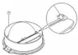
— Installing the carbon filter:
-
Remove the AI filter, see Pic.12
-
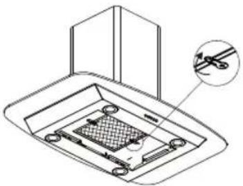
Insert the carbon filter in the rectangular hole, fitting it over the motor.
-
After inserting the front edge of the carbon filter into the slot on the cooker hood. Lower the back edge of the carbon filter, until it clicks into place at the rear of the rectangular hole. Raise the two fixing bars, until they are horizontal over the carbon filter. See Pic 13
-
Place the Al. filter back to position.
-
Apply reverse procedure to uninstall the carbon filter.

Warning
the charcoal cannot be washed or recycled. It should be changed at least every four months.
• CHANGING THE LIGHT BULB
The lighting system cannot be replaced by the user, contact Customer Service in case of malfunction.
• INSTALL THE T-SHARP OUTELT
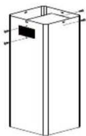
— Fix the outlet outlet on the T-sharp, see Pic 14.
— Fix the T-sharp outlet on the inside chimney, see Pic 15.
natural_image
Technical line drawing of a ceiling-mounted device with mounting holes and internal components (no text or symbols)Pic 12
natural_image
Technical line drawing of a ceiling-mounted device with a magnified inset showing internal components (no text or symbols)Pic 13
Pic 14
natural_image
Isometric line drawing of a rectangular box with a small black label on the side (no text or symbols)Pic 15
4 / CARING FOR AND CLEANING YOUR APPLIANCE EN

Warning
Before carrying out any work, the power supply to the hood must be turned off, either by unplugging it or by using the circuit breaker switch.
• MAINTAINING YOUR APPLIANCE
| MAINTENANCE WHAT TO DO | PRODUCTS / ACCESSORIES TO USE | |
| Top surface and accessories | Never use metal scouring pads, abrasive products or excessively stiff brushes. | To clean the body and the lighting port, you should use only commercial household cleaning products diluted in water and then rinse using clean water, drying with a soft cloth. |
| Filter cartridge | This fi lter traps fatty vapours and dust. This component plays an important role in ensuring the effectiveness of your hood. In the event of tough stains, use a non-abrasive cream, then rinse with clean water. | Use a commercial household cleaning product then rinse abundantly and dry. These fi Iters can be cleaned in a vertical position in your dishwasher.(Do not allow them to touch dirty dishes or silverware.) |
| Activated carbon fi lter | This fi lter traps odours and must be changed at least once a year depending on your level of use. You should order these fi Iters from your dealer (quoting the reference shown on the identifi cation plate located inside the hood) and note the date the fi lter was changed. | |
5 / TROUBLESHOOTINGEN
| SYMPTOMS | SOLUTIONS |
| The hood is not working... | Ensure that:• The power is not cut off.• A speed has been selected. |
| The hood is not operating effectively... | Ensure that:• The selected motor speed is suffi cient for the quantity of smoke and vapours to be cleared.• The kitchen is suffi ciently ventilated to allow for fresh air intake.• The carbon fi Iter is not worn (hood operating in recycling mode). |
| The hood stopped working | Ensure that:• The power is not cut off.• The single-pole cut-off device was not activated. |
6 / AFTER-SALES SERVICEEN
Any maintenance on your equipment should be undertaken by:
- either your dealer,
- or another qualified mechanic who is an authorized agent for the brand appliances.
When making an appointment, state the full reference of your equipment (model, type and serial number). This information appears on the manufacturer's nameplate attached to your equipment.
Ecodesign information / Technical product fiche
EN
This device complies with the delegated regulations (EU) 65/2014 and 66/2014 of the European Commission on the eco design requirements and energy labeling of household hoods.
symbol Value Unit
| Brand | Brandt | ||
| Model number | BHI1944IX | ||
| Annual energy consumption | AEC | 26,7 | kWh/annum |
| Energy efficiency index | EEi | 44,8 | - |
| Fluid dynamic efficiency index | FDE | 32,7 | - |
| Lighting efficiency index | LE | 30,8 | - |
| Grease filtering efficiency | GFE | 82,0 | - |
| Time increase factor | f | 0,8 | - |
| Maximum volumetric airflow of the cooker hood | Q_max | 536,4 | m^3/h |
| Volumetric airflow at best efficiency point | Q_BEP | 305,5 | m^3/h |
| Static pressure at the best efficiency point | P_BEP | 283 | P |
| Power consumption at the best efficiency point | W_BEP | 73,4 | W |
| Nominal power consumption of lighting system | W_L | 7,2 | W |
| Average illumination of the lighting system | E_middle | 222 | Lux/W |
| Power consumption in off mode | P_o | -- | W |
| Power consumption in standby mode | P_s | 0,34 | W |
| Volumetric airflow at the highest speed setting in normal use - | 536,4 | m^3/h | |
| Volumetric airflow at the lowest speed setting in normal use - | 186,7 | m^3/h | |
| Volumetric airflow in intensive or boost mode - | -- | m^3/h | |
| Sound power emissions at the highest speed setting in normal use - | 65 | dB(LwA) | |
| Sound power emissions at the lowest speed setting in normal use - | 44 | dB(LwA) | |
| Sound power emissions in intensive / boost mode - | -- | dB(LwA) | |
FR\$
1 / A L'ATTENTION DE L'UTILISATEUR
natural_image
Technical diagram showing a 3D structural assembly with vertical supports and a detailed cross-section of a cylindrical component (no text or symbols present)
natural_image
Technical line drawing of a cylindrical mechanical component with vertical supports and a central cylindrical shaft (no text or symbols)Image 3
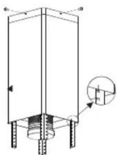
Image 4
2 / INSTALLATION DE L'APPAREILFR
natural_image
Technical line drawing of a mechanical assembly with a dome component and a magnified inset showing a pin inserted into a housing (no text or symbols)Image 5
natural_image
Diagram of a mechanical assembly with downward arrows indicating force or movement (no text or symbols)Image 6
natural_image
Technical diagram of a mechanical assembly with a cylindrical component and mounting base (no text or symbols)Image 7
natural_image
Technical line drawing of a cylindrical mechanical device with a base and internal structure, showing no text or symbols.Image 8

natural_image
Simple line drawing of a vertical cylindrical object with downward arrows, placed on a base (no text or symbols)Image 9

natural_image
Two identical line drawings of a top hat with crosshair indicators, no text or symbols present.Image 10
3 / MODE D'EMPLOI FR
• UTILISATION DE LA HOTTE ASPIRANTE
natural_image
Technical line drawing of a mechanical assembly with no visible text or symbolsImage 12

natural_image
Technical line drawing of a mechanical component with a magnified inset showing a detail (no text or symbols)Image 13

Image 14
natural_image
Simple line drawing of a rectangular box with a small black label on the side (no text or symbols)Image 15
4 / NETTOYAGE ET ENTRETIEN DE L'APPAREIL FR

Attention :
1- RELATIONS CONSOMMATEURS FRANCE
Imagem 1

natural_image
Technical line drawing of a mechanical assembly with cross-sectional and top views (no text or symbols)Imagem 2
natural_image
Technical line drawing of a vertical cylindrical device with multiple vertical supports and a central cylindrical component (no text or symbols)Imagem 3
natural_image
Technical line drawing of a vertical structural frame with base and supports, showing internal components and an inset detail (no text or symbols)Imagem 4
natural_image
Technical line drawing of a satellite or spacecraft with an inset showing its internal structure (no text or symbols)Imagem 5

natural_image
Diagram of a mechanical assembly with layered components and directional arrows (no text or symbols)Imagem 6
natural_image
Technical diagram of a cylindrical mechanical assembly with mounting base and support frame (no text or symbols)Imagem 7

natural_image
Technical line drawing of a cylindrical mechanical component with a downward arrow indicating force or motion (no text or symbols)Imagem 8

natural_image
Simple line drawing of a vertical cylindrical object with downward arrows, placed on a base (no text or symbols)Imagem 9
natural_image
Two identical top hat designs with crosshair indicators, no text or symbols presentImagem 10
natural_image
Technical line drawing of a ceiling-mounted fixture with mounting bracket and internal components (no text or symbols)Imagem 12
natural_image
Technical line drawing of a mechanical component with a magnified inset showing a tool interacting with it (no text or symbols present)Imagem 13

Imagem 14
natural_image
Simple line drawing of a rectangular box with a small rectangular cutout on top (no text or symbols)Imagem 15
4 / CUIDADO E LIMPEZA DO SEU APARELHO PT

Advertência
natural_image
Technical line drawing of a vertical cylindrical device with internal components and mounting brackets (no text or symbols)Abbildung 3

natural_image
Technical line drawing of a vertical structural frame with a circular inset detail (no text or symbols)Abbildung 4
2 / INSTALLATION DES GERÄTSDE
natural_image
Technical line drawing of a satellite dish with an inset showing its internal structure (no text or symbols)Abbildung 5
natural_image
Diagram of a mechanical assembly with layered components and directional arrows (no text or symbols)Abbildung 6

natural_image
Technical diagram of a mechanical assembly with a cylindrical component and mounting base (no text or symbols)Abbildung 7
natural_image
Technical line drawing of a cylindrical mechanical component with a downward arrow indicating force or motion (no text or symbols)Abbildung 8
natural_image
Simple line drawing of a vertical cylindrical object with downward arrows, placed on a base (no text or symbols)Abbildung 9

natural_image
Two identical line drawings of a top hat with crosshair indicators, no text or symbols present.Abbildung 10
natural_image
Technical line drawing of a ceiling-mounted electrical enclosure with mounting holes and wiring (no text or symbols)Abbildung 12
natural_image
Technical line drawing of a ceiling-mounted device with a close-up inset showing a tool interacting with the component (no text or symbols present)Abbildung 13
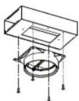
Abbildung 14
natural_image
Simple line drawing of a rectangular box with a small black label on the side (no text or symbols)Abbildung 15
2 / INSTALACE VAŠEHO PŘÍSTROJE
- Instalace Vašeho odsavače 74
3 / POUŽITÍ VAŠEHO PŘÍSTROJE
2 / INSTALACE VAŠEHO PŘÍSTROJE
CZ
• INSTALACE VAŠEHO ODSAVAČE
Obrázek 1
natural_image
Technical line drawing of a mechanical assembly with cross-sectional and top views (no text or symbols)Obrázek 2
natural_image
Technical line drawing of a vertical cylindrical device with multiple vertical supports and a central cylindrical component (no text or symbols)Obrázek 3
natural_image
Technical line drawing of a vertical structural frame with mounting feet and a circular inset detail (no text or symbols)Obrázek 4
CZ 2 / INSTALACE VAŠEHO PŘÍSTROJE
natural_image
Technical line drawing of a satellite dish with an inset showing its internal structure (no text or symbols)Obrázek 5
natural_image
Diagram of a mechanical assembly with downward arrows indicating motion or force, no text or symbols presentObrázek 6
natural_image
Technical line drawing of a mechanical assembly with no visible text or symbolsObrázek 7

natural_image
Technical line drawing of a vertical cylindrical device with a base and arrow indicating downward motion (no text or symbols)Obrázek 8
natural_image
Simple line drawing of a vertical cylindrical object with downward arrows, resting on a base (no text or symbols)Obrázek 9
natural_image
Two identical line drawings of a top hat with crosshair indicators, no text or symbols present.Obrázek 10
3 / POUŽITÍ VAŠEHO PŘÍSTROJE
CZ
- POUŽITÍ VAŠEHO KUCHYŇSKÉHO OSAVAČE
natural_image
Technical line drawing of a ceiling-mounted electrical cabinet with internal components (no text or symbols)Obrázek 12
natural_image
Technical line drawing of a mechanical component with a magnified inset showing a detail (no text or symbols)Obrázek 13

Obrázek 14
natural_image
Simple line drawing of a rectangular box with a small rectangular cutout and two side handles (no text or symbols)Obrázek 15
4 / ÚDRŽBA A ČIŠTĚNÍ VAŠEHO PRÍSTROJE
CZ

Varování
- ÚDRŽBA VAŠEHO PŘÍSTROJE
2 / INSTALLATION AF APPARATET
natural_image
Technical line drawing of a structural column with internal supports and cross-section details (no text or symbols)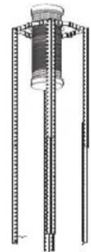
natural_image
Technical line drawing of a mechanical assembly with vertical rods and a central cylindrical component (no text or symbols)Illustration 3

natural_image
Technical line drawing of a vertical structural component with mounting feet and a magnified inset showing internal detail (no text or symbols)Illustration 4
2 / INSTALLATION AF APPARATETDK
natural_image
Technical line drawing of a satellite dish with an inset showing its internal structure (no text or symbols)Illustration 5
natural_image
Diagram of a mechanical assembly with downward arrows indicating force or movement (no text or symbols)Illustration 6
natural_image
Technical diagram of a vertical cylindrical structure mounted on a base plate, with directional arrows indicating force or movement (no text or symbols present)Illustration 7

natural_image
Technical line drawing of a cylindrical mechanical component with a downward arrow indicating force or motion (no text or symbols)Illustration 8
natural_image
Simple line drawing of a vertical cylindrical object with downward arrows, placed on a base (no text or symbols)Illustration 9
natural_image
Two identical line drawings of a top hat with crosshair indicators, no text or symbols presentIllustration 10
3 / BRUG AF APPARATET DK
• BRUG AF EMHÆTTEN
DK 4 / PLEJE OG RENG∅RING AF APPARATET
• UDSKIFTNING OG RENG∅RING AF ANTI-FEDT FILTRENE
—Afmonter filtrene som vist på Illustration 12.
— Filtret kan rengøres som beskrevet herunder:
natural_image
Technical line drawing of a ceiling-mounted device with mounting holes and a curved arrow indicating rotation (no text or symbols)Illustration 12

natural_image
Technical line drawing of a mechanical component with a magnified inset showing a tool interacting with a grid-patterned base (no text or symbols)Illustration 13
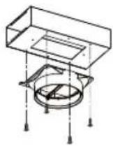
Illustration 14

natural_image
Simple line drawing of a rectangular box with a small black tab on top (no text or symbols)Illustration 15
4 / PLEJE OG RENG∅RING AF APPARATET DK

Advarsel
INNEHÅLLSFÖRTECKNING
SE
1 / INFORMATION TILL ANVÄNDAREN
natural_image
Technical line drawing of a vertical cylindrical structure with mounting feet and a magnified inset showing internal detail (no text or symbols)Bild.4
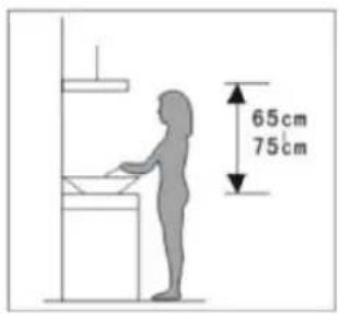
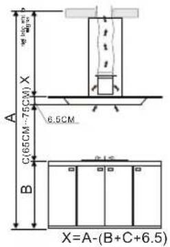
Bild. 1
natural_image
Technical line drawing of a structural framework with vertical supports and a 3D cross-section view (no text or symbols)Bild.2

natural_image
Technical line drawing of a mechanical component with three vertical rods and a central cylindrical shaft (no text or symbols)Bild.3
SE
2 / INSTALLERA DIN APPARAT
- Montera V-klaffen på luftutloppet
natural_image
Technical line drawing of a mechanical component with an inset view showing a magnified detail (no text or symbols)Bild.5
natural_image
Diagram of a mechanical assembly with layered components and directional arrows (no text or labels)Bild.6
natural_image
Technical line drawing of a mechanical assembly with no visible text or symbolsBild.7

natural_image
Technical line drawing of a mechanical assembly with a cylindrical component and base, showing a downward force arrow (no text or symbols)Bild.8

natural_image
Simple line drawing of a vertical cylindrical object with downward arrows, placed on a base (no text or symbols)Bild.9
natural_image
Two identical 3D geometric shapes with crosshair indicators, no text or symbols presentBild.10
natural_image
Technical line drawing of a ceiling-mounted electrical enclosure with internal components and a directional arrow indicating rotation (no text or symbols)Bild.12

natural_image
Technical line drawing of a mechanical component with a magnified inset showing a tool interacting with a grid-patterned base (no text or symbols)Bild.13
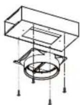
Bild.14
natural_image
Simple line drawing of a rectangular box with a small black label on the side (no text or symbols)Bild.15
4 / RENGÖRING OCH UNDERHÅLL FÖR DIN APPARAT
SE

Varning
natural_image
Technical diagram of a vertical structural component with mounting feet and internal structure (no text or symbols)Eik.4
natural_image
Technical line drawing of a mechanical assembly with a dome and gear mechanism (no text or symbols)Eik.5

natural_image
Diagram of a mechanical assembly with layered components and directional arrows (no text or labels)Eik.6
natural_image
Technical line drawing of a mechanical assembly with no visible text or symbolsEik.7
natural_image
Technical line drawing of a mechanical assembly with a cylindrical component and base plate (no text or symbols)Eik.8
natural_image
Simple line drawing of a vertical cylindrical object with downward arrows, placed on a base (no text or symbols)Eik.9

natural_image
Two identical 3D geometric shapes with crosshair indicators, no text or symbols presentEik.10
natural_image
Technical line drawing of a mechanical component with a magnified inset showing a tool interacting with a grid-patterned base (no text or symbols)Eik.13
GR
natural_image
Simple line drawing of a rectangular box with a small rectangular cutout and two arrows pointing to the sides (no text or symbols)Eik.15


- / INSTALLING YOUR APPLIANCE
- / USING YOUR APPLIANCE
- / CARING FOR AND CLEANING YOUR APPLIANCE
- Warning:
- EN
- / NOTICES TO THE USER
- Attention
- Safety and important precautions
- / NOTICES TO THE USER EN
- Important precautions
- Electrical risks
- / NOTICES TO THE USEREN
- Risk of asphyxiation
- Risk of fire
- Warning
- • ENVIRONMENTAL PROTECTION
- / INSTALLING YOUR APPLIANCE EN
- • INSTALLING YOUR COOKER HOOD
- EN 2 / INSTALLING YOUR APPLIANCE
- Advice on how to save energy
- Note
- / USING YOUR APPLIANCE EN
- • TO USE YOUR COOKER HOOD
- EN 4 / CARING FOR AND CLEANING YOUR APPLIANCE
- - CHANGING AND CLEANING THE ANTI-GREASE FILTERS
- • CHANGING THE LIGHT BULB
- • INSTALL THE T-SHARP OUTELT
- / CARING FOR AND CLEANING YOUR APPLIANCE EN
- / TROUBLESHOOTINGEN
- / AFTER-SALES SERVICEEN
- Ecodesign information / Technical product fiche
- FR\$
- / A L'ATTENTION DE L'UTILISATEUR
- / INSTALLATION DE L'APPAREILFR
- / MODE D'EMPLOI FR
- • UTILISATION DE LA HOTTE ASPIRANTE
- / NETTOYAGE ET ENTRETIEN DE L'APPAREIL FR
- Attention :
- 1- RELATIONS CONSOMMATEURS FRANCE
- / CUIDADO E LIMPEZA DO SEU APARELHO PT
- Advertência
- / INSTALLATION DES GERÄTSDE
- / INSTALACE VAŠEHO PŘÍSTROJE
- / POUŽITÍ VAŠEHO PŘÍSTROJE
- • INSTALACE VAŠEHO ODSAVAČE
- CZ 2 / INSTALACE VAŠEHO PŘÍSTROJE
- - POUŽITÍ VAŠEHO KUCHYŇSKÉHO OSAVAČE
- / ÚDRŽBA A ČIŠTĚNÍ VAŠEHO PRÍSTROJE
- Varování
- / INSTALLATION AF APPARATET
- / INSTALLATION AF APPARATETDK
- / BRUG AF APPARATET DK
- • BRUG AF EMHÆTTEN
- DK 4 / PLEJE OG RENG∅RING AF APPARATET
- • UDSKIFTNING OG RENG∅RING AF ANTI-FEDT FILTRENE
- / PLEJE OG RENG∅RING AF APPARATET DK
- Advarsel
- INNEHÅLLSFÖRTECKNING
- SE
- / INFORMATION TILL ANVÄNDAREN
- / INSTALLERA DIN APPARAT
- / RENGÖRING OCH UNDERHÅLL FÖR DIN APPARAT
- Varning
- GR
Brand : BRANDT
Model : BHI1944IX
Category : Range hood