
STZRF200WD - Dashboard camera KENWOOD - Free user manual and instructions
Find the device manual for free STZRF200WD KENWOOD in PDF.
| Product Type | Motorcycle dashboard camera (Motorsports CAM) |
| Brand | Kenwood |
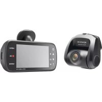
| Model | STZ-RF200WD |
| Dimensions (main unit) | 79 (W) × 104 (D) × 22.5 (H) mm |
| Dimensions (cameras) | 23.5 (Φ) × 34.4 (D) mm |
| Dimensions (GPS) | 27.4 (W) × 33 (D) × 13 (H) mm |
| Dimensions (switch) | 25.8 (W) × 36.9 (D) × 9.5 (H) mm |
| Weight (main unit) | 105 g |
| Weight (cameras) | 42 g (each) |
| Weight (GPS) | 14 g |
| Weight (switch) | 9 g |
| Power supply | 12 V DC, 0.48 A |
| Protection rating (main unit) | IP55 |
| Protection rating (cameras, GPS, switch) | IP66/67 |
| Recording resolution | 1920 × 1080 (Full HD) |
| Frame rate | 27.5 fps |
| Sensor | 2 megapixels (effective 1.86 MP) |
| Viewing angle | 195° diagonal (effective 181°) |
| Storage media | microSDHC/SDXC, Class 10 UHS-I, 16 GB to 256 GB |
| Connectivity | Wi-Fi 802.11ac, mobile app (iOS/Android), PC viewer |
| Recording functions | Continuous, event (G-sensor), manual |
| GPS | GPS/GLONASS |
| Operating temperature | -20°C to +60°C |
| Maintenance | Clean the lens with a soft cloth and water; format the SD card once a month |
| Safety instructions | Use only on 12 V DC battery; do not disassemble; avoid shocks and excessive humidity |
Frequently Asked Questions - STZRF200WD KENWOOD
User questions about STZRF200WD KENWOOD
0 question about this device. Answer the ones you know or ask your own.
Ask a new question about this device
Download the instructions for your Dashboard camera in PDF format for free! Find your manual STZRF200WD - KENWOOD and take your electronic device back in hand. On this page are published all the documents necessary for the use of your device. STZRF200WD by KENWOOD.
USER MANUAL STZRF200WD KENWOOD
- Updated information (the latest Instruction Manual, etc.) is available from https://www.kenwood.com/cs/ce/.
For your records
Record the serial number, found on the back of the unit in the spaces designated on the warranty card, and in the space provided below. Refer to the model and serial numbers whenever you can upon your Kenwood dealer for information or service on the product.
Model STZ-RF200WD
Serial Number

US Residents Only
Register Online
Register your KENWOOD product at www.kenwood.com/usa
Read this manual thoroughly before installation wiring and use. Install and wire the unit correctly in accordance with the Safety Precautions (p.4 - p.7). Please store this manual in a secure location and refer to it as needed.
In the event of an accident or damage to the motorsports vehicle which the unit is installed
Turn the unit off and remove the SD card to prevent important videos and recording files from being overwritten. ( p.11)
Contents
Safety Precautions 4
Precautions for Use 7
FCC/IC. 9
Check the Items Included in the Package .... 10
Name and Function of Each Part 10
Installation 11
Motorsports CAM Functions 15
Using the Cell Phone App. 17
Using the Computer Viewing Program 19
Updating the Firmware 19
Troubleshooting 20
Appendix 22
Important Software Notifications 25
Specifications 26
Safety Precautions
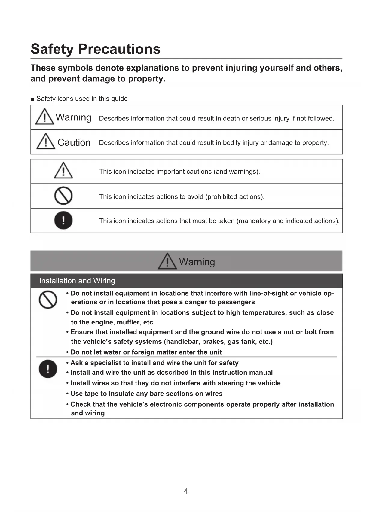
These symbols denote explanations to prevent injuring yourself and others, and prevent damage to property.
Safety icons used in this guide
| Warning | Describes information that could result in death or serious injury if not followed. |
| Caution | Describes information that could result in bodily injury or damage to property. |
| This icon indicates important cautions (and warnings). | |
| This icon indicates actions to avoid (prohibited actions). | |
| This icon indicates actions that must be taken (mandatory and indicated actions). |

Installation and Wiring

- Do not install equipment in locations that interfere with line-of-sight or vehicle operations or in locations that pose a danger to passengers
- Do not install equipment in locations subject to high temperatures, such as close to the engine, muffler, etc.
- Ensure that installed equipment and the ground wire do not use a nut or bolt from the vehicle's safety systems (handlebar, brakes, gas tank, etc.)
- Do not let water or foreign matter enter the unit

- Ask a specialist to install and wire the unit for safety
Install and wire the unit as described in this instruction manual
Install wires so that they do not interfere with steering the vehicle - Use tape to insulate any bare sections on wires
- Check that the vehicle's electronic components operate properly after installation and wiring
| ·Store SD cards, packing materials or unused accessories such as screws in a location away from small children. ·Plug in the power cable correctly ·Hold the in-line connectors when unplugging the power cable ·Disconnect the in-line connector for power cable when not using the Motorsports CAM for extended periods of time ·Make sure to use the included parts and specified components ·Clean the power cable at the battery connection point periodically | |
| Use | |
| ·Do not remove the SD card or disconnect in-line connectors with wet hands. It could result in fire, electric shocks, or malfunction. ·Do not disassemble repair or try to modify the unit. It could result in traffic accidents, fire, electric shock, or malfunction. Modifying the unit or using a modified unit is also a violation of the Radio Act and the Telecommunications Business Act. ·This unit is intended only for vehicles with a DC 12V power supply. Using this unit in any other voltage environment besides 12V DC such as 6V, 24V or other could result in fire and/or damage. ·Do not use if damaged or malfunctioning. If foreign matter enters the unit, or if it produces smoke, abnormal noise, or peculiar odors, stop use immediately and disconnect the power cable. ·Never use the associated cell phone app while driving. Only use it once you have parked in a safe location. ·Can we say use caution when using the switch or the need to glance at the status indicator. Driving safely should be prioritized. ·Do not conduct risky behavior, such as sudden starts or braking, to test whether the unit is working. ·Do not use the unit if there is condensation on it. It could result in malfunctions, heat buildup, or electric shocks. ·Do not subject the unit to strong impacts, like drops, hits, etc. It could result in malfunctions or damage. ·Do not place items with strong magnetic fields near the unit It could result in a malfunction. ·Do not let the unit come into contact with gasoline, liquids, organic solvents, brake fluids, etc. It could result in malfunctions or damage. ·Do not wash the unit or camera when cleaning your vehicle with a pressure washer It could result in a malfunction. | |
| ·Secure disconnected in-line connectors with tape to prevent water or foreign matter from entering It could result in a malfunction. ·Always use fuses of the specified capacity and ask a specialist to replace them. If a fuse above the specified capacity is used, it could result in fire or malfunction. | |
| Handling near electronic medical equipment | |
| If used near electronic medical equipment such as implantable pacemakers or implantable cardioverter-defibrillators, keep the unit at least 22 cm (8.664") from such equipment. The radio waves may negatively affect the operations of medical devices. | |
| Contact for malfunctions | |
| If a malfunction occurs, stop use immediately and contact the office listed in this manual. Continued use may result in unanticipated accidents, fires, or electric shocks. |
| Installation and Wiring | |
| Do not install in locations subject to high-pressure water or locations with high levels of humidity, dust, or soot Water, soot, etc. entering the unit could result in smoke, fire, or malfunction. | |
| Do not place items on top of the unit or that cover the unit. Heat trapped inside the unit could result in fire or malfunction. | |
| Cautions when handling cables Make sure cables have sufficient slack so that they are not subject to excessive force, and install them so that any sections that move do not bend beyond a radius of 40 mm (1.57"). Prevent cables from becoming damaged, pulled excessively, bent, twisted, modified, pressed upon, installed near high-temperature equipment, etc. It could result in fires, electronic shocks, and malfunctions from disconnections or shorts. | |
| Cautions against deteriorated paint on the installation surface Please check the paint on installation surfaces where included double-sided tape will be affixed for deterioration. Deteriorated paint could reduce adhesion power and cause the unit to fall off. The adhesion power of double-sided tape may affect the external appearance of the motorcycle. | |
| Use | |
| Do not use the unit for any non-vehicle use. It could result in smoke, fire, or electric shock. | |
| Check the installation before driving A loose unit or connected component of the unit could fall or interfere with driving cause an injury, traffic accident or malfunction of this unit. | |
| If you notice malfunctions in the unit If you notice that the unit is malfunctioning in any way, refer to the Troubleshooting section (→p.20) to see if a solution is listed there. If you cannot find a solution, disconnect the power cable and restart the unit. If operations do not return to normal after restarting, contact the office listed in this manual. | |
| The unit is equipped with a GPS device. Recorded drive data includes location information. |
Installation
- Only install the unit with the key removed from the vehicle's ignition so that the engine does not start unexpectedly.
- Install the unit in a location that will not interfere with vehicle operations.
Event recording may not work properly if a mistake is made during installation. Refer to the instruction manual for directions, the angle of installation, etc. to install the unit properly. ( p.12) - Before using included double-sided tape to install the unit, remove dirt and fingerprints from the installation location using a commercial cleaning cloth and wait for the location to dry before proceeding. Reusing tape, using general purpose double-sided tape, etc. for the installation will result in weaker adhesion power and presents a risk of the unit falling off. Use cables as needed to secure the camera in place.
- Wrap cables using cable ties or commercial soft edge masking tape so that they do not interfere with driving.
- Do not install in locations that will be subject to high temperatures (near the engine, muffler, etc.) or high pressures (when the suspension bottoms out while someone is on the bike).
- Disconnect the in-line connectors on the power cable when not using the unit for extended periods of time. It could drain the battery. Secure disconnected in-line connectors with tape to prevent water or foreign matter from entering.
Use
- Do not block or dirty the camera lens or place reflective material near the lens.
-
LED signs may flicker or blink in recordings. There is no guarantee that traffic lights will be identifiable and recorded.
-
Our company bears no responsibility for the accuracy, completeness, or suitability of recorded content.
- Please regularly check that the unit is recording normally, including confirming that no malfunctions have occurred in the unit or SD card.
- Always check that the indicator is not producing any abnormal displays when the unit is powered on.
- Always check the installation prior to use.
Copyrights
- In some instances, video, images, and audio content may not be recorded without permission from the copyright holder, even if used for personal enjoyment.
- Even if permission is obtained from the copyright holder for video, images, and audio content, in some instances, use may not be allowed for viewing outside of personal enjoyment.
Caring for the unit
- Wipe the unit gently with a dry silicone or soft cloth if it becomes dirty. If the unit is very dirty, wipe away the dirt with a cloth moistened with a neutral cleaner, then wipe off the cleaner. Wiping the unit with a hard cloth or volatile substance such as paint thinner or alcohol could result in scratches, deformations, deterioration, or malfunction.
- Images may not record clearly if the lens is dirty. Check the lens for dirt before driving. If the lens is dirty, gently wipe away the dirt using a soft cloth moistened with water. Wiping forcefully with a dry cloth may scratch the lens.
Recommended SD cards
| Type | microSDHC microSDXC |
| Capacity 16 GB to | 256 GB |
| Speed class Class | 10 UHS-I |
| File system FAT32 | |
| Allocation size 64 KB | |
- We cannot guarantee the operations of every SD card.
- We recommend using a high-durability SD that is suited for repeated recording (dashcam).
- When using an SD card in the unit for the first time, the Status LED may show an error warning. An SD Card may need to be re-formatted by the App or computer for normal operation.
Precautions when using SD cards
- When using a commercially available SD card, read the instruction manual included with the card.
- Always have the unit powered off when inserting or removing an SD card. If the unit is powered on, there is a risk of damage to data or the SD card.
- Always format new SD cards in the unit before using them.
- Always check whether video is recording properly after inserting an SD card.
-
Make sure to push or pull SD cards in the proper direction and do not bend, force, or hit them. Do not touch terminal pins directly with your hands or let them get into contact with metal objects. There is a risk of data being damaged or lost due to electric shock.
-
Always make sure to back up (copy) important files saved on SD cards to a computer or other unit as soon as possible. Data may be lost depending on how SD cards are used.
Please be aware that our company is in no way responsible for compensating any damages caused from the loss of stored data.
- Formatting SD cards or deleting data using the unit or formatting SD cards on a computer only changes the file management information and does not completely erase all data stored in SD cards. When an SD card will no longer be used, we recommend using commercially available data deletion software for computers to completely erase all data in the SD card. Data inside SD cards is managed at the responsibility of the customer.
- SD cards are consumable products. We recommend periodically replacing them with new ones depending on how they are used.
- You may not be able to overwrite or delete data on SD cards, even when used normally.
- As a rule, format your SD cards once a month.
- Do not place objects on top of SD cards, drop them, or use force on them. Store them in a clean, dry place with low humidity.
- The warranty does not cover equipment malfunctions caused by SD cards.
FCC WARNING
This equipment may generate or use radio frequency energy. Changes or modifications to this equipment may cause harmful interference unless the modifications are expressly approved in the instruction manual. The user could lose the authority to operate this equipment if an unauthorized change or modification is made.
FCC NOTE
- This equipment has been tested and found to comply with the limits for a Class B digital device, pursuant to Part 15 of the FCC Rules. These limits are designed to provide reasonable protection against harmful interference in a residential installation.
-
This equipment may cause harmful interference to radio communications, if it is not installed and used in accordance with the instructions. However, there is no guarantee that interference will not occur in a particular installation. If this equipment does cause harmful interference to radio or television reception, which can be determined by turning the equipment off and on, the user is encouraged to try to correct the interference by one or more of the following measures:
-
Reorient or relocate the receiving antenna.
- Increase the separation between the equipment and receiver.
- Connect the equipment into an outlet on a circuit different from that to which the receiver is connected.
- Consult the dealer or a professional installation technician for help.
This transmitter must not be co-located or operated in conjunction with any other antenna or transmitter.
CANICES-3(B)/NMB-3(B)
IC (Industry Canada) Notice
This device contains license-exempt transmitter(s)/receiver(s) that comply with Innovation, Science and Economic Development Canada's license-exempt RSS(s). Operation is subject to the following two conditions:
- This device may not cause interference.
- This device must accept any interference, including interference that may cause undesired operation of the device.
CAUTION
This equipment complies with FCC/IC radiation exposure limits set forth for an uncontrolled environment and meets the FCC radio frequency (RF) Exposure Guidelines and RSS-102 of the IC radio frequency (RF) Exposure rules. This equipment has very low levels of RF energy that is deemed to comply without maximum permissive exposure evaluation (MPE). But it is desirable that it should be installed and operated keeping the radiator at least 20~cm ( 7.874'' ) or more away from a person's body.
Supplier's Declaration of Conformity
Trade Name: KENWOOD
Product: Dashboard Camera
Model Name: STZ-RF200WD
Responsible Party:
JVCKENWOOD USA CORPORATION
2201 East Dominguez Street,
Long Beach, CA 90810, U.S.A.
PHONE: 310 639-9000
THIS DEVICE COMPLIES WITH PART 15 OF THE FCC RULES. OPERATION IS SUBJECT TO THE FOLLOWING TWO CONDITIONS:
- THIS DEVICE MAY NOT CAUSE HARMFUL INTERFERENCE, AND
- THIS DEVICE MUST ACCEPT ANY INTERFERENCE RECEIVED, INCLUDING INTERFERENCE THAT MAY CAUSE UNDESIRED OPERATION.
Complies with IMDA Standards DB02771
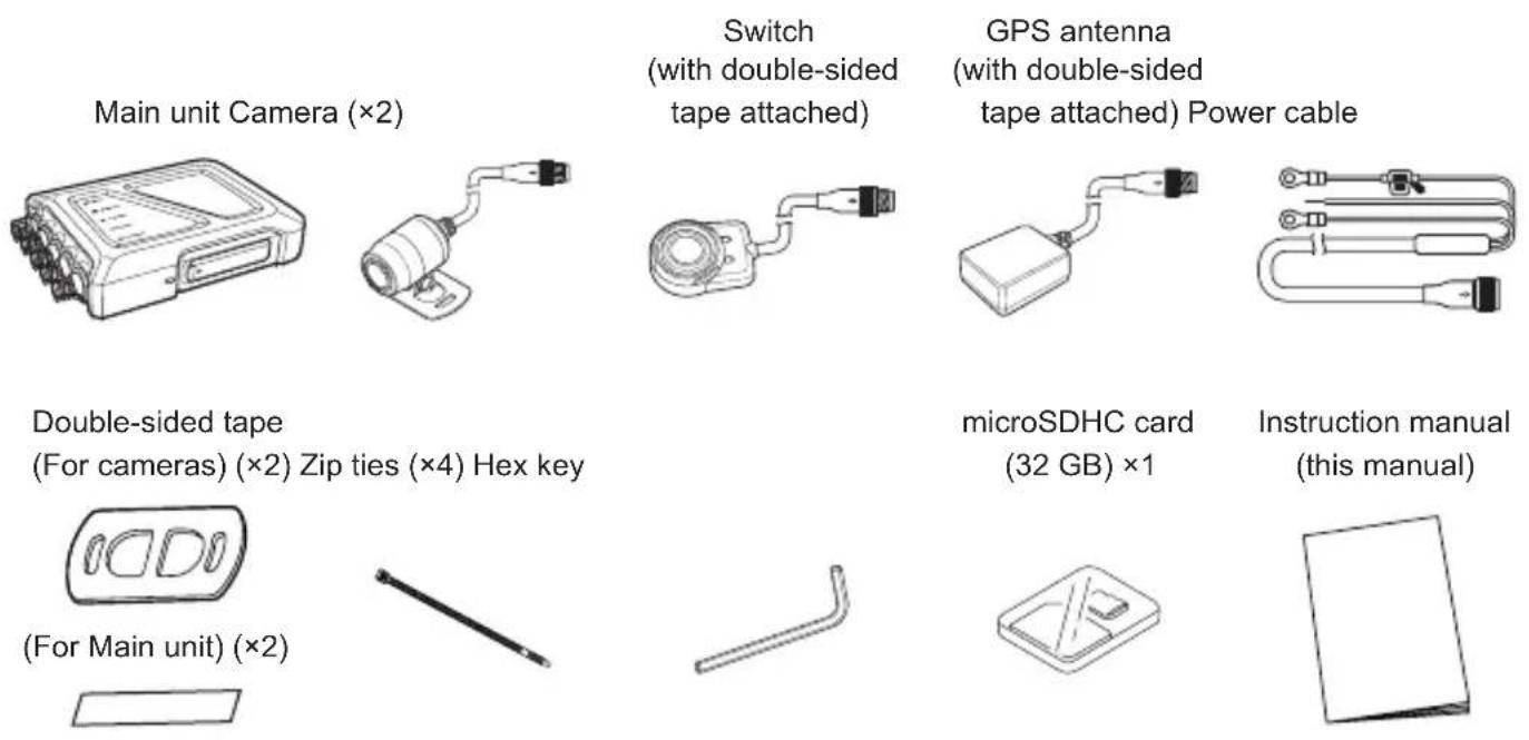
Check the Items Included in the Package
Check that all items are included before installing the unit.
Name and Function of Each Part
Inserting and removing the SD card
Inserting an SD card
- Open the side door to access the SD card slot.
- Press the SD card into the SD card slot until you hear a click, then close the side door.
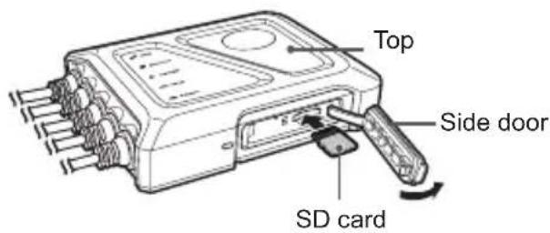
Insert the SD card with the pins facing the top of the unit.
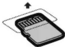

- Always turn the unit off before inserting or removing an SD card.
-
We strongly recommend using the unit to format SD cards before using them. See the KENWOOD Motorsports CAM Operations Guide when formatting an SD card.
-
You can read the KENWOOD Motorsports CAM Operations Guide on our company website. https://www.kenwood.com/cs/ce
Removing an SD card
- Open the side door to access the SD card slot.
- The SD card will pop out a little when pressed gently. Close the side door after removing the SD card.

- Close the side door properly so that it latches fully and there are no gaps. Otherwise, water or foreign matter could enter and cause a malfunction.
Installation layout
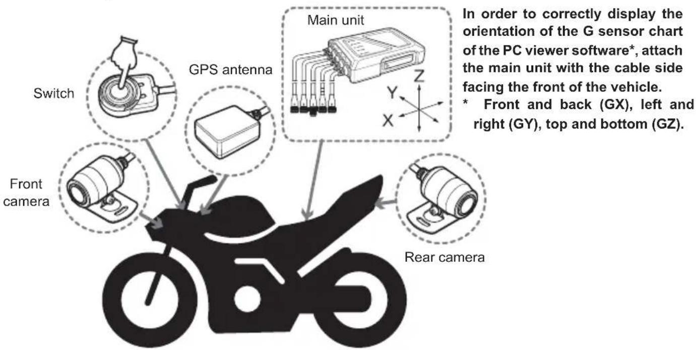

- This installation layout is for reference. Actual installations will vary by motorcycle model.
- Main unit
Install the main unit underneath the seat.
When fastening the main unit to the vehicle, check that there is adequate room to open the SD card slot side door.
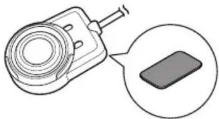
The included double-sided tape must be used when fastening the main unit to the vehicle.
- The included double-sided tape must be affixed to the bottom (the flat surface) of the main unit as shown in the image on the right.
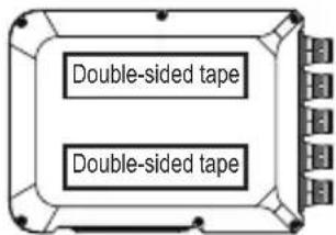

- Before installing the unit with the included double-sided tape, select a flat location on the vehicle, wipe away any dirt or grease on the installation location with a commercially available cleaning cloth, and install the unit after the location has dried. Reusing tape or using general purpose double-sided tape for installation will provide less adhesive power and presents a risk of the unit falling off.
- Do not install in locations that will be subject to high temperatures (near the engine, muffler, etc.) or high pressures (when the suspension bottoms out while someone is on the bike).
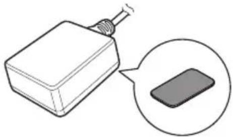
GPS antenna
Install the GPS device in a location where it can easily receive satellite signals, such as near the handlebars or on top of the gas tank. Remove the release paper from the double-sided tape before installing.
- Switch
Install the switch in a location that is easy to operate and will not interfere with safe operation of the motorcycle, such as on or nearby the left handlebar.
Remove the release paper from the double-sided tape before installing.
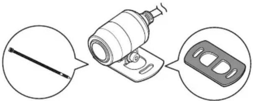
- Front and rear cameras
Install the cameras in locations where the field of view will not be affected by the motorsports vehicle itself.
Remove the protective film from the double-sided tape before installing. Use screws, nuts (not included), and cable ties as needed to secure the cameras in place.
After installation, use the KENWOOD Motorsports CAM App to check the video feed and adjust the camera. See p.18 "Adjusting the field of view" for more details.

- When using double-sided tape to install the unit, remove dirt and fingerprints from the installation location using a commercial cleaning cloth and wait for the location to dry before proceeding. Reusing tape or using general purpose double-sided tape for installation will provide less adhesive power and presents a risk of the unit falling off.
- Use cable ties to secure cables so that they do not droop. Improper wiring or securing could result in wires falling, malfunctions, fires, or accidents.
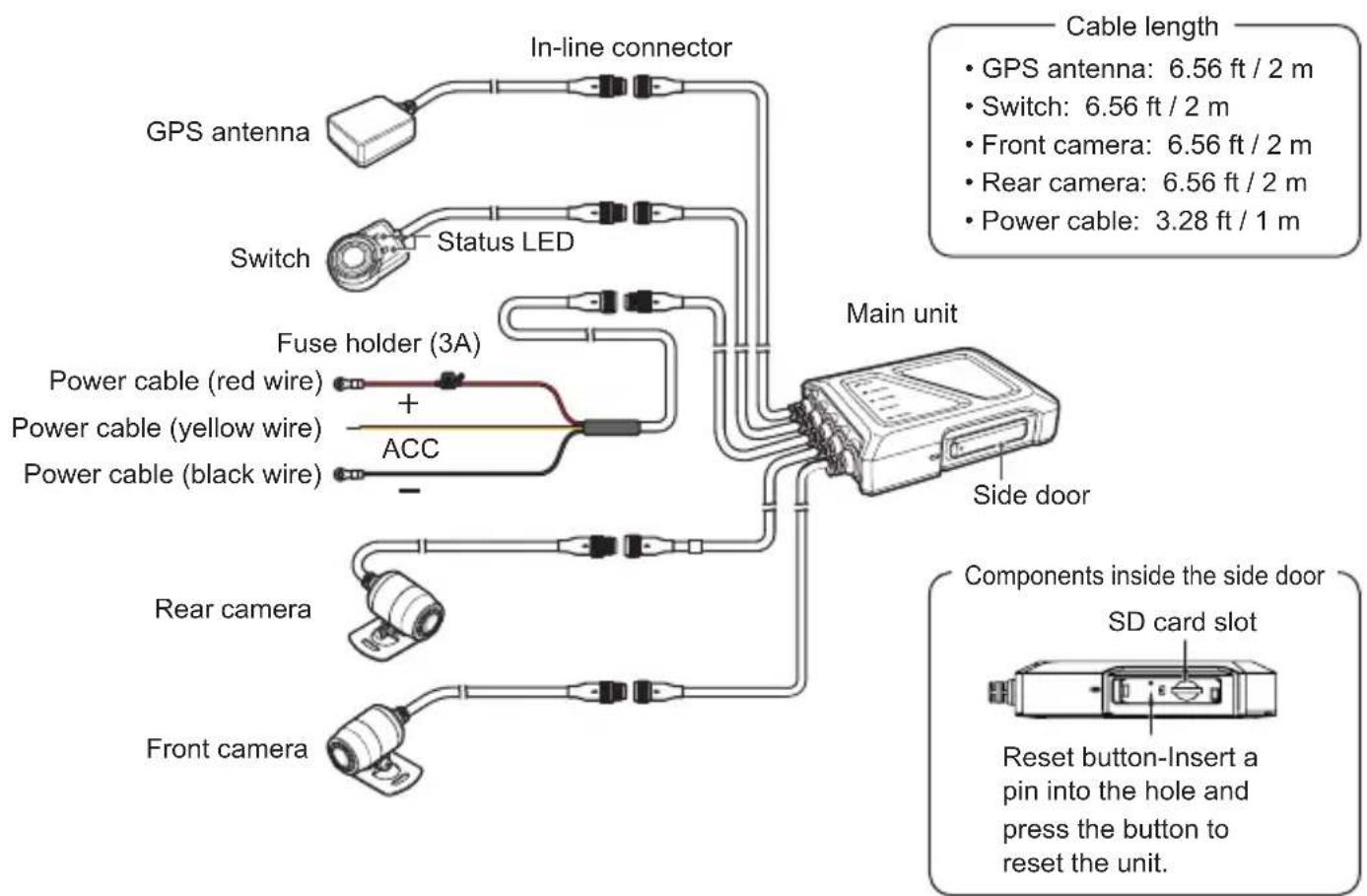
Power cable
Each wire in the power cable assembly connects to the bike battery.
Unscrew the battery's negative/ground terminal. Then unscrew the positive terminal.
Place the round terminal on the power cable (red wire) on the battery's positive terminal, then tighten with the original terminal screw.
Next, place the round terminal on the power cable (black wire) on the battery's negative terminal, then tighten with the original terminal screw.
When connecting the power cable's yellow wire, make sure that it is connected properly to the ACC power supply.

- When unscrewing battery terminals, remove the negative one first, check that no cables are contacting the terminal, and then remove the positive terminal. Connecting starts with the positive terminal.
- Remove the key from the ignition to prevent short circuiting the unit.
- Consult a professional installation technician if wire connections are causing problems. Incorrect installation or wiring may severely damage the motorcycle or cause an accident.
- Install the fuse holder in a location where it will not come into contact with water.
- Connecting cables
Connecting cables
- Check the pin layout of the in-line connectors and align the pins when connecting them.
- Tighten the locking nut to secure the connection.
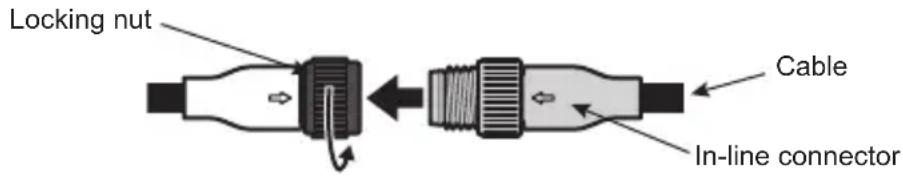
Disconnecting cables
- Loosen the locking nut.
- Hold the cable by the in-line connector and disconnect it.


- Holding the cable when disconnecting could damage the cable. Always hold the in-line connectors to release a connection.
- Be careful to not mix up the cables for the front and rear cameras. Cables for the rear camera have a white marker tube.
Securing cables
Secure each cable to the motorcycle using cable ties or electrical tape.
Make sure they do not interfere with the rider's ability to control the bike.

- Check that the handlebar can rock back and forth and that the wires do not interfere with operations when the suspension bottoms out.
Powering the unit
When the bike's ignition is set to ACC or ON and the unit is switched on, the unit will start continuous recording after completing a system check. When the ignition is turned to OFF, the unit will automatically power off.
- The LED lights may illuminate for approximately 30 seconds while powering down which is normal.
Motorsports CAM Functions
The unit records videos and saves them to the microSD card. Always insert an SD card into the SD card slot before using the unit. See p.11 for details.
Function settings
You can change the function settings for the unit using the KENWOOD Motorsports CAM App. See the KENWOOD Motorsports CAM App Guide for details.
Recording functions
Continuous recording
The unit will start continuous recording when it powers on. The default setting is for each recorded minute to be saved as a separate video file. The recording time can be changed with the KENWOOD Motorsports CAM App.
Event recording
Event recording will start if a sudden force is detected during continuous recording. The unit will record from 10 seconds before a large force affects the bike until 5 seconds after. The unit will return to continuous recording after event recording has finished.
Manual recording
Manual recording will start if the switch button is pressed during continuous recording.
Saving and overwriting recorded files
Recorded files are saved separately as continuous recordings, event recordings, and manual recordings. If the save region on the SD card becomes full, files on the SD card will be overwritten beginning with the oldest file. See "Recording time" and "Possible number of files" ( p.24) for details.
Audio settings
Audio recording can be set to ON or OFF.
You can change the setting with the KENWOOD Motorsports CAM App.
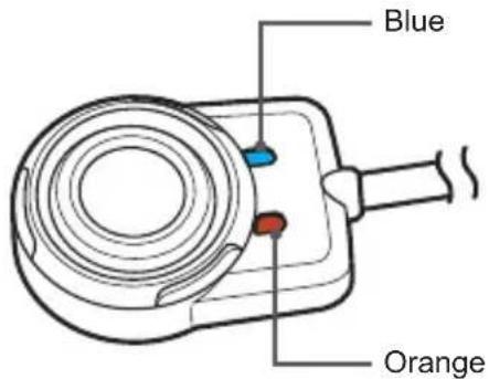
| State LED display pattern | |||
| System check at start-up (from startup to the start of recording) | Blue Orange | Blue lit and orange blinks once per second | |
| ·Continuous recording (unsynchronized time) ·Continuous recording (synchronized time) | Blue Orange | Blue lit, orange unlit | |
| ·Wireless LAN (waiting for connection) ·Wireless LAN (connected) | Blue Orange | Orange lit, blue blinks once per second | |
| ·Event recording ·Manual recording | Blue Orange | Blue and orange lit | |
| Error (press the switch to display error details) | Blue Orange | Orange lit, blue unlit | |
| Error details | Updating firmware | Blue Orange | Orange lit, blue unlit |
| SD card error* (displayed for 5 seconds) | Blue Orange | Blinks for 0.5 seconds over 5 seconds | |
| Front camera error* (displayed for 5 seconds) | Blue Orange | Blue blinks for 0.5 seconds and orange is lit over 5 seconds | |
| Rear camera error* (displayed for 5 seconds) | Blue Orange | Blue is lit and orange blinks for 0.5 seconds over 5 seconds | |
| GPS error* (displayed for 5 seconds) | Blue Orange | Blue is lit, orange will blink twice every 0.5 second with a 0.2 second interval between each blink for 5 seconds | |
| High temperature error* (displayed for 5 seconds) | Blue Orange | Blue will blink twice every 0.5 second with a 0.2 second interval between each blink and orange is lit for 5 seconds | |
| Wired switch error* (displayed for 5 seconds) | Blue Orange | Blue and orange will both blink twice every 0.5 second with a 0.2 second interval between each blink for 5 seconds | |
Using the Cell Phone App
You can use the KENWOOD Motorsports CAM App to view and download videos recorded and saved to the SD card. You can also change the unit settings.
Installing the KENWOOD Motorsports CAM App
Minimum system requirements (cell phone)
Android 7.0 or later
iOS 11 or later
Search for the KENWOOD Motorsports CAM App on the Google Play Store or the App Store.
Then download and install the app on your cell phone.

- Check that your cell phone is connected to the internet (either via mobile data or WiFi).
Connect your cell phone to the unit using a wireless LAN connection
- Press and hold the switch button on the unit for 3 seconds to switch to wireless LAN mode.
The orange status LED will light up and the blue one will blink. This shows that the unit is preparing to connect to your cell phone.
- Open the settings on your cell phone.
- Set WiFi to ON.
Bring up the list of available networks.
- Tap STZ_RF200WD_(serial number).
- Enter the password, tap connect, and it will connect with the unit.

- The default password is "12341234".
- You will only need to input the password the first time. Subsequent connections will be automatic.
Check the KENWOOD Motorsports CAM Operating Guide on our company website for more detailed operating instructions.
https://www.kenwood.com/cs/ce
Adjusting the field of view
- Open the KENWOOD Motorsports CAM and tap "Image angle adjustment" on the main menu. It will start with the live feed from the front camera.
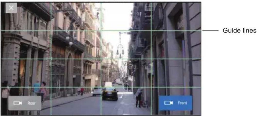

- Tap "Rear" to switch to the live feed from the rear camera.
- Tap "X" when you are finished with the screen.
-
If it starts with the live feed from the rear camera, the front and rear camera connections are incorrect. Check the camera cable connections.
-
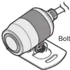
Use the included hex key to loosen the bolt on the installation bracket.
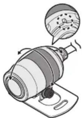
- Rotate the camera while checking the live feed and adjust the camera to your preferred field of view. Make sure that the indentation on the back of the camera is facing up.
- Once the adjustment is complete, tighten the bolt and lock the camera in place.
Using the Computer Viewing Program
The KENWOOD Motorsports CAM Viewer is a computer program designed for viewing video recorded by the unit.
The program can be downloaded from our company website.
Check the product page for details.
Installing the software
Double-click the program installer downloaded to your computer and follow the directions on your screen to install the program.
Operating environment
Windows
| Compatible OS | Windows 10 (32-bit/64-bit) |
| CPU Intel Core i3 2GHz or better | |
| Memory 2 GB or more | |
| Display 1280 × 800 or greater | |
| Sound | Functions that can playback PCM sound in Windows |
Mac OS X
| Compatible OS | MAC OS 10.14 or later |
Check the KENWOOD Motorsports CAM Viewer Operating Guide on our company website for more detailed operating instructions.
https://www.kenwood.com/cs/ce
Updating the Firmware
The unit's firmware may need updating to improve performance and fix bugs.
We recommend always using the latest firmware version.
- Download the latest version from our company website and copy it to an SD card.
- Unzip any files downloaded as zip files before copying them to an SD card.
- Insert the SD card with the copy of the firmware into the Motorsports CAM and power the unit on.
- The Motorsports CAM will check the SD card when it starts up.
It will update itself if it finds a new version of the firmware.
The orange status LED will light up when the update starts.
- The unit will automatically restart once the update is complete and the blue LED will light up.
- Check the firmware version.
Connect to the unit with your cell phone, go to "Settings" "Firmware" from the KENWOOD Motorsports CAM main menu, and check that the latest version is installed.

- Never power the unit off or remove the SD card during a firmware update.
Troubleshooting
| Issue Cause / Solution | |
| The indicator does not light up even though the vehicle ACC is ON. | Is the fuse blown?Address the cause of the blown fuse and replace the fuse.(Always use fuses of the specified capacity) |
| Is the in-line connector for the power cable or switch cable disconnected?Check the connections of the in-line connectors. | |
| The orange status LED is blinking.(see p.16) | Press the switch and the status LEDs will inform you of the error details. |
| The display indicates an SD card error.(see p.16) | Is the SD card inserted correctly?If there is no change after the SD card is inserted correctly, format the SD card or replace it with a new one. |
| The display indicates a front camera error.(see p.16) | Is the in-line connector for the front camera disconnected?Check the connections of the in-line connectors.(see p.14) |
| The display indicates a rear camera error.(see p.16) | Is the in-line connector for the rear camera disconnected?Check the connections of the in-line connectors.(see p.14) |
| The display indicates that the camera is not connected while adjusting the recording angle.(see p.16) | Is the in-line connector for the camera cable disconnected?Check the connections of the in-line connectors.(see p.14) |
| The display indicates a GPS error.(see p.16) | Is the in-line connector for the GPS device disconnected?Check the connections of the in-line connectors.(see p.14) |
| The display indicates that the temperature is high.(see p.16) | The unit is hot. Turn off image stabilization and temporarily reduce the frame rate to prevent heat from generating and continue recording. Stop recording if the temperature does not drop. |
| The display indicates a switch error.(see p.16) | Is the in-line connector for the switch disconnected?Check the connections of the in-line connectors.(see p.14) |
| The camera and main unit will generate heat during use. | Is it too hot to touch?It will heat up during use. Stop use immediately if it is too hot to touch and contact the office listed in this manual. |
| The time displayed on recorded video is incorrect. | Is the top of the GPS antenna covered by metal or something with a metal coating?Remove the item covering it. Or move the GPS antenna to a location where nothing will cover it. If the issue is not resolved, use a dedicated cell phone app to synchronize the time. |
| Recorded video isn't clear. | Is video quality set to FINE? ✓ Change the video quality setting to FINE. |
| Is the camera lens dirty? ✓ Wipe the lens with a lens cleaner or soft cloth dampened with water. | |
| Video from the front and rear camera are swapped. | Are the camera cables connected to the correct connection points on the main unit? ✓ Disconnect the in-line connectors and connect them to the correct connection points. |
| The G-sensor does not match vehicle movement (up/down, forward/backward, left/right) | Is the unit oriented (X, Y, Z) to the vehicle's longitudinal, lateral, and vertical axes? ✓ Align the main unit and vehicle axes as best as you can. * This will not affect impact notification sensitivity. |
| Event recording does not work. | Is impact notification sensitivity turned off or set low? ✓ Gradually increase the impact notification sensitivity setting and check again. |
| Event recording starts frequently. | Is the unit fixed securely to the vehicle? ✓ Secure the unit so that it does not move. |
| Is impact notification sensitivity set high? ✓ Gradually decrease the impact notification sensitivity setting and check again. | |
| GPS location data is not being received. Or the location is incorrect. | Is the top of the GPS antenna covered by metal or something with a metal coating? ✓ Remove the item covering it. Or move the GPS antenna to a location where nothing will cover it. |
| Were you driving through a tunnel, a ravine, among high-rise buildings, through an underpass, or something similar? ✓ The surrounding environment may make it hard to receive GPS signals in some places. Change locations and check whether location information is received correctly. | |
| My cell phone won't connect to the unit over a wireless LAN connection. | Did you switch the unit to wireless LAN mode? ✓ Press and hold the switch for 3 seconds to switch to wireless LAN mode. (See p. 16 for details) ✓ Was the password entered correctly? ✓ Enter the correct password. ✓ Reset the wireless LAN password using the Motorsports CAM App and enter the default password, "12341234". |
| The wireless LAN connection is good, but the app can't connect with the main unit. | Is the main unit already connected to another cell phone? ✓ It cannot connect to multiple cell phones at the same time. Disconnect the other cell phone. |
| Video from the rear camera is not recording. | Is the rear camera set to OFF? ✓ Set the rear camera to ON. |
Wireless Link Specifications
| Standard IEEE802.11ac (Default Settings) IEEE802.11n (Optional Settings) | ||
| Security WPA2 WPA2 | ||
| Frequency Range 5735-5835 MHz 2400-2473 MHz | ||
| Transfer Rate 433 Mbps (802.11ac) 150 Mbps (802.11n) | ||
| Output Power 12 dBm ±2 dB (802.11ac) 12 dBm ±2 dB (802.11n) | ||
On Wireless Link Security
Since the Wireless Link communicates over radio waves, there is the benefit that you are able to access the Link freely as far as the radio waves reach. On the other hand, without proper security settings there may be a risk of hacking or abusive invasion by malignant third parties. We recommend that you use Wireless Link after setting up proper security of the devices connected.
Please note that we are not liable for any damage or troubles pertaining to security when using this function.
Radio Interference with Bluetooth Devices
With the Wireless Link in use, if Bluetooth devices are in operation nearby, there may be radio interference causing reduced transmission speeds or disconnections. In this case, please do not use the devices simultaneously.
Receiving positioning satellite (GPS, GLONASS) information
- Positioning will begin when the unit powers on. Positioning may take 5 minutes to complete depending on the positioning status of satellites.
- Satellite signals cannot pass through solid matter (except for glass). Positioning will not work inside tunnels or buildings. Bad weather and dense overhead objects (e.g., trees, tunnels, viaducts, skyscrapers, etc.) may affect signal reception.
Speed, location, and other information will not display properly if satellite signals cannot be properly received.
- Positioning data are reference values.
Important trademarks and software notifications
- microSDXC and microSDHC are trademarks of SD-3C, LLC.
- OpenStreetMap is a registered trademark of the OpenStreetMap Foundation.
Windows is a registered trademark of Microsoft Corporation in the USA and other countries.
Mac and OS X are trademarks of Apple, Inc. registered in the USA and other countries. - Intel Core is a trademark or registered trademark of Intel Corp.
- WiFi is a registered trademark of Wi-Fi Alliance.
- QR code is a registered trademark of Denso Wave, Inc.
This product is licensed under the AVC Patent Portfolio License for the following purposes only.
1) When customers record videos for personal and non-commercial purposes that comply with the MPEG-4 standard (hereafter, AVC Video).
2) When playing back AVC Video (recorded by customers themselves for non-commercial purposes or recorded by a provider licensed through MPEG LA)
See the MPEG, LLC website for details.
http://www.mpegla.com
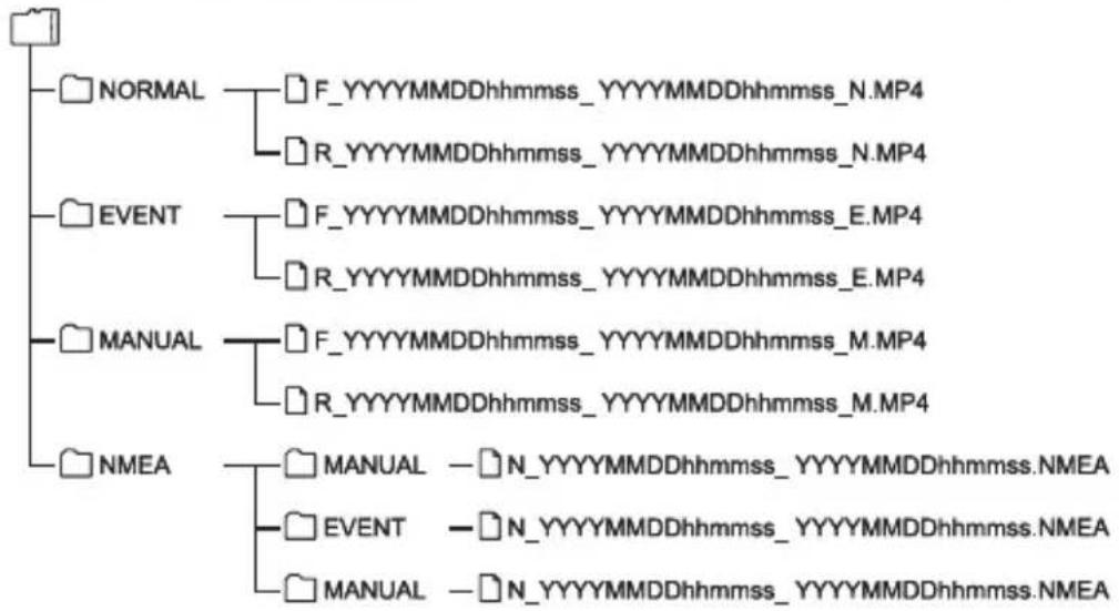
File and folder organization
Files saved on SD cards are saved in individual folders.
File names are automatically created based on the date and time of the video or recording.

- Do not use computers, etc. to change or delete files on SD cards. Files may not play correctly in the unit or the computer program.
Recording time
| Video quality | SD card capacity | ||||
| 16 GB 32 GB 64 GB 128 GB 256 GB | |||||
| Fine 93 minutes | utes | 190 minutes | 384 minutes | 772 minutes | 1,547 minutes |
| Normal | 170 minutes | 348 minutes | 703 minutes | 1,414 minutes | |
- The above recording times are the total (maximum) time of continuous recording.
- Recording times are approximate. Recording times may be less depending on the image being recorded.
Possible number of files
| Recording type | SD card capacity | ||||
| 16 GB 32 GB 64 GB 128 GB 256 GB | |||||
| Event recording | 10 20 40 80 160 | ||||
| Manual recording | 10 20 40 80 160 | ||||
- The number of continuous recording files may change depending on the number of event videos and manual videos recorded.
The software license for this product
The software included in this product consists of multiple software components, each of which is copyrighted by JVCKENWOOD or a third party. This product uses software components (hereafter, "Licensed Software") based on software license agreements specified by JVCKENWOOD and third parties.
Some of the Licensed Software is free software and is used under a GNU General Public License or Lesser General Public License (hereafter "GPL/ LGPL"). As a result, the source code of those software components must be made available when distributing them in an executable format. Please visit the following website for information on distributing this source code.
Website
https://www.kenwood.com/gpl/
Please be aware that we cannot answer questions regarding the source code.
Please be aware that source code will not be provided for Licensed Software not covered by GPL/ LGPL.
Software components distributed under GPL/ LGPL are licensed to customers free of charge and such software components are provided with no warranty, express or implied, within the scope of applicable laws.
Except for as determined by applicable laws or provided via written agreement, the copyright holder and any person who changes or redistributes the software components are in no way liable for any damage caused through use or not being able to use said software components.
See each GPL/LGPL for details on terms of use and matters that must be observed for the software component.
Read the applicable licenses for software components covered by GPL/LGPL included in this equipment carefully when using the unit.
Each license is regulated by a third party other than JVCKENWOOD, and the original text (English) can be viewed using the cell phone app for this product.
KENWOOD Motorsports CAM licensee information
- Open KENWOOD Motorsports CAM
- Press the "Menu" button on the main menu
- Select "Guide" "License information"
Motorsports CAM license information
- Open KENWOOD Motorsports CAM
- Press the "Settings" button on the main menu
- Select "Drive recorder license information"
Specifications
| Water-proofing, Dustproofing | Main unit | IP55 |
| Cameras | IP66/67 | |
| GPS IP66 | 67 | |
| Switch IP66 | 66/67 | |
| Front and rear camera units | Image sensors | 2 megapixels (effective pixels: 1.86 megapixels) |
| Lens viewing angle | 195° diagonal (effective angle: 181°) | |
| Frame rate | 27.5 fps | |
| F-number | 2.2 | |
| Recording resolution | 1920 × 1080 | |
| Video quality | FINE / NORMAL | |
| Video file format | MP4 (video format: H.264 audio format: AAC) | |
| Recorded file length | 30 seconds / 1 minute / 3 minutes (recording time for one file) | |
| Recording modes | Continuous recording, event recording, manual recording | |
| Data recorded | Video file, time and date, speed, location information | |
| Audio recording | ON / OFF | |
| HDR Yes | ||
| G-sensor | Yes (5 impact sensitivity settings / OFF) | |
| GPS Yes | ||
| Electric image stabilization | Yes | |
| Positioning satellites | GPS / GLONASS | |
| Storage media | microSDHC, microSDXC Class 10 UHS-I | |
| 16 GB to 256 GB | ||
| Recorded video playback methods | KENWOOD Motorsports CAM App | |
| -iOS 11 or later | ||
| -Android 7 or later | ||
| KENWOOD Motorsports CAM Viewer | ||
| -Microsoft Windows 10 | ||
| -Apple Mac OS 10.14 (Mojave) or later | ||
| Power supply DC 12V | ||
| Power consumption | 0.48 A | |
| Measurements | Main unit | 79 (W) × 104 (D) × 22.5 (H) mm3.110 (W) × 4.094 (D) × 0.886 (H) inches |
| Cameras | 23.5 (Φ) × 34.4 (D) mm0.925 (Φ) × 1.354 (D) inches | |
| GPS | 27.4 (W) × 33 (D) × 13 (H) mm1.097 (W) × 1.299 (D) × 0.514 (H) inches | |
| Switch | 25.8 (W) × 36.9 (D) × 9.5 (H) mm1.016 (W) × 1.453 (D) × 0.374 (H) inches | |
| Weight | Main unit | 105 g (0.2315 lb)* |
| Cameras | 42 g (0.0926 lb)* | |
| GPS 14 g | (0.0309 lb)* | |
| Switch 9 g | (0.0918 lb)* | |
| Operating temperature | -20 °C to +60 °C(-4 °F to 140 °F) | |
- Excluding cable.
STZ-RF200WD MANUEL D'INSTRUCTIONS
Partie responsible :
JVCKENWOOD USA CORPORATION
2201 East Dominguez Street,
Long Beach, CA 90810, U.S.A.
TELEPHONE:310639-9000
Conforme aux normes IMDA DB02771
CET APPAREIL EST CONFORME À LA PARTIE 15 DES RÉGLES DE LA FCC. LE FONCTIONNEMENT EST SOUMIS AUX DEUX CONDITIONS SUIVANTES :
- CET APPAREIL PEUT NE PAS PROVOUER D'INTERFÉRENCES DANGEREUSES, ET
- CET APPAREIL DOIT ACCEPTER Toute INTERFERENCE REÇUE, Y COMPRIS LES INTERFÉRENCES SUSCEPTIBLES DE PROVOQUER UN FONCTIONNEMENT INDÉSIRABLE.
https://www.kenwood.com/gpl/
2201 East Dominguez Street,
https://www.kenwood.com/gpl/
- For your records
- US Residents Only
- Register Online
- Contents
- Safety Precautions
- Installation and Wiring
- Installation
- Use
- Copyrights
- Caring for the unit
- Precautions when using SD cards
- FCC WARNING
- FCC NOTE
- CANICES-3(B)/NMB-3(B)
- IC (Industry Canada) Notice
- CAUTION
- Supplier's Declaration of Conformity
- Check the Items Included in the Package
- Name and Function of Each Part
- Inserting and removing the SD card
- Inserting an SD card
- Removing an SD card
- Installation layout
- - Main unit
- Power cable
- - Connecting cables
- Connecting cables
- Disconnecting cables
- Securing cables
- Powering the unit
- Motorsports CAM Functions
- Function settings
- Recording functions
- Continuous recording
- Event recording
- Manual recording
- Saving and overwriting recorded files
- Audio settings
- Using the Cell Phone App
- Installing the KENWOOD Motorsports CAM App
- Connect your cell phone to the unit using a wireless LAN connection
- Adjusting the field of view
- Using the Computer Viewing Program
- Installing the software
- Operating environment
- Updating the Firmware
- Troubleshooting
- Wireless Link Specifications
- On Wireless Link Security
- Radio Interference with Bluetooth Devices
- Receiving positioning satellite (GPS, GLONASS) information
- Important trademarks and software notifications
- File and folder organization
- The software license for this product
- Website
- Specifications
- STZ-RF200WD MANUEL D'INSTRUCTIONS
Brand : KENWOOD
Model : STZRF200WD
Category : Dashboard camera