VT S6 - Fan STEBA - Free user manual and instructions
Find the device manual for free VT S6 STEBA in PDF.
| Brand | Steba |
| Model | VT S6 |
| Appliance Type | Pedestal Fan |
| Power Supply | 220-240 V ~ 50 Hz |
| Power Consumption | 47 W |
| Maximum Airflow | 66,83 m³/min |
| Service Value | 1,42 (m³/min)/W |
| Sound Power Level | 65,75 dB(A) |
| Maximum Air Speed | 3,6 m/s |
| Number of Speeds | 3 (off, low, medium, high) |
| Oscillation Function | Yes, activation by pull cord |
| Height Adjustment | Yes, via adjustment screw |
| Tilt | Yes, up and down |
| Dimensions (approx.) | Adjustable height from 110 to 140 cm, grille diameter 40 cm |
| Weight (approx.) | 5,5 kg |
| Cable Length | 1,5 m (estimate) |
| Grille Material | Painted metal |
| Rotor Blades | 4 plastic blades |
| Child Safety | Protective grille, do not insert objects |
| Cleaning | Unplug, clean with damp cloth, vacuum grille |
| Intended Use | Domestic and similar (offices, hotels, etc.) |
Frequently Asked Questions - VT S6 STEBA
User questions about VT S6 STEBA
0 question about this device. Answer the ones you know or ask your own.
Ask a new question about this device
Download the instructions for your Fan in PDF format for free! Find your manual VT S6 - STEBA and take your electronic device back in hand. On this page are published all the documents necessary for the use of your device. VT S6 by STEBA.
USER MANUAL VT S6 STEBA
natural_image
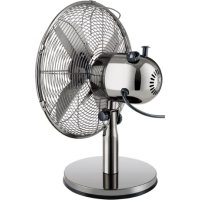
Exterior view of a Stebo air fan with four blades, mounted on a pole (no text or symbols on the fan itself)220-240V\~; 50/60Hz; 50W
Standventilator
VT S6
Instructions for use 12
Mode d'emploi 22
text_image
Technical diagram showing the assembly of a circular component with multiple parts and directional arrows indicating assembly steps.Montage Motorteil
text_image
T Unatural_image
Technical line drawing of a mechanical device with a circular component and a separate view showing a pin (no text or symbols)natural_image
Technical line drawing of a mechanical device with two views showing a bolt and connector (no text or symbols)natural_image
Technical line drawing of a mechanical device with three stages: before, after, and after assembly (no text or symbols)natural_image
Technical line drawing of a device with two views showing a mechanical component and a torque indicator (T), no text or symbols present.natural_image
Technical line drawings of a fan assembly process showing progressive assembly from fan to fan-like structure (no text or symbols)natural_image
Technical line drawing of a propeller with a blade and fan assembly (no text or symbols)natural_image
Technical line drawings of two circular fan components with radial blades and mounting brackets (no text or symbols)natural_image
Technical line drawing of a two-part fan with internal blades and a separate cutaway view showing a 2:1 ratio (no text or symbols)natural_image
Line drawing of a standard outdoor fan with a stand and vertical arm (no text or symbols)This appliance is for private and indoor use only and must not be used commercially. Please read the instruction manual carefully and keep it at a safe place. When the appliance is given to another person the instruction manual should be passed to that person, too. Only use the appliance as described in the instruction manual and pay attention to the safety information. No liability for damages or accidents will be accepted, which are caused by not paying attention to the instruction manual. Remove all packaging and sticker.
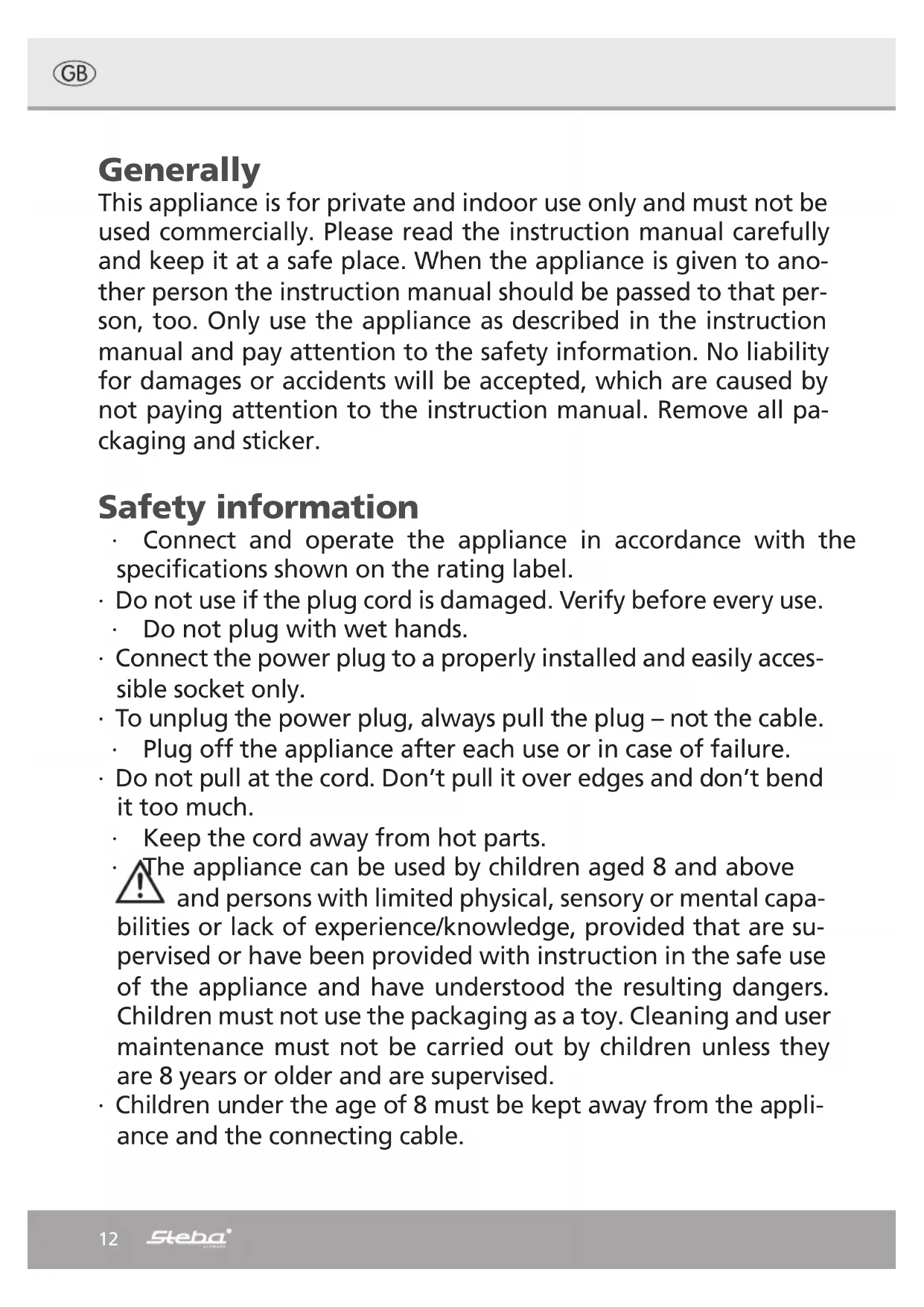
Safety information
- Connect and operate the appliance in accordance with the specifications shown on the rating label.
- Do not use if the plug cord is damaged. Verify before every use.
- Do not plug with wet hands.
- Connect the power plug to a properly installed and easily accessible socket only.
- To unplug the power plug, always pull the plug – not the cable.
- Plug off the appliance after each use or in case of failure.
- Do not pull at the cord. Don't pull it over edges and don't bend it too much.
- Keep the cord away from hot parts.
The appliance can be used by children aged 8 and above and persons with limited physical, sensory or mental capabilities or lack of experience/knowledge, provided that are supervised or have been provided with instruction in the safe use of the appliance and have understood the resulting dangers. Children must not use the packaging as a toy. Cleaning and user maintenance must not be carried out by children unless they are 8 years or older and are supervised.
- Children under the age of 8 must be kept away from the appliance and the connecting cable.
- Children should be supervised to ensure that they do not play with the appliance or packaging material (e.g. Plastic Bags).
- The appliance must not be operated using a timer or a separate remote system!
- Don't leave your home while the appliance is in function: ensure that the switch is in the OFF position.
- Do not leave the appliance outdoors or in a damp area.
- Never immerse the unit in water.
- Never use the device after a malfunction, e.g. if it felt down or has been damaged in any other manner.
- The manufacturer is not liable for damage which is occurring due to the usage of the appliance in a different way as described or a mistake in the handling has been made.
- To prevent injury, repairs such as replacing a damaged cord, should only be carried out by a customer service. Only original spare parts have to be used.
- Only use the device as described in this manual.
Do not direct the air flow from the device at flames (e.g. fireplaces, candles etc.), on babies or patients. Do not cover the intake or the outlet.
- Never plug something into the safe guard while the device is running.
- This appliance is intended to be used in household and similar applications such as:
o staff kitchen areas in shops, offices and others working environments
o by clients in hotels, motels and other residential type environments
o bed and breakfast type environments.
- If an extension cable is used, it has to have a cross-section of 1,5mm^2 . A cable drum must always be unwound.
- If a GS-tested 16 A multi-pin extension is used, it may not be charged with more than 3680 watts due to fire hazard.
- Make sure that children do not tease the cable or that a trip hazard occurs.
- The device must always be disconnected from the power supply if it is not supervised and before assembling, disassembling or cleaning.
Cleaning
Attention! Pull the plug before cleaning.
- Never immerse the unit into water.
- Use a humid cloth with a little bit of detergent to clean the housing.
- Clean dusty ventilation grilles with a vacuum cleaner.
Workplace
Important:
Never place this device on or next to hot surfaces (e.g. hot stoves). Only use it on a
even, stable and a heat resisting surface. It is important that no inflammable items are
near to the device. Do not place the device on the edge of the table so that it cannot be touched by children or fall down when touched.
Assembling the base and the standpipe

text_image
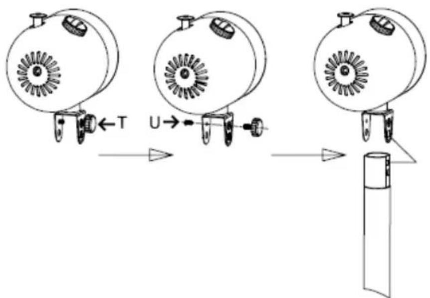
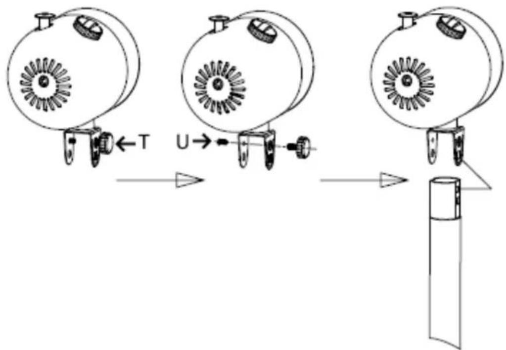
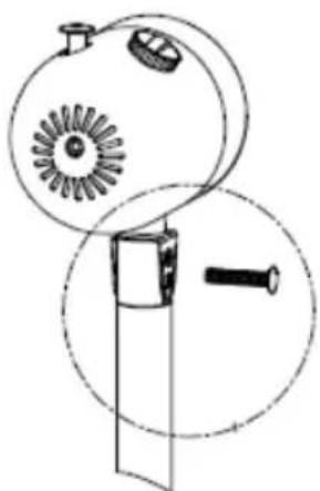
Technical diagram showing the assembly of a circular component with labeled parts and directional arrows indicating assembly steps.Assembling the motor part
text_image
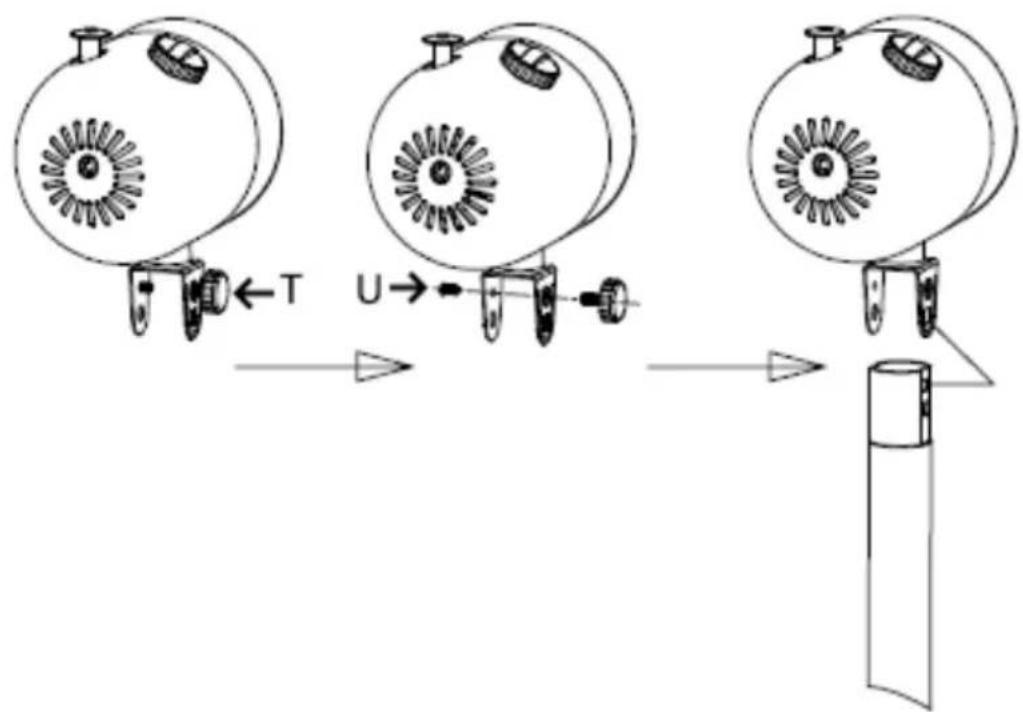
T U→Remove the screws T and U.
natural_image
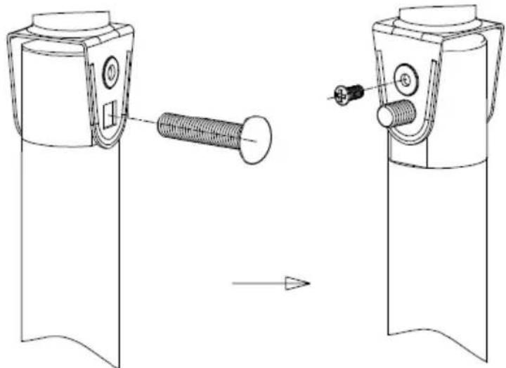
Technical line drawing of a mechanical device with circular components and a separate view showing a screw (no text or symbols)Place the motor part on the standpipe and insert the long collar screw.
natural_image
Technical line drawing of a mechanical device with a bolt and connector, showing two views (no text or symbols)Insert the square on the collar screw into the square hole on the housing. Then fix with the positioning screw U.
natural_image
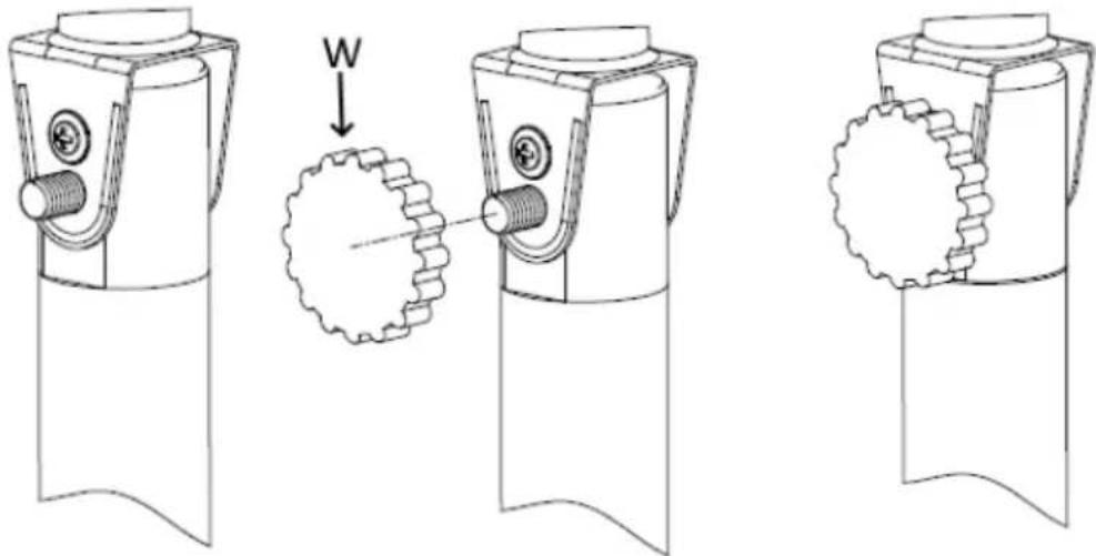
Technical line drawing of a mechanical device with three stages: before, after, and after assembly (no text or symbols)For fixing the motor part, screw on the knurled nut W.
natural_image
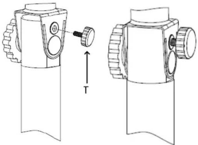
Technical line drawing of a device with two views showing a mechanical component and a torque indicator (T), no text or symbols present.Tighten the screw T.
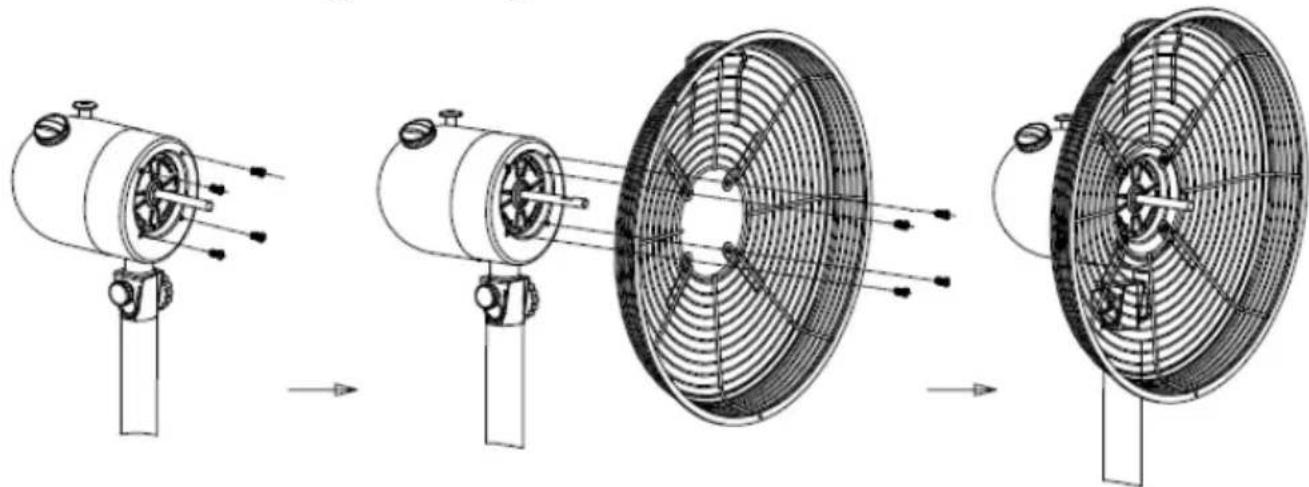
Assembling the grids and the rotor blades
natural_image
Technical line drawing of a fan assembly process showing progressive assembly from fan to fan blade (no text or labels)Remove the 4 screws on the motor part.
Screw the rear grid, with its handle upwards, on the motor part.
natural_image
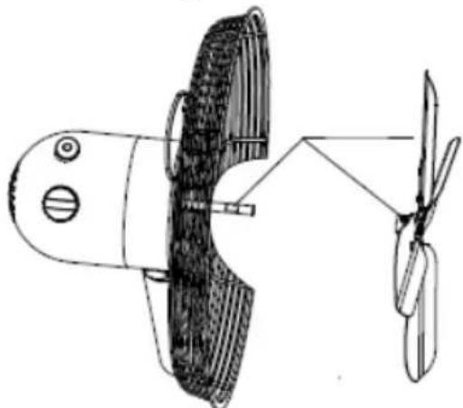
Technical line drawing of a mechanical device with two blades and a central blade (no text or symbols)Put on the rotor blades. The screw must be fixed in the axle flattening. The motor shaft must not protrude from the hub of the blades.

natural_image
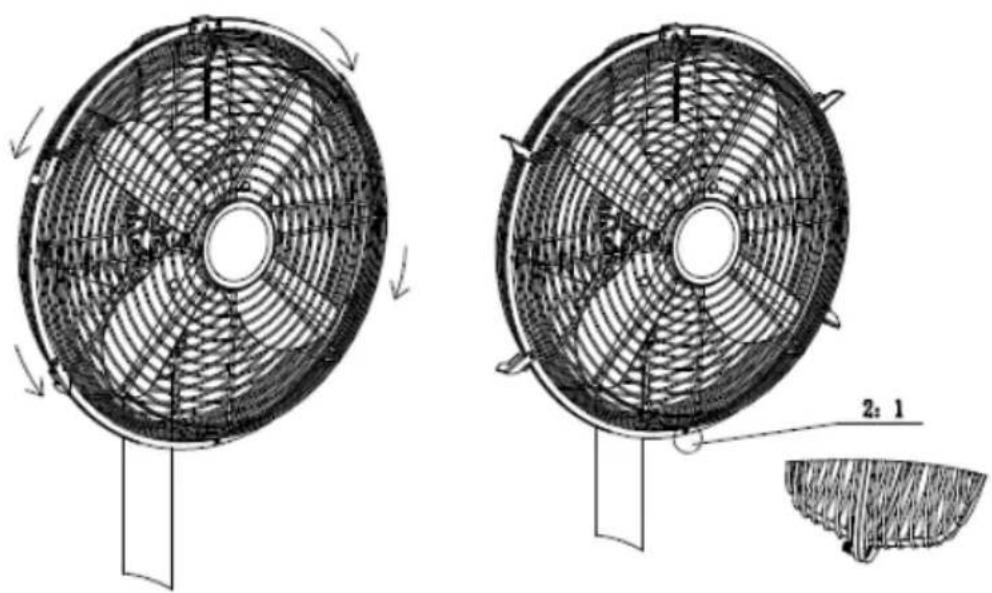
Technical line drawings of two circular fan structures with radial blades and mounting brackets (no text or symbols)Open the clips of the front grid and hook it in on the top of the device.
natural_image
Technical line drawing of a fan with internal blades and a separate cross-section showing a cut (no text or symbols)Fasten the front grid with screw and nut at the bottom. Then close the clips.
Functions
With the rotary switch you can choose different types of wind speed:
0 - Off
1 - low air flow
2 - medium air flow
3 - high air flow
The oscillation can be activated by pulling the handwheel on the motor part. By pushing it in again, the oscillation is deactivated.
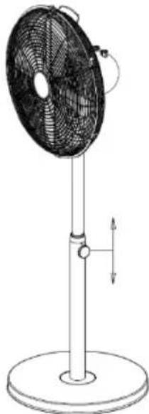
Height adjustment:
natural_image
Line drawing of a standard outdoor fan with a vertical post and base, showing no text or symbols.by loosening the screw, the height of the fan can be changed.
Inclination:
The angle of inclination can be adjusted upwards and downwards. To do this, hold the device on the standpipe and gently swivel the motor block to the desired position. Attention! Only press on the motor block, not on the grid!
Information requirements
| Steba VT S6 | |||
| Description Symbol Value | Unit | ||
| Maximum fan flow rate F 66,83 m | ^3/min | ||
| Fan power input P 47,0 W | |||
| Service value SV 1,42 (m | ^3/min)/W | ||
| Standby power consumption P | _SB - W | ||
| Fan sound power level | L_WA | 65,75 | dB(A) |
| Maximum air velocity | c | 3,6 | meters/sec |
| Measurement standard for service value | IEC 60879:1986(CORR.1992) | ||
| Contact details for obtaining more information | Steba Elektrogeräte GmbH & Co.KG Pointstr. 296129 Strullendorf | ||
Correct Disposal of this product
This marking indicates that this product should not be disposed with other household wastes throughout the EU. To prevent possible harm to the environment or human health from uncontrolled waste disposal, recycle it responsibly to promote the sustainable reuse of material resources. To return your used device, please use the return and collection systems or contact the retailer where the product was purchased. They can take this product for environmental safe recycling.
Packaging disposal: Do not throw away the package materials. Please put it in the recycling bin.
Gift box: Paper, should be put to the old paper collection point. Plastic packaging material and foils should be collected in the special collection containers.
Service and Repair:
If the appliance must be repaired, please get in touch with your trader or with the manufacturer:
text_image
Technical diagram showing the assembly of a circular component with multiple vertical supports and a base, labeled in Chinese.natural_image
Technical line drawing of a mechanical device with circular components and a separate view showing a pin (no text or symbols)natural_image
Technical line drawing of a mechanical device with a bolt and connector, showing assembly or alignment (no text or symbols)natural_image
Technical line drawing of a mechanical device with three stages: before, after, and after assembly (no text or symbols)natural_image
Technical line drawing of a device with two views showing a mechanical component and a torque indicator (T), no text or symbols present.natural_image
Four-step diagram showing the assembly of a fan blade and fan blade with internal blades, illustrating mechanical motion (no text or labels)natural_image
Technical line drawing of a mechanical device with two blades, one showing internal components and the other connected to a propeller (no text or symbols present)natural_image
Technical line drawings of two circular fan structures with radial blades and mounting brackets (no text or symbols)natural_image
Technical line drawing of a two-part fan with internal blades and a separate cutaway view showing a 2:1 ratio (no text or symbols)natural_image
Line drawing of a standard outdoor fan with a vertical post and base, showing no text or symbols.text_image
Technical diagram showing the assembly of a circular component with labeled parts and directional arrows indicating assembly steps.natural_image
Technical line drawing of a mechanical device with circular components and a separate inset showing a screw (no text or symbols)natural_image
Technical line drawing of a mechanical device with two views showing a bolt and connector (no text or symbols)natural_image
Technical line drawing of a mechanical device with three stages: before, after, and after assembly (no text or symbols)natural_image
Technical line drawing of a device with two views showing mechanical components and a torque indicator (T), no text or symbols present.natural_image
Technical line drawings of a fan assembly process showing progressive assembly from fan to fan-like structure (no text or symbols)natural_image
Technical line drawing of a mechanical device with two propellers and a blade, no text or symbols presentnatural_image
Technical line drawings of a circular fan or radiator component with internal grid patterns and directional arrows (no text or symbols)natural_image
Technical line drawing of a fan with internal blades and a separate close-up showing a cut section (no text or symbols)natural_image
Line drawing of a standard outdoor fan with a vertical post and base, showing no text or symbols.text_image
Technical diagram showing the assembly of a circular component with multiple vertical supports and a base, labeled in Chinese.Montage af Motordel
text_image
T U→natural_image
Technical line drawing of a mechanical device with circular components and a pin (no text or symbols)natural_image
Technical line drawing of two mechanical components with a screw and pin, showing assembly or alignment (no text or symbols)natural_image
Technical line drawing of a mechanical device with three stages: before, after, and after assembly (no text or symbols)sitionsskruen U.
natural_image
Technical line drawing of a device with two views showing a mechanical component and a torque indicator (T), no text or symbols present.Skru T-justeringsskuen fast.
natural_image
Technical line drawings of a fan assembly process showing progressive assembly from fan to fan-like structure (no text or symbols)natural_image
Technical line drawing of a mechanical device with two blades and a handle (no text or symbols)natural_image
Technical line drawings of two circular fan structures with radial blades and mounting brackets (no text or symbols)natural_image
Technical line drawing of a fan with internal blades and a separate cross-section showing a cut (no text or symbols)Fastgør det forreste gitter i bunden med skrue og møtrik. Luk derefter låsestroppen.