ZHP631G - Basket ZANUSSI - Free user manual and instructions
Find the device manual for free ZHP631G ZANUSSI in PDF.
User questions about ZHP631G ZANUSSI
0 question about this device. Answer the ones you know or ask your own.
Ask a new question about this device
Download the instructions for your Basket in PDF format for free! Find your manual ZHP631G - ZANUSSI and take your electronic device back in hand. On this page are published all the documents necessary for the use of your device. ZHP631G by ZANUSSI.
USER MANUAL ZHP631G ZANUSSI
INSTALLATION, USE AND MAINTENANCE HANDBOOK
MANUEL D'INSTRUCTIONS POUR L'INSTALLATION, L'EMPLOI ET L'ENTRETIEN
RECOMMENDATIONS AND SUGGESTIONS....10
CHARACTERISTICS....11
INSTALLATION 12
USE....14
MAINTENANCE....15
SOMMAIRE
FR
CONSEILS ET SUGGESTIONS 17
CARACTERISTIQUES 18
INSTALLATION 19
UTILISATION....21
ENTRETIEN....22
INHALTSVERZEICHNIS
DE
natural_image
Illustration of a kitchen appliance with a green X-shaped mark and a steaming pot on a base (no text or symbols)
natural_image
Illustration of a laboratory setup with a beaker and two piles of material, intersected by a green X-shaped line (no text or symbols)Ingombro

text_image
Ø 120 175 280 0÷152 598 - 898
text_image
Min. 500mm Min. 650mmComponenti
natural_image
Diagram of a device with green screen and directional arrows indicating movement or force (no text or symbols)Connessioni
USCITA ARIA VERSIONE ASPIRANTE
text_image
L M - V B-015natural_image
Illustration of a hand pointing at a green circular sign with a green arrow symbol (no text or numbers present)Filtri antiodore (Versione Filtrante)
SOSTITUZIONE
natural_image
Illustration of a hand pressing down on a mechanical component with a green arrow indicating direction (no text or symbols)Illuminazione
natural_image
Illustration of a hand holding a tool with a screwdriver, enclosed in a circular frame (no text or symbols)Illuminazione
natural_image
Illustration of a hand holding a small object with a green flag above it, no text or symbols present.The Instructions for Use apply to several versions of this appliance. Accordingly, you may find descriptions of individual features that do not apply to your specific appliance.
INSTALLATION
- The manufacturer will not be held liable for any damages resulting from incorrect or improper installation.
- The minimum safety distance between the cooker top and the extractor hood is 650 mm (some models can be installed at a lower height, please refer to the paragraphs on working dimensions and installation).
- Check that the mains voltage corresponds to that indicated on the rating plate fixed to the inside of the hood.
- For Class I appliances, check that the domestic power supply guarantees adequate earthing.
Connect the extractor to the exhaust flue through a pipe of minimum diameter 120 mm. The route of the flue must be as short as possible. - Do not connect the extractor hood to exhaust ducts carrying combustion fumes (boilers, fireplaces, etc.).
- If the extractor is used in conjunction with non-electrical appliances (e.g. gas burning appliances), a sufficient degree of aeration must be guaranteed in the room in order to prevent the backflow of exhaust gas. The kitchen must have an opening communicating directly with the open air in order to guarantee the entry of clean air.
USE
- The extractor hood has been designed exclusively for domestic use to eliminate kitchen smells.
- Never use the hood for purposes other than for which it has been designed.
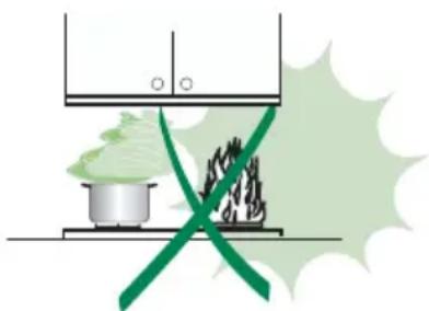
- Never leave high naked flames under the hood when it is in operation.
- Adjust the flame intensity to direct it onto the bottom of the pan only, making sure that it does not engulf the sides.
- Deep fat fryers must be continuously monitored during use: overheated oil can burst into flames.
- Do not flambè under the range hood; risk of fire
- This appliance is not intended for use by persons (including children) with reduced physical, sensory or mental capabilities, or lack of experience and knowledge, unless they have been given supervision or instruction concerning use of the appliance by a person responsible for their safety.
- Children should be supervised to ensure that they do not play with the appliance.
MAINTENANCE
- Switch off or unplug the appliance from the mains supply before carrying out any maintenance work.
- Clean and/or replace the Filters after the specified time period (Fire hazard).
- Clean the hood using a damp cloth and a neutral liquid detergent.
The symbol on the product or on its packaging indicates that this product may not be treated as household waste. Instead it shall be handed over to the applicable collection point for the recycling of electrical and electronic equipment. By ensuring this product is disposed of correctly, you will help prevent potential negative consequences for the environment and human health, which could otherwise be caused by inappropriate waste handling of this product. For more detailed information about recycling of this product, please contact your local city office, your household waste disposal service or the shop where you purchased the product.
natural_image
Illustration of a microwave oven with a green X-shaped exhaust cone and a steaming pot on the base (no text or symbols)
natural_image
Illustration of a laboratory setup with a beaker and two piles of green substances, crossed by a green diagonal line (no text or symbols)Dimensions
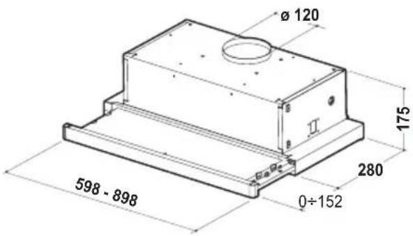
text_image
Ø 120 175 280 0÷152 598 - 898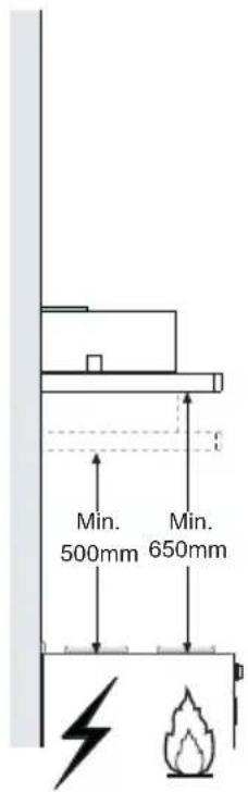
text_image
Min. 500mm Min. 650mmComponents
| Ref. | Q.ty | Product | Components |
| 1 | 1 | Hood | Body, complete with: Controls, Light, Blower, Filters |
| 8 | 1 | Directional | Air Outlet grille |
| 20 | 1 | Closing | element |
| Ref. | Q.ty | Installation | Components |
| 12a | 4 | Screws 4,2 x 44,4 | |
| 12e | 2 | Screws 2,9 x 9,5 |
| Q.ty | Documentation | |
| 1 | Instruction | Manual |
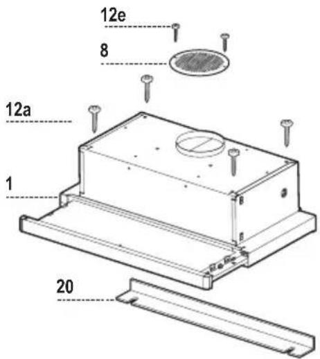
text_image
12e 8 12a 1 20Drilling the Support surface and Fitting the Hood
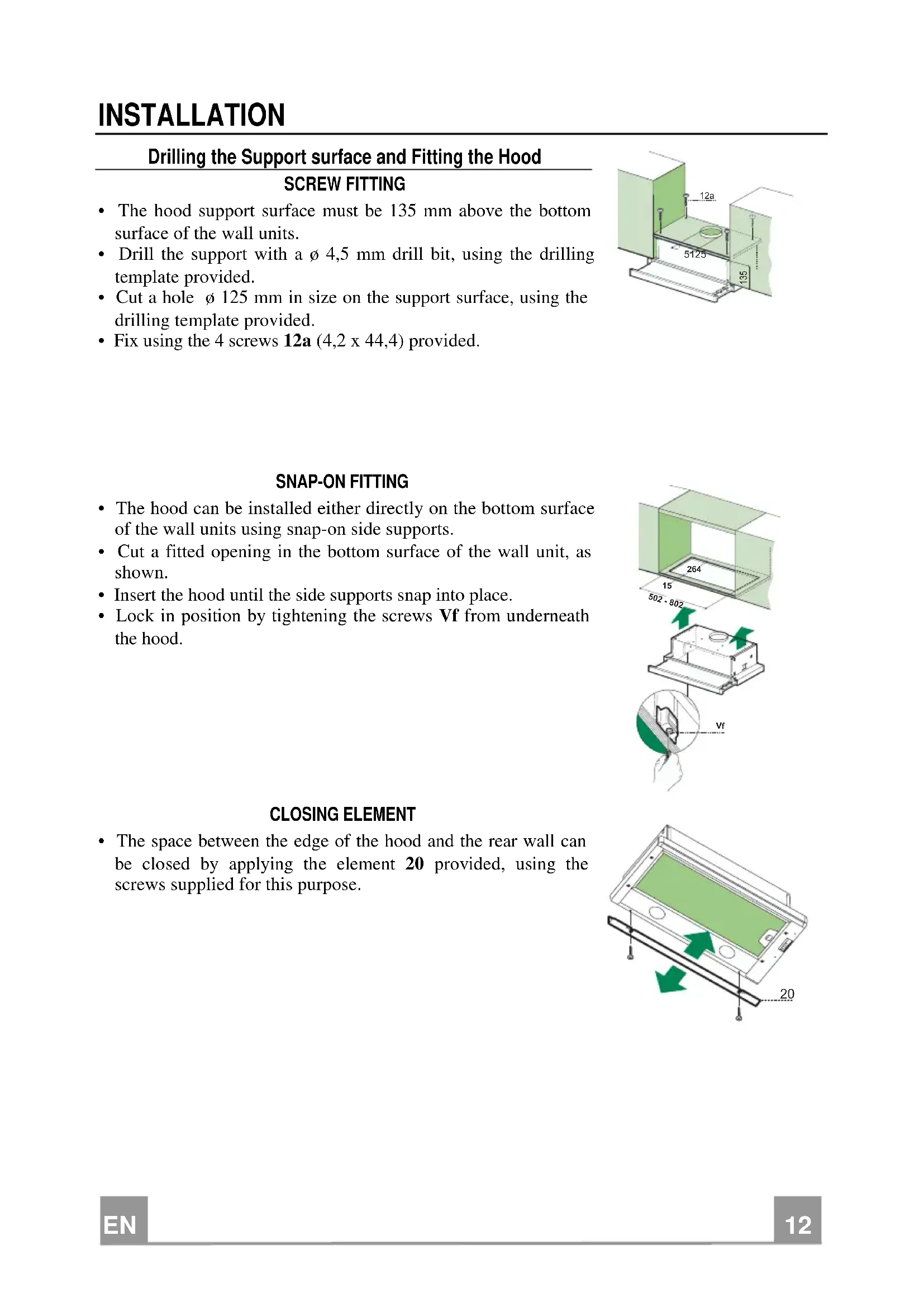
SCREW FITTING
- The hood support surface must be 135 mm above the bottom surface of the wall units.
- Drill the support with a 4,5 mm drill bit, using the drilling template provided.
- Cut a hole 125 mm in size on the support surface, using the drilling template provided.
• Fix using the 4 screws 12a (4,2 x 44,4) provided.
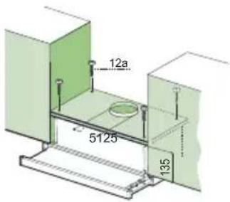
text_image
12a 5125 135SNAP-ON FITTING
- The hood can be installed either directly on the bottom surface of the wall units using snap-on side supports.
- Cut a fitted opening in the bottom surface of the wall unit, as shown.
- Insert the hood until the side supports snap into place.
- Lock in position by tightening the screws Vf from underneath the hood.
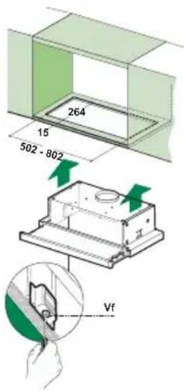
text_image
264 15 502 - 802 VfCLOSING ELEMENT
- The space between the edge of the hood and the rear wall can be closed by applying the element 20 provided, using the screws supplied for this purpose.

natural_image
Diagram of a device with green highlighted screen and directional arrows indicating movement or force (no text or symbols)Connections
DUCTED VERSION AIR EXHAUST SYSTEM
When installing the ducted version, connect the hood to the chimney using either a flexible or rigid pipe 120 mm, the choice of which is left to the installer.
- Fix the pipe in position using sufficient pipe clamps (not supplied).
- Remove any activated charcoal filters.
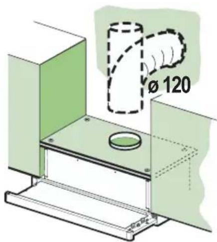
text_image
Ø 120RECIRCULATION VERSION AIR OUTLET
- Cut a hole 125 mm in any shelf that may be positioned over the hood.
- Connect the flange to the outlet on the shelf over the hood using a flexible or rigid pipe 120mm .
- Fix the pipe in position using sufficient pipe clamps (not supplied).
- Fix the directional grille 8 on the recirculation air outlet using the 2 screws 12e (2.9 x 9.5) provided.
- Ensure that the activated charcoal filters have been inserted.
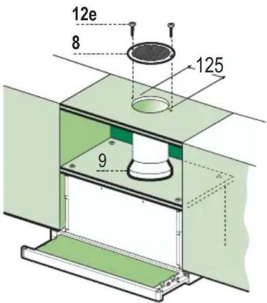
text_image
12e 8 125 9ELECTRICAL CONNECTION
- Connect the hood to the mains through a two-pole switch having a contact gap of at least 3 mm.
- When opening the sliding carriage for the first time after installing the hood, pull it out briskly until it clicks.
Control panel
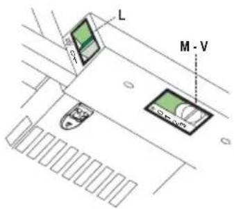
text_image
L M - VL Light Switches the lighting system on and off.
M Motor Switches the extractor motor on and off.
V Speed Sets the operating speed of the extractor:
-
Low speed, used for a continuous and silent air change in the presence of light cooking vapour.
-
Medium speed, suitable for most operating conditions given the optimum treated air flow/noise level ratio.
-
Maximum speed, used for eliminating the highest cooking vapour emission, including long periods.
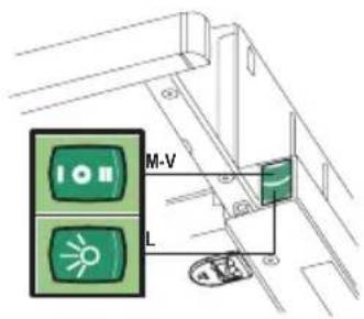
text_image
I ON M-V LL Light Switches the lighting system on and off.
M Motor Switches the extractor motor on and off.
V Speed Sets the operating speed of the extractor:
-
Low speed, used for a continuous and silent air change in the presence of light cooking vapour.
-
Medium speed, suitable for most operating conditions given the optimum treated air flow/noise level ratio.
Grease filters
CLEANING METAL CASSETTE GREASE FILTERS
- The filters must be cleaned every 2 months, or more frequently in case of particularly heavy use of the hood. Filters can be washed in a dishwasher.
- Pull out the sliding suction panel.
- Remove the filters one by one, after having disconnected the relative fastening elements.
- Wash the filters, taking care not to bend them. Let them get dry before refitting them. (The colour of the filter surface may change throughout the time but this has no influence to the filter efficiency).
- When refitting the filters, make sure that the handle is visible on the outside.
- Close the sliding suction panel.
natural_image
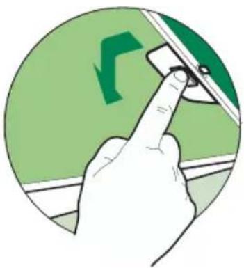
Illustration of a hand pointing at a green circular sign with a green arrow symbol (no text or numbers present)Charcoal filter (Recycling version)
REPLACING CHARCOAL FILTERS
- These filters are not washable and cannot be regenerated, and must be replaced approximately every four months or more frequently by particularly heavy use.
- Pull out the sliding suction panel.
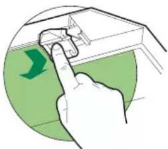
- Remove the grease filters.
- Remove the saturated carbon filter by releasing the fixing hooks
- Replace the grease filters.
- Close the sliding suction panel.
natural_image
Illustration of a hand pressing down on a mechanical component with a green arrow indicating direction (no text or symbols)Lighting
LIGHT REPLACEMENT
40 W incandescent light.
- Remove the metal grease filters.
- Unscrew the bulbs and replace them with new ones having the same characteristics.
- Replace the metal grease filters.
natural_image
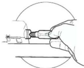
Line drawing of a hand holding a tool, no text or symbols presentLighting
LIGHT REPLACEMENT
20 W halogen light.
- Remove the 2 screws fixing the Lighting support, and pull it out of from the Hood.
• Extract the lamp from the Support. - Replace with another of the same type, making sure that the two pins are properly inserted in the lamp holder socket holes.
- Replace the Support, fixing it in place with the two screws removed as above.

natural_image
Illustration of a hand holding a small object with a green flag on top, no text or symbols presentnatural_image
Illustration of a microwave oven with a green X-shaped exhaust plume and a steaming pot on a base (no text or symbols)
natural_image
Illustration of a laboratory setup with a beaker, a beaker with green liquid, and a crossed glass (no text or symbols)natural_image
Diagram of a device with green screen and directional arrows indicating movement or force (no text or symbols)Branchements
SORTIE AIR VERSION EVACUATION
natural_image
Illustration of a hand pressing a car window on a green circular background (no text or symbols)Filtres anti-odeur (Version Filtrante)
REMLACEMENT
natural_image
Illustration of a hand pressing down on a mechanical component with a green arrow indicating direction (no text or symbols)Eclairage
REMLACEMENT LAMPES
natural_image
Line drawing of a hand holding a screwdriver with a tool, enclosed in a circular frame (no text or symbols)Eclairage
REMLACEMENT LAMPES
natural_image
Illustration of a hand holding a small object with a green flag on top, no text or symbols presentnatural_image
Illustration of a microwave oven with a green X-shaped exhaust plume and a steaming pot on the base (no text or symbols)
natural_image
Illustration of a laboratory setup with a beaker and two piles of green substances, separated by a green X-shaped barrier (no text or symbols)natural_image
Diagram of a device with green screen and directional arrows indicating movement or force (no text or symbols)Anschlüsse
natural_image
Illustration of a hand pressing a car safety camera on a green circular background (no text or symbols)natural_image
Illustration of a hand pressing down on a mechanical component with a green arrow indicating direction (no text or symbols)Beleuchtung
AUSWECHSELN DER LAMPEN
Glühlampen 40W
natural_image
Line drawing of a hand holding a tool, no text or symbols presentBeleuchtung
AUSWECHSELN DER LAMPEN
Halogenlampe 20 W
natural_image
Illustration of a hand holding a small object with a green flag on top, no text or symbols presentnatural_image
Illustration of a microwave oven with a green X-shaped exhaust cone and a steaming pot on a base (no text or symbols)