RNT - Microphone SE Electronics - Free user manual and instructions
Find the device manual for free RNT SE Electronics in PDF.

| Product Type | Large-diaphragm condenser tube microphone |
| Brand | SE Electronics |
| Model | RNT |
| Capsule | True 1-inch condenser, hand-made |
| Polar Patterns | 9 positions: omnidirectional, cardioid, figure-8, with 3 intermediate positions |
| Tube | 1 x 12AU7 (ECC82) hand-selected |
| Frequency Response | 20 Hz – 20 kHz |
| Sensitivity | 16 mV/Pa (-36 dBV) |
| Switched Gain | -12 / 0 / +12 dB |
| Max SPL | 151 dB SPL (0.5% THD) |
| Equivalent Noise | 18 dB(A) |
| Dynamic Range | 133 dB |
| Signal-to-Noise Ratio | 76 dB |
| Low-Cut Filter | 40 Hz / 80 Hz, 12 dB/octave, switchable |
| Output Impedance | 30 Ohms |
| Recommended Load Impedance | > 2 kOhms |
| Connector | 3-pin male XLR (power supply unit output) |
| Power Supply | Power supply unit / external power supply included (no phantom) |
| Dimensions (Microphone) | Diameter 62 mm, length 240 mm |
| Dimensions (Power Supply Unit) | 356 x 135 x 100 mm |
| Weight (Microphone) | 989 g |
| Weight (Power Supply Unit) | 3905 g |
| Included Accessories | Shock mount, 8-pin cable, IEC cable, wooden case, metal case, threaded adapter, manual |
| Maintenance | Clean with a dry cloth after use, store in the case |
| Safety | Do not use any power supply other than the one provided. Do not apply +48V phantom power. |
| Warranty | 5 years after online registration |
| Service and Repairability | Contact the dealer or sE Electronics customer service |
Frequently Asked Questions - RNT SE Electronics
User questions about RNT SE Electronics
0 question about this device. Answer the ones you know or ask your own.
Ask a new question about this device
Download the instructions for your Microphone in PDF format for free! Find your manual RNT - SE Electronics and take your electronic device back in hand. On this page are published all the documents necessary for the use of your device. RNT by SE Electronics.
USER MANUAL RNT SE Electronics
natural_image
Close-up of a black and white audio recording device with mesh grille and metallic shaft (no visible text or symbols)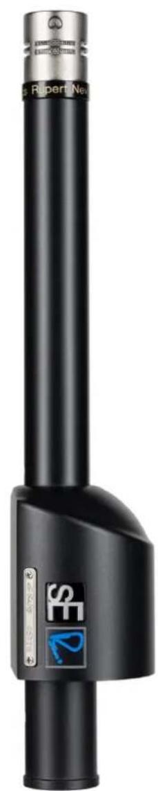
natural_image
Black cylindrical electronic device with metallic top and blue logo (no visible text or symbols)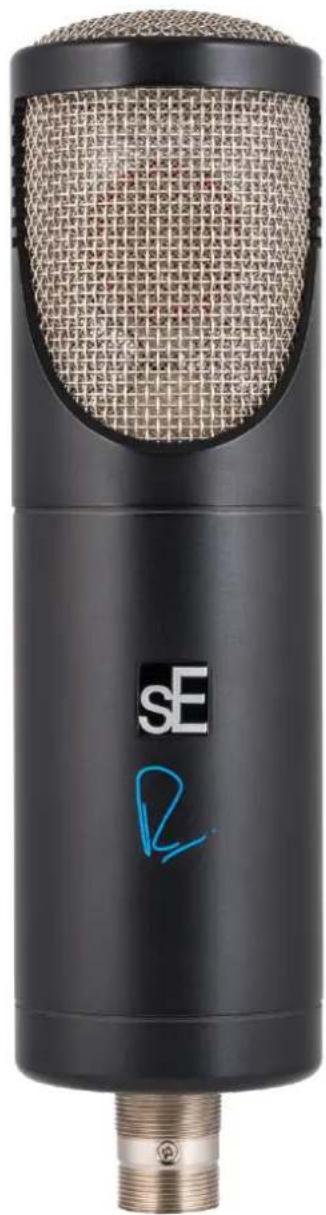
natural_image
Black and white photo of a black sE audio recording device with threaded port and textured grille (no visible text or symbols)Thank You
We would like to thank you cordially for choosing this sE / Rupert Neve microphone! This manual contains some important instructions for setting up and operating your new equipment. Please take a few minutes to read the instructions below carefully. We hope you will enjoy working with it as much as we enjoyed designing and building it for you.
Most Sincerely,
Your sE Team
Brief Descriptions
The RNR1
The RNR1 is an active ribbon microphone co-designed by sE Electronics and Rupert Neve Designs. It is the world's first ribbon microphone with a frequency response that extends all the way out to 25 kHz. Its 2.5μm aluminum ribbon is coupled to its class-A discrete internal circuitry through a custom-made Rupert Neve-designed transformer, and there is a second custom Rupert Neve-designed transformer on the microphone's output as well. The ribbon, transformers, and class-A electronics allow the RNR1 to "hear" deeply into a room in an extremely natural way, without the frequency response limitations of traditional ribbon microphones.
The RNR1's distinctive shape is not only eye-catching, but provides an ideal acoustic environment for the ribbon to perform its best – and the hand-crafted, hand-tuned ribbon element is surrounded by top-grade Neodymium magnets.
The switchable low-cut filter allows for removal of low-frequency rumble or footfall noise, or to reduce proximity effect.
The RNR1 comes standard with a shock-mount that will securely attach it to any mic stand and a wooden presentation case, all packaged inside a robust metal case.
The RN17
Co-designed with Mr. Rupert Neve, the RN17 is the world's first pencil microphone with a large-scale, hand-wound, ultra high-performance output transformer. This custom transformer was developed by Rupert Neve Designs to create a small-capsule microphone with exceptional warmth and low-frequency performance. The class-A electronics, also designed with Rupert Neve, provide exceptional amplification and low noise, and the gold-sputtered 15mm diaphragm in its capsule (17mm overall) provides excellent transient response and a very "immediate" sound.
The RN17 comes standard with a shock-mount that will securely attach it to any mic stand and a wooden presentation case, all packaged inside a robust metal case.
The RN17 is also available as a factory-matched Stereo Pair, with transformers and cardioid capsules factory-matched for perfect tolerance, guaranteeing the best possible stereo image. This configuration also includes a precision stereo mounting bar, two shock mounts, a wooden presentation case, and a secure metal case.
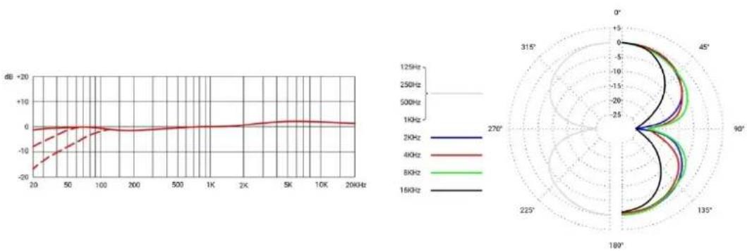
The RNT
The RNT is the third microphone in the collaboration between sE Electronics and Rupert Neve Designs, founded by the legendary audio designer Mr. Rupert Neve. Much like the RNR1 Active Ribbon and RN17 Small-Diaphragm Condenser, the RNT is something truly special, developed
over several years of careful listening and measurement by Mr. Rupert Neve, Mr. Siwei Zou, and the engineering teams from both Rupert Neve Designs and sE Electronics. All in all, the RNT brings the larger-than-life sounds of classic tube mics into the modern age with greater depth and clarity than ever before.
The RNT utilizes fully discrete, Class-A electronics throughout both of its active stages. The first stage is tube-based, with a hand-selected, low-noise 12AU7 tube within the microphone chassis, and implementing a custom-built Rupert Neve Designs output transformer. The second stage is within the floor box – which also controls polar pattern, filter and gain switching – and is built around the same custom op-amps used in Rupert Neve Designs' flagship 5088 recording console, known worldwide for its unrivaled transparency and headroom. This second stage is also coupled with a second custom-made Rupert Neve Designs output transformer.
The custom handcrafted large diaphragm true condenser capsule is sE's finest capsule yet, born from years of rigorous testing and listening, and developed and constructed by hand in sE's own factory. The Class-A electronics and switchable gain ensure a massive dynamic range, with high sound pressure level (SPL) handling capability and extremely low-noise components, and the switchable low-cut filters eliminate rumble or footfall noise, and can also compensate for an excess of bass frequencies caused by the proximity effect. This enables the RNT to close-mic many instruments including electric guitar speaker cabinets, brass instruments and drums. Lastly, the 9-position polar pattern switch allows for omnidirectional, cardioid, and figure-eight pickup patterns - and several positions in between each - for precise tailoring of the balance between direct and ambient sound when recording with the RNT.
Reliable operation is ensured by the sturdy all-metal design, robust construction, and high-quality manufacturing standards. A high-quality metal case is also included.
What's in the box
Your packaging should contain the follow items. If anything is missing, please contact your sE Electronics dealer and let them know.
| RNR1 | RN17 | RNT |
| RNR1 microphone | RN17 microphone* | RNT microphone |
| Custom shock-mount | Custom shock-mount* | Custom shock-mount |
| Wooden box | Wooden box | RNT Floor Box (Power Supply) |
| Metal case | Metal case | Wooden box |
| Thread adapter | Stereo mounting bar** | Metal case |
| User manual | Thread adapter* | 8-pin cable (to connect mic to floor box) |
| User manual | IEC power cable | |
| Thread adapter | ||
| User manual |
*two included with RN17 Matched Stereo Pair **included with Matched Stereo Pair only
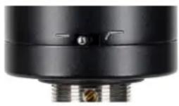
Controls (RNT)
The RNT floor box features a switch for the attenuation pads, a switch for the low-cut filters, and a switch for the polar pattern selection.
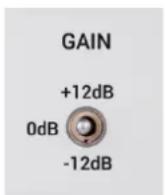
Gain Switch
The Gain Switch is located in the center of the floor box's front panel. When switched in, the incoming signal is either boosted (top position) or attenuated (bottom position) by 12dB, using custom Rupert Neve Designs op-amps to compensate for very loud or very quiet sound sources. Using the switch also helps prevent overloading the input stage of recording interfaces, mixing desks and microphone preamps.
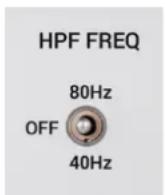
HPF FREQ Switch
The HPF FREQ Switch is located on the left side of the floor box's front panel, and inserts a low-cut filter at 80Hz (top position) or 40Hz (bottom position). The switch's center position removes the filter for a flat frequency response. Wind noise, plosives, footfall noise or rumble might affect the recorded signal, so enabling the low-cut filters reduces such unwanted noise and prevents distortion. Additionally, the low-cut filters also minimize the proximity effect when recording sound sources at a very short distance.
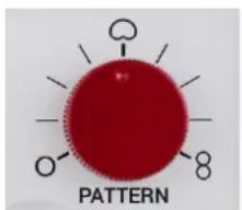
Pattern Switch
The 9-position Pattern Switch is located on the right side of the floor box's front panel, and allows the RNT's polar pattern to be changed from omnidirectional to cardioid to figure-eight, with three additional steps between each noted setting. This allows for great control over the balance between direct and ambient sound.
Controls (RNR1)
The RNR1 features a switchable low-cut filter, allowing for removal of low-frequency rumble or footfall noise, or to reduce proximity effect.
Powering (RNT)
The included floor box contains the outboard power supply for the RNT. No phantom power is required from an interface or microphone preamplifier.
Before powering on, connect all required cables (IEC to power, XLR to preamplifier or interface, and 8-pin cable from floor box to microphone). Then turn the power on via the switch on the back of the RNT floor box.
For best performance, we recommend allowing approximately 15 minutes of “warm up” time before recording. This allows the tube within the RNT to heat up and stabilize, and reduces the risk of unwanted noise or distortion on your recordings.

Risk of damage
Do not connect the microphone to any power supply other than the included RNT power supply. Do not apply phantom voltage (+48VDC) from an external interface or preamplifier. This is the only way to ensure safe and reliable operation.
Powering (RNR1, RN17)
To ensure proper operation, the microphone requires a phantom power source providing 48 Volts according to IEC 61938.

Risk of damage
Do not connect the microphone to any power supply other than a phantom power source (input with phantom power or external IEC standard phantom power supply) with a floating connector, using a balanced cable with studio grade connectors to IEC 268-12 only. This is the only way to ensure safe and reliable operation.
Safety and maintenance

Risk of damage
Please make sure that the piece of equipment to which your microphone and PSU will be connected fulfils the safety regulations enforced in your country and is fitted with a ground lead.
Cleaning the microphone
After every use, clean the microphone with a dry, soft cloth tissue and store it in a solid case or a zipper pouch.
Technical Specifications (RNT)
| Capsule | Hand-crafted 1" diaphragm true condenser capsule |
| Polar patterns | 9 (omni, cardioid, figure-8 with three additional steps between each) |
| Tube complement | 1x 12AU7 (ECC82) |
| Frequency range | 20 – 20,000 Hz |
| Sensitivity | 16 mV/Pa (-36 dBV) |
| Gain | -12 / 0 / +12 dB, switchable |
| Max. SPL (0.5% THD) | 151 dB_SPL |
| Equivalent noise level | 18 dB(A) |
| Dynamic range | 133 dB |
| Signal-to-noise ratio | 76 dB |
| Low cut filter | 40 / 80 Hz, 12 dB/Oct, switchable |
| Electrical impedance (floor box output) | 30 Ohms |
| Recommended load impedance | >2k Ohms |
| Connectivity | 3-pin male XLR connector |
| Power requirement | Floor Box / PSU (included) |
| Dimensions | MicrophoneDiameter 62 mm (2.44 in.) Length 240 mm (9.45 in.)Floor Box / PSU356 x 135 x 100 mm (14.02 x 5.31 x 3.94 in.) |
| Weight | Microphone989 g (34.90 oz.)Floor Box / PSU3905 g (137.79 oz.) |
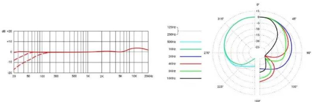
Omni
line
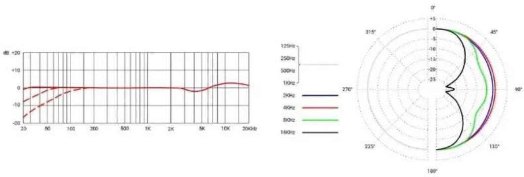
| Frequency | Value | | --------- | ----- | | 200Hz | -20 | | 200Hz | -10 | | 200Hz | 0 | | 200Hz | +10 | | 200Hz | +20 | | 400Hz | -10 | | 400Hz | -5 | | 400Hz | 0 | | 400Hz | +5 | | 400Hz | +15 | | 800Hz | -5 | | 800Hz | 0 | | 800Hz | +5 | | 800Hz | +15 | | 800Hz | +25 | | 1600Hz | -5 | | 1600Hz | 0 | | 1600Hz | +5 | | 1600Hz | +15 | | 1600Hz | +25 | | 270° | -5 | | 270° | 0 | | 270° | +5 | | 270° | +15 | | 270° | +25 | | 315° | -5 | | 315° | 0 | | 315° | +5 | | 315° | +15 | | 315° | +25 | | 45° | -5 | | 45° | 0 | | 45° | +5 | | 45° | +15 | | 45° | +25 | | 45° | +35 | | 90° | -5 | | 90° | 0 | | 90° | +5 | | 90° | +15 | | 90° | +25 | | 90° | +35 | | 135° | -5 | | 135° | 0 | | 135° | +5 | | 135° | +15 | | 135° | +25 | | 135° | +35 | | 180° | -5 | | 180° | 0 | | 180° | +5 | | 180° | +15 | | 180° | +25 | | 180° | +35 | | 225° | -5 | | 225° | 0 | | 225° | +5 | | 225° | +15 | | 225° | +25 | | 225° | +35 | | 270° | -5 | | 270° | 0 | | 270° | +5 | | 270° | +15 | | 270° | +25 | | 270° | +35 | | 315° | -5 | | 315° | 0 | | 315° | +5 | | 315° | +15 | | 315° | +25 | | 315° | +35 | | 45° | -5 | | 45° | 0 | | 45° | +5 | | 45° | +15 | | 45° | +25 | | 45° | +35 | | 90° | -5 | | 90° | 0 | | 90°-90% | -5 | | 90%-90% | -15 | | 90%-90% | -25 | | 90%-90% | -35 | | >90% | -5 | | >90% | -15 | | >90% | -25 | | >90% | -35 | | >90% | -45 | | >90% | >45 | | >90% | >60 | | >90% | >80 | | >90% | >160 | | >90% | >160 | | >90% | >31.5 | | >90% | >31.5 | | >90% | >61.7 | | >90% | >61.7 | | >90% | >81.7 | | >90% | >81.7 | | >90% | >161.7 | | >90% | >161.7 | | >90% | >31.7 | | >90% | >61.7 | | >90% | >81.7 | | >90% | >161.7 | | >90% | >31.7 | | >90% | >61.7 | | >90% | >81.7 | | >90% | >161.7 | | >90% | >31.7 | | >90% | >61.7 | | >90% | >81.7 | | >90% | >161.7 | | >90% | >31.7 | | >90% | >61.7 | | >90% | >81.7 | | >90% | >161.7 | | >90% | >31.7 (approx)| | >90% | >61.7 (approx)| | >90% | >81.7 (approx)| | >90% | >161.7 (approx)| | >90% | >31.7 (approx)| | >90% | >61.7 (approx)| | >90% | >81.7 (approx)| | >90% | >161.7 (approx)| | >90% | >31.7 (approx)| | >90% | >61.7 (approx)| | >89.7% | -5 | | >89.7% | -15 | | >89.7% | -5 | | >89.7% | +5 | | >89.7% | +15 | | >89.7% | +5 | | >89.7% | +15 | | >89.7% | +15 | | >89.7% | +25 | | >89.7% | +25 | | >89.7% | +35 | | >89.7% | +35 | | >89.7% | +45 | | >89.7% | >45 | | >89.7% | >61.7 | | >89.7% | >61.7 | | >89.7% | >81.7 | | >89.7% | >81.7 | | >89.7% | >161.7 | | >89.7% | >161.7 | | >89.7% | >31.7 | | >89.7% | >61.7 | | >89.7% | >81.7 | | >89.7% | >161.7 | | >89.7% | >31.7 | | <89.7% | -5 | | <89.7% | -15 | | <89.7% | -5 | | <89.7% | +5 | | <89.7% | +15 | | <89.7% | +5 | | <89.7% | +15 | | <89.7% | +15 | | <89.7% | +25 | | <89.7% | +25 | | <89.7% | +35 | | <89.7% | +35 | | <89.7% | >61.7 | | <89.7% | >61.7 | | <89.7% | >81.7 | | <89.7% | >81.7 | | <89.7% | >161.7 | | <89.7% | >161.7 | | <89.7% | >31.7 | | <89.7% | >61.7 | | <89.7% | >81.7 | | <89.7% | >161.7 | | <89.7% | >31.7 | | <89.7% | >61.7 | | <89.7% | >81.7 | | <89.7% | >161.7 | | <89.7% | -5 | | <89.7% | -15 | | <89.7% | -5 | | <89.7% | +5 | | <89.7% | +15 | | <89.7% | +5 | | <89.7% | +15 | | <89.7% | +15 | The chart displays the frequency response in dB for different frequencies (kHz) and their corresponding angular positions (degrees). The frequency values are labeled on the left axis.Wide Cardioid
line
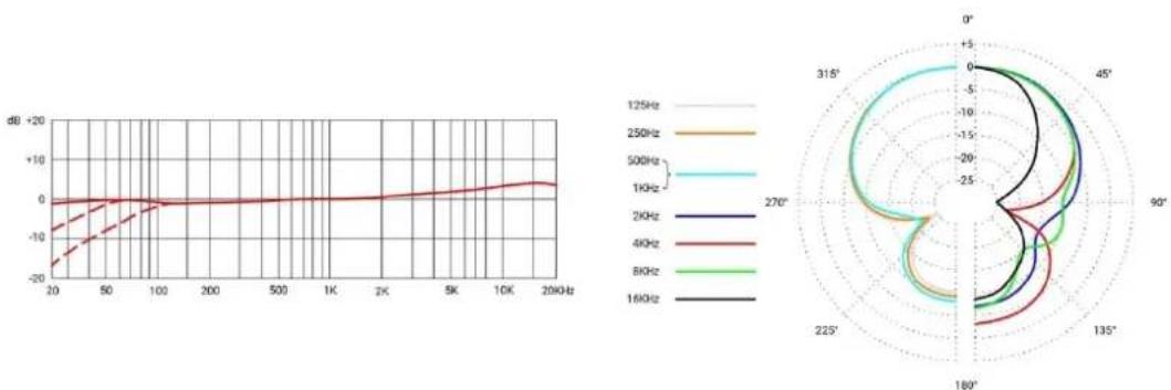
| Frequency | Angle (°) | | --------- | --------- | | 1KHz | 0° | | 2KHz | 45° | | 4KHz | 90° | | 8KHz | 135° | | 16KHz | 180° |Cardioid

line
| Frequency | Angle (°) | | --------- | --------- | | 125Hz | 0° | | 250Hz | 315° | | 500Hz | 45° | | 1KHz | 90° | | 2KHz | 135° | | 4KHz | 180° | | 8KHz | 225° | | 16KHz | 270° |Super Cardioid

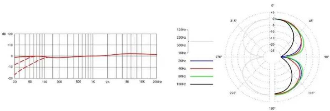
line
| Frequency | Value | | --------- | ----- | | 125Hz | 0 | | 250Hz | 0 | | 500Hz | 0 | | 1KHz | 0 | | 2KHz | 0 | | 4KHz | 0 | | 8KHz | 0 | | 16KHz | 0 |Figure-8
line
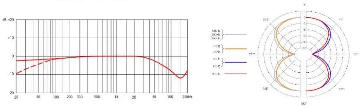
| Frequency | Angle (°) | Value (dB) | | --------- | --------- | ---------- | | 2KHz | 0° | -20 | | 2KHz | 45° | -10 | | 2KHz | 90° | -5 | | 2KHz | 135° | 0 | | 2KHz | 180° | 5 | | 2KHz | 225° | 10 | | 2KHz | 270° | 15 | | 4KHz | 0° | -10 | | 4KHz | 45° | -5 | | 4KHz | 90° | 0 | | 4KHz | 135° | 5 | | 4KHz | 180° | 10 | | 4KHz | 225° | 15 | | 4KHz | 270° | 20 | | 8KHz | 0° | -5 | | 8KHz | 45° | -10 | | 8KHz | 90° | -15 | | 8KHz | 135° | -20 | | 8KHz | 180° | -25 | | 8KHz | 225° | -30 | | 8KHz | 270° | -35 | | 15KHz | 0° | -5 | | 15KHz | 45° | -10 | | 15KHz | 90° | -15 | | 15KHz | 135° | -20 | | 15KHz | 180° | -25 | | 15KHz | 225° | -30 | | 15KHz | 270° | -35 | | Other | -20 | -20 | | Other | -10 | -10 | | Other | -5 | -5 | | Other | 0 | 0 | | Other | 5 | 5 | | Other | 10 | 10 | | Other | 15 | 15 | | Other | 20 | 20 | | Other | 25 | 25 | | Other | 30 | 30 | | Other | 35 | 35 | | Other | 40 | 40 | | Other | 45 | 45 | | Other | 50 | 50 | | Other | 55 | 55 | | Other | 60 | 60 | | Other | 65 | 65 | | Other | 70 | 70 | | Other | 75 | 75 | | Other | 80 | 80 | | Other | 85 | 85 | | Other | 90 | 90 | | Other | 95 | 95 | | Other | 100 | 100 | | Other | 105 | 105 | | Other | 110 | 110 | | Other | 115 | 115 | | Other | 120 | 120 | | Other | 125 | 125 | | Other | 130 | 130 | | Other | 135 | 135 | | Other | 140 | 140 | | Other | 145 | 145 | | Other | 150 | 150 | | Other | 155 | 155 | | Other | 160 | 160 | | Other | 165 | 165 | | Other | 170 | 170 | | Other | 175 | 175 | | Other | 180 | 180 | | Other | 185 | 185 | | Other | 190 | 190 | | Other | 195 | 195 | | Other | 200 | 200 | The chart displays a line graph of frequency response over a frequency range from -20 to +20 dB. The x-axis represents frequency in KHz (ranging from -20 to +20 dB), and the y-axis represents frequency in dB (ranging from -20 to +20 dB). The legend indicates four frequency bands: -2KHz, -4KHz, -8KHz, and +8KHz. The data is plotted as a line graph with color-coded bands for each band. The right radar plot shows the angular distribution of the same band. The angle values are labeled at the top of the chart.Technical Specifications (RNR1)
| Acoustic operating principle | Electrodynamic pressure gradient with active electronics |
| Transducer | Hand-tensioned 2.5μm aluminum ribbon |
| Polar pattern | Figure-8 |
| Frequency range | 20 Hz – 20 kHz |
| Sensitivity | 25 mV/Pa (-32 dB) |
| Max. SPL (0.5% THD @1kHz) | 137 dB_SPL |
| Signal to noise ratio | 77 dB |
| Self noise | 17 dB(A) |
| Low cut filter switch | 100 Hz |
| Power requirements | +48V phantom power |
| Electrical Impedance | 200 Ohms |
| Matching Connectors | XLR3F |
| Dimensions | 47mm (diameter) x 268mm (height) |
| Weight | 860g / 30.34oz |
Frequency response
line
| Frequency | Value (dB) | | --------- | ---------- | | 20 | -10 | | 50 | -5 | | 100 | 0 | | 200 | 0 | | 300 | 0 | | 500 | 0 | | 1K | 0 | | 2K | 0 | | 5K | -5 | | 10K | -10 | | 20K | -15 |Polar Pattern
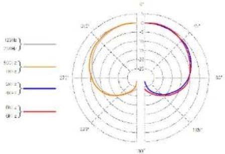
Technical Specifications (RN17)
| Capsule Type | Hand-Crafted True Condenser |
| Diaphragm | 17.2mm Gold/Mylar |
| Polar pattern | Cardioid (omnidirectional capsule available separately) |
| Frequency range | 20 Hz – 20 kHz |
| Sensitivity | 5.96 mV/Pa (-44.5dB) |
| Max. SPL (0.5% THD @1kHz) | 131 dB |
| Signal to noise ratio | 76 dB |
| Self noise | 18 dB(A) cardioid, 15 dB(A) omni |
| Power requirements | +48V phantom power |
| Electrical Impedance | 200 Ohms |
| Matching Connectors | XLR3F |
| Diameter | 44 mm (transformer), 17 mm (capsule) |
| Length | 200 mm |
| Weight | 320 g / 11.32 oz |
| Stereo Bar (Matched Stereo Pair Only) | |
| Weight | 245 g / 8.64 oz |
| Dimensions | 300 x 25 mm |
| Max. width between mic mounts | 276 mm |
| Min. width between mic mounts | 58 mm |
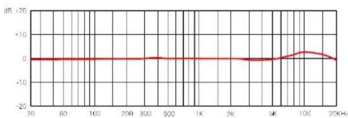
Frequency response
line
| Frequency | Value | | --------- | ----- | | 20 | 0 | | 50 | 0 | | 100 | 0 | | 200 | 0 | | 300 | 0 | | 500 | 0 | | 1K | 0 | | 2K | 0 | | 5K | 0 | | 10K | 2 | | 20K | 0 |Polar Pattern
Support
In case you are experiencing any problems or have any questions regarding your sE product, please contact your dealer first for the fastest and more direct service. If an authorized service is required, it will be arranged by that dealer: http://www.seelectronics.com/dealers
If you still have difficulties with support or assistance, please do not hesitate to contact us directly: http://www.seelectronics.com/contact-us
Lastly, remember to register your new gear to extend your warranty to a full five years: http://www.seelectronics.com/registration
Contact
Feel free to contact us:
sE Electronics International, Inc.
www.seelectronics.com
448 Ignacio Blvd, STE 411 contact@seelectronics.com
Novato, CA 94949
USA
Our international distributors & sales representatives: http://www.seelectronics.com/contact-us
This product conforms to the standards listed in the Declaration of Conformity. Please contact us if you want to order a free copy of the Declaration of Conformity. Technical data subject to change without notice.
Danke
Beschädigungsgefahr
http://www.seelectronics.com/registration
radar
| Angle | 120° (Z) | 500° (Z) | 360° (Z) | 90° (Z) | |---|---|---|---|---| | 0°-45° | 18.5 | 17.8 | 16.2 | 15.5 | | 45°-80° | 18.5 | 17.8 | 16.2 | 15.5 | | 80°-125° | 18.5 | 17.8 | 16.2 | 15.5 | | 125°-180° | 18.5 | 17.8 | 16.2 | 15.5 | | 180°-235° | 18.5 | 17.8 | 16.2 | 15.5 | | 235°-290° | 18.5 | 17.8 | 16.2 | 15.5 | | 290°-345° | 18.5 | 17.8 | 16.2 | 15.5 | | 345°-390° | 18.5 | 17.8 | 16.2 | 15.5 | | 390°-445° | 18.5 | 17.8 | 16.2 | 15.5 | | 445°-490° | 18.5 | 17.8 | 16.2 | 15.5 | | 490°-545° | 18.5 | 17.8 | 16.2 | 15.5 | | 545°-600° | 18.5 | 17.8 | 16.2 | 15.5 | | 600°-655° | 18.5 | 17.8 | 16.2 | 15.5 | | 655°-710° | 18.5 | 17.8 | 16.2 | 15.5 | | 710°-765° | 18.5 | 17.8 | 16.2 | 15.5 | | 765°-820° | 18.5 | 17.8 | 16.2 | 15.5 | | 820°-875° | 18.5 | 17.8 | 16.2 | 15.5 | | 875°-930° | 18.5 | 17.8 | 16.2 | 15.5 | | 930°-985° | 18.5 | 17.8 | 16.2 | 15.5 | | 985°-1040° | 18.5 | 17.8 | 16.2 | 15.5 | | 1040°-1095° | 18.5 | 17.8 | 16.2 | 15.5 | | 1095°-1140° | 18.5 | 17.8 | 16.2 | 15.5 | | 1140°-1195° | 18.5 | 17.8 | 16.2 | 15.5 | | 1195°-1240° | 18.5 | 17.8 | 16.2 | 15.5 | | 1240°-1295° | 18.5 | 17.8 | 16.2 | 15.5 | | 1295°-1340° | 18.5 | 17.8 | 16.2 | 15.5 | | 1340°-1395° | 18.5 | 17.8 | 16.2 | 15.5 | | 1395°-1440° | 18.5 | 17.8 | 16.2 | 15.5 | | 1440°-1495° | 18.5 | 17.8 | 16.2 | 15.5 | | 1495°-1540° | 18.5 | 17.8 | 16.2 | 15.5 | | 1540°-1600° | 18.5 | 17.8 | 16.2 | 15.5 | | Note: The last row is a duplicate label (e.g., '90' or '360') to close the circle in the image, but the values for the last row are estimated based on the visual scale and the label 'Z' in the legend.Supporto
line
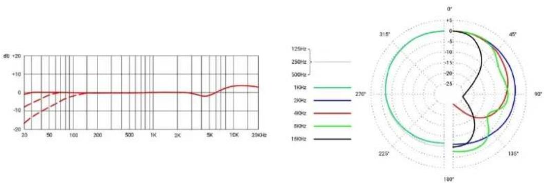
| Frequency | Value | | --------- | ----- | | 200Hz | -20 | | 200Hz | -10 | | 200Hz | 0 | | 200Hz | +10 | | 200Hz | +20 | | 400Hz | -10 | | 400Hz | -5 | | 400Hz | 0 | | 400Hz | +5 | | 400Hz | +15 | | 800Hz | -5 | | 800Hz | 0 | | 800Hz | +5 | | 800Hz | +15 | | 800Hz | +25 | | 1600Hz | -5 | | 1600Hz | 0 | | 1600Hz | +5 | | 1600Hz | +15 | | 1600Hz | +25 | | 270° | -5 | | 270° | 0 | | 270° | +5 | | 270° | +15 | | 270° | +25 | | 315° | -5 | | 315° | 0 | | 315° | +5 | | 315° | +15 | | 315° | +25 | | 45° | -5 | | 45° | 0 | | 45° | +5 | | 45° | +15 | | 45° | +25 | | 45° | +35 | | 90° | -5 | | 90° | 0 | | 90° | +5 | | 90° | +15 | | 90° | +25 | | 90° | +35 | | 135° | -5 | | 135° | 0 | | 135° | +5 | | 135° | +15 | | 135° | +25 | | 135° | +35 | | 180° | -5 | | 180° | 0 | | 180° | +5 | | 180° | +15 | | 180° | +25 | | 180° | +35 | | 225° | -5 | | 225° | 0 | | 225° | +5 | | 225° | +15 | | 225° | +25 | | 225° | +35 | | 270° | -5 | | 270° | 0 | | 270° | +5 | | 270° | +15 | | 270° | +25 | | 270° | +35 | | 315° | -5 | | 315° | 0 | | 315° | +5 | | 315° | +15 | | 315° | +25 | | 315° | +35 | | 45° | -5 | | 45° | 0 | | 45° | +5 | | 45° | +15 | | 45° | +25 | | 45° | +35 | | 90° | -5 | | 90° | 0 | | 90°-90% | -5 | | 90%-90% | -15 | | 90%-90% | -25 | | 90%-90% | -35 | | >90% | -5 | | >90% | -15 | | >90% | -25 | | >90% | -35 | | >90% | -45 | | >90% | >45 | | >90% | >60 | | >90% | >80 | | >90% | >160 | | >90% | >160 | | >90% | >31.5 | | >90% | >31.5 | | >90% | >61.7 | | >90% | >61.7 | | >90% | >81.7 | | >90% | >81.7 | | >90% | >161.7 | | >90% | >161.7 | | >90% | >31.7 | | >90% | >61.7 | | >90% | >81.7 | | >90% | >161.7 | | >90% | >31.7 | | >90% | >61.7 | | >90% | >81.7 | | >90% | >161.7 | | >90% | >31.7 | | >90% | >61.7 | | >90% | >81.7 | | >90% | >161.7 | | >90% | >31.7 | | >90% | >61.7 | | >90% | >81.7 | | >90% | >161.7 | | >90% | >31.7 (approx)| | >90% | >61.7 (approx)| | >90% | >81.7 (approx)| | >90% | >161.7 (approx)| | >90% | >31.7 (approx)| | >90% | >61.7 (approx)| | >90% | >81.7 (approx)| | >90% | >161.7 (approx)| | >90% | >31.7 (approx)| | >90% | >61.7 (approx)| | >89.7% | -5 | | >89.7% | -15 | | >89.7% | -5 | | >89.7% | +5 | | >89.7% | +15 | | >89.7% | +5 | | >89.7% | +15 | | >89.7% | +15 | | >89.7% | +25 | | >89.7% | +25 | | >89.7% | +35 | | >89.7% | +35 | | >89.7% | +45 | | >89.7% | >45 | | >89.7% | >61.7 | | >89.7% | >61.7 | | >89.7% | >81.7 | | >89.7% | >81.7 | | >89.7% | >161.7 | | >89.7% | >161.7 | | >89.7% | >31.7 | | >89.7% | >61.7 | | >89.7% | >81.7 | | >89.7% | >161.7 | | >89.7% | >31.7 | | <89.7% | -5 | | <89.7% | -15 | | <89.7% | -5 | | <89.7% | +5 | | <89.7% | +15 | | <89.7% | +5 | | <89.7% | +15 | | <89.7% | +15 | | <89.7% | +25 | | <89.7% | +25 | | <89.7% | +35 | | <89.7% | +35 | | <89.7% | >61.7 | | <89.7% | >61.7 | | <89.7% | >81.7 | | <89.7% | >81.7 | | <89.7% | >161.7 | | <89.7% | >161.7 | | <89.7% | >31.7 | | <89.7% | >61.7 | | <89.7% | >81.7 | | <89.7% | >161.7 | | <89.7% | >31.7 | | <89.7% | >61.7 | | <89.7% | >81.7 | | <89.7% | >161.7 | | <89.7% | -5 | | <89.7% | -15 | | <89.7% | -5 | | <89.7% | +5 | | <89.7% | +15 | | <89.7% | +5 | | <89.7% | +15 | | <89.7% | +15 | The chart displays the frequency response in dB for different frequencies (kHz) and their corresponding angular positions (degrees). The frequency values are labeled on the left axis.Cardioïde Large

line
| Frequency | Angle (°) | | --------- | --------- | | 1KHz | 0° | | 2KHz | 90° | | 4KHz | 180° | | 8KHz | 270° | | 16KHz | 315° |Cardioïde
line
| Frequency | Value | | --------- | ----- | | 125Hz | -20 | | 250Hz | -10 | | 500Hz | 0 | | 1KHz | 0 | | 2KHz | 0 | | 4KHz | 0 | | 8KHz | 0 | | 16KHz | 0 |Super Cardioïde
line
| Frequency | Value | | --------- | ----- | | 125Hz | 0 | | 250Hz | 0 | | 500Hz | 0 | | 1KHz | 0 | | 2KHz | 0 | | 4KHz | 0 | | 8KHz | 0 | | 16KHz | 0 |Figure-8
line
| Frequency | Angle (°) | Value (dB) | | --------- | --------- | ---------- | | 2KHz | 0° | -20 | | 2KHz | 45° | -10 | | 2KHz | 90° | -5 | | 2KHz | 135° | 0 | | 2KHz | 180° | 5 | | 2KHz | 225° | 10 | | 2KHz | 270° | 15 | | 2KHz | 315° | 20 | | 4KHz | 0° | -10 | | 4KHz | 45° | -5 | | 4KHz | 90° | 0 | | 4KHz | 135° | 5 | | 4KHz | 180° | 10 | | 4KHz | 225° | 15 | | 4KHz | 270° | 20 | | 4KHz | 315° | 25 | | 8KHz | 0° | -5 | | 8KHz | 45° | -10 | | 8KHz | 90° | -15 | | 8KHz | 135° | -20 | | 8KHz | 180° | -25 | | 8KHz | 225° | -30 | | 8KHz | 270° | -35 | | 8KHz | 315° | -40 | | 15KHz | 0° | -5 | | 15KHz | 45° | -10 | | 15KHz | 90° | -15 | | 15KHz | 135° | -20 | | 15KHz | 180° | -25 | | 15KHz | 225° | -30 | | 15KHz | 270° | -35 | | 15KHz | 315° | -40 | | Note: The angle values are labeled as '0' to '315'. The data is presented in a CSV format with three columns: Frequency (GHz) and Angle (degrees).Spécifications techniques (RNR1)
Riesgo de daños
Technical Specifications (RNR1)
radar
| Angle | 12Hz | 20Hz | 30Hz | 40Hz | 80Hz | 100Hz | |---|---|---|---|---|---|---| | 0° | 0 | 0 | 0 | 0 | 0 | 0 | | 30° | 0 | 0 | 0 | 0 | 0 | 0 | | 60° | 0 | 0 | 0 | 0 | 0 | 0 | | 90° | 0 | 0 | 0 | 0 | 0 | 0 | | 120° | 0 | 0 | 0 | 0 | 0 | 0 | | 150° | 0 | 0 | 0 | 0 | 0 | 0 | | 180° | 0 | 0 | 0 | 0 | 0 | 0 | | 215° | 0 | 0 | 0 | 0 | 0 | 0 | | 250° | 0 | 0 | 0 | 0 | 0 | 0 | | 285° | 0 | 0 | 0 | 0 | 0 | 0 | | 315° | 0 | 0 | 0 | 0 | 0 | 0 | | 345° | 0 | 0 | 0 | 0 | 0 | 0 | | 375° | 0 | 0 | 0 | 0 | 0 | 0 | | 415° | 0 | 0 | 0 | 0 | 0 | 0 | | 445° | 0 | 0 | 0 | 0 | 0 | 0 | | 485° | 0 | 0 | 0 | 0 | 0 | 0 | | 525° | 0 | 0 | 0 | 0 | 0 | 0 | | 565° | 0 | 0 | 0 | 0 | 0 | 0 | | 615° | 0 | 0 | 0 | 0 | 0 | 0 | | Note: The last row is a duplicate of the first row to close the circle in the radar chart. The rest of the chart is a duplicate of the original data point.Technical Specifications (RN17)
http://www.seelectronics.com/registration
Contacto
radar
| Category | Value | |---|---| | 1238E | 2.999 | | 500E | 1.000 | | 285E | 1.000 | | 487E | 1.000 | | 487E | 1.000 | | 487E | 1.000 | | 487E | 1.000 | | 487E | 1.000 | | 487E | 1.000 | | 487E | 1.000 | | 487E (radial axis) | 1.000 | | 487E (radial axis) | 1.000 | | 487E (radial axis) | 1.000 | | 487E (radial axis) | 1.000 | | 487E (radial axis) | 1.000 | | 487E (radial axis) | 1.500 | | 487E (radial axis) | 1.500 | | 487E (radial axis) | 1.500 | | 487E (radial axis) | 1.500 | | 487E (radial axis) | 1.500 | | 487E (radial axis) | 1.500 | | Note: The values in the 'radial axis' column are estimated based on the provided code and are not explicitly labeled in the image. The values in the 'radial axis' column are estimated based on the provided code and are estimated based on the given label '1238E'.Поддержка
sE Electronics International, Inc.
448 Ignacio Blvd, STE 411 contact@seelectronics.com
Novato, CA 94949
США
www.seelectronics.com
Thank you for purchasing an sE / Rupert Neve product! You are automatically entitled to a four-year warranty, but can extend this to a full five years with registration. To register your new equipment and to read the full warranty details, please go here:
http://www.seelectronics.com/registration
Most Sincerely,
Your sE Team