PDU3VN10L1530B - Power strip Tripp Lite - Free user manual and instructions
Find the device manual for free PDU3VN10L1530B Tripp Lite in PDF.
User questions about PDU3VN10L1530B Tripp Lite
0 question about this device. Answer the ones you know or ask your own.
Ask a new question about this device
Download the instructions for your Power strip in PDF format for free! Find your manual PDU3VN10L1530B - Tripp Lite and take your electronic device back in hand. On this page are published all the documents necessary for the use of your device. PDU3VN10L1530B by Tripp Lite.
USER MANUAL PDU3VN10L1530B Tripp Lite
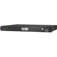
3-Phase Monitored 0U Power Distribution Units
(Phase and Bank Measurements)
208V MODELS
PDU3VN6L2120
PDU3VN6L2130
PDU3VN6G30B
(Series Number: AG-00B8)
(Series Number: AG-00B9)
(Series Number: AG-00BA)
PDU3VN6L1530B ••
PDU3VN10L1530B
PDU3VN6L2130B
(Series Number: AG-00BA)
(Series Number: AG-00BA)
(Series Number: AG-00BA)
PDU3VN6H50B
PDU3VN6G60B
PDU3VN6G60C
(Series Number: AG-00BA)
(Series Number: AG-00BA)
(Series Number: AG-00BB)
400V MODEL
PDU3XVN6G20
(Series Number: AG-00BD)
Important Safety Instructions 2
Service 18
Installation 3
Warranty and 19
Digital Display 6
Product Registration
Using the Digital Display 9
Español 20
Features 16
Français 39
Configuration and Operation 18
Русский 58
PROTECT YOUR INVESTMENT!
Register your product for quicker service and ultimate peace of mind.
You could also win an ISOBAR6ULTRA surge protector— a \$100 value!

text_image
QR code image containing encoded data, no visible human-readable textwww.tripplite.com/warranty

text_image
TRIPP·LITE
Manufacturing Excellence.
1111 W. 35th Street, Chicago, IL 60609 USA • www.tripplite.com/support
Copyright © 2015 Tripp Lite. All rights reserved.
Important Safety Instructions

SAVE THESE INSTRUCTIONS
This manual contains instructions and warnings that should be followed during the installation, operation, and storage of this product. Failure to heed these instructions and warnings may affect the product warranty.
- The PDU provides the convenience of multiple outlets, but DOES NOT provide surge or line noise protection for connected equipment.
- The PDU is designed for indoor use only, in a controlled environment, away from excess moisture, temperature extremes, conductive contaminants, dust or direct sunlight.
- Keep indoor ambient temperature between 32^ and 122^ (0°C and 50°C).
- The PDU must be installed by a qualified technician only.
- Do not attempt to mount the PDU to an insecure or unstable surface.
• Install in accordance with National Electrical Code standards. Be sure to use the proper overcurrent protection for the installation, in accordance with the plug/equipment rating. - Connect the PDU to an outlet that is in accordance with your local building codes and that is adequately protected against excess currents, short circuits and earth faults.
- The electrical outlets supplying power to the equipment should be installed near the equipment and easily accessible.
- Do not connect the PDU to an ungrounded outlet or to extension cords or adapters that eliminate the connection to ground.
- Be sure to provide a local disconnect device on any models that are permanently installed without a plug that is easily accessible.
- Never attempt to install electrical equipment during a thunderstorm.
- Individual equipment connected to the PDU should not draw more current than the individual PDU's outlet's rating.
- The total load connected to the PDU must not exceed the maximum load rating for the PDU.
- Do not attempt to modify the PDU, input plugs or power cables.
- Do not drill into or attempt to open any part of the PDU housing. There are no user-serviceable parts inside.
- Do not attempt to use the PDU if any part of it becomes damaged.
- Use of this equipment in life support applications where failure of this equipment can reasonably be expected to cause the failure of the life support equipment or to significantly affect its safety or effectiveness is not recommended. Do not use this equipment in the presence of a flammable anesthetic mixture with air, oxygen or nitrous oxide.
Installation
Mounting the PDU
Note: The illustrations may differ somewhat from your PDU model. Regardless of configuration, the user must determine the fitness of hardware and procedures before mounting. The PDU and included hardware are designed for common rack and rack enclosure types and may not be appropriate for all applications. Exact mounting configurations may vary. Screws for attaching the mounting brackets to the PDU are included. Use only the screws supplied by the manufacturer or their exact equivalent.
Note: Mounting buttons come preinstalled to the PDU for toolless mounting.

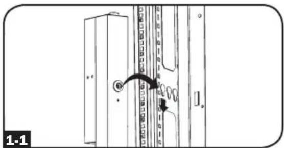
To mount the PDU using the pre-installed mounting buttons, position the PDU as desired in the rack enclosure, align the buttons with the rack mounting slots, and slide the PDU into position.

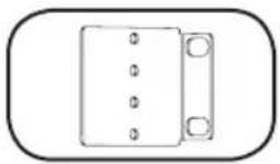
To attach the mounting brackets to the PDU, remove the mounting buttons.

Attach the mounting brackets to the PDU with the included screws.

Attach the PDU to a vertical rail in your rack or rack enclosure. (Use the mounting hardware that came with your rack or rack enclosure to attach the mounting brackets to the rail.)

To reinstall the mounting buttons for toolless mounting, remove the mounting brackets then install the mounting buttons onto the PDU.
Note: Be sure to insert the 2 buttons into either the upper hole at each end of the PDU or into the lower hole at each end of the PDU.

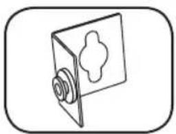
To install the PDU with its outlets facing the rear of the rack, use the included PDUMVROTATEBRKT accessory. First, attach the mounting button A to the V-shaped bracket B using the included screw and washer. Then, use the button-mount slot to attach the bracket to the PDU and the mounting button to attach the PDU to the rack. The bracket effectively repositions the mounting brackets allowing for the PDU outlets to face the rear of the rack.
text_image
1-1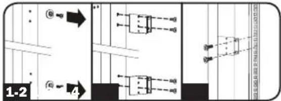
text_image
1-2 4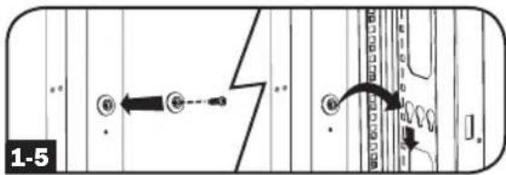
text_image
1-5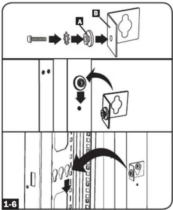
flowchart
graph TD
    A["Receipt"] --> B{Check}
    B --> C["Process Step"]
    C --> D["Product Image"]
    D --> E["Output"]

    subgraph Section 1
        direction LR
        A --> B
        B --> C
        C --> D
        D --> E
    end

    subgraph Section 2
        direction LR
        E --> F["Final Output"]
    end

    G["Device Icon"] --> H["Arrow to Process Step"]
    H --> I["Arrow to Output"]
    style A fill:#f9f,stroke:#333
    style B fill:#ccf,stroke:#333
    style C fill:#cfc,stroke:#333
    style D fill:#fcc,stroke:#333
    style E fill:#cff,stroke:#333
    style F fill:#ffc,stroke:#333
    style G fill:#cfc,stroke:#333
    style H fill:#fcc,stroke:#333
Installation
Connecting the PDU
2-1 Each model is equipped with 1 of 7 different input plugs.


L21-20PL15-30P30P
IEC BOBBred 16A
CS8365C
(3P + N + E)


IEC 309 Blue 60A (3P + E)
IEC 309 Blue 30A (3P + N + E)
| Model Name Input | Plug | Max Input Amps (Limited by Input Cord and Plug) | Input Voltage Range | Output Voltage Range Breakers | Cord Length | Outlets |
| PDU3VN6L2120 L21-20P 16A 208V | 208V and 120V (with 5-15/20R outlets) | N/A | 45 Total: 3 Banks of (2) C19, (12) C13, and 3 Banks of (1) 5-15/20R | |||
| PDU3VN6L2130 L21-30P 24A 208V | 208V and 120V (with 5-15/20R outlets) | 3 x Double Pole, 20A Branch-Rated | 45 Total: 3 Banks of (2) C19, (12) C13, and 3 Banks of (1) 5-15/20R | |||
| PDU3VN6H50B | HUBBLE CS8365C | 35A 200-2 | 40V 200-240V | 3 x Double Pole, 20A Branch-Rated | 48 Total: 3 Banks of (2) C19 and (14) C13 | |
| PDU3VN6G60B | IEC 309 Blue 60A (3P + E) | 35A 200-2 | 40V 200-240V | 3 x Double Pole, 20A Branch-Rated | 48 Total: 3 Banks of (2) C19 and (14) C13 | |
| PDU3XVN6G20 | IEC 309 Red 16A (3P + N + E) | 16A 360-4 | 15V 208-240V N/A | 48 Total: 3 Banks of (2) C19 and (14) C13 | ||
| PDU3VN6G30B | IEC 309 Blue 30A (3P + N + E) | 24A 200-2 | 40V 200-240V | 3 x Double Pole, 20A Branch-Rated | 48 Total: 3 Banks of (2) C19 and (14) C13 | |
| PDU3VN6L2130B L21-30P 24A 200-2 | 40V 200-240V | 3 x Double Pole, 20A Branch-Rated | 48 Total: 3 Banks of (2) C19 and (14) C13 | |||
| PDU3VN6L1530B L15-30P 24A 200-2 | 40V 200-240V | 3 x Double Pole, 20A Branch-Rated | 48 Total: 3 Banks of (2) C19 and (14) C13 | |||
| PDU3VN10L1530B L15-30P 24A 200-2 | 240V 200-240V | 3 x Double Pole, 20A Branch-Rated | 48 Total: 3 Banks of (2) C19 and (14) C13 | |||
| PDU3VN6G60C | IEC 309 Blue 60A (3P + E) | 45A 200-2 | 40V 200-240V | 6 x Double Pole, 20A Branch-Rated | 36 Total: 6 Banks of (6) C13 |
Installation

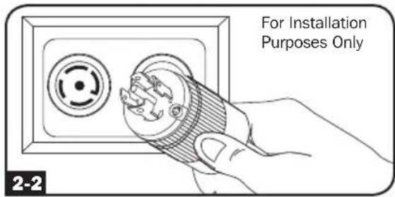
Connect the input plug to your facility's compatible AC power source.
text_image
For Installation Purposes Only 2-2
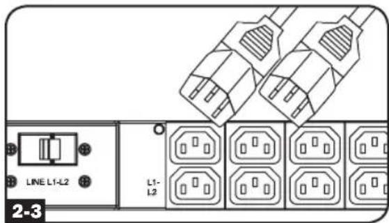
Connect your equipment's input plugs to the appropriate outlets on the PDU. The LED near each bank illuminates when the bank is ready to distribute live AC power.
Note: It is recommended that you do not connect a live load to the PDU. If the load you intend to connect has an ON/OFF switch, please turn the switch to OFF prior to connection.
text_image
LINE L1-L2 L1- L2 2-3
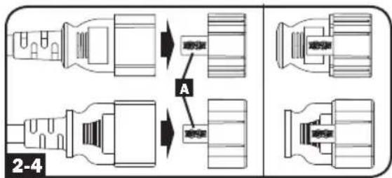
Optional Cord Retention Procedure
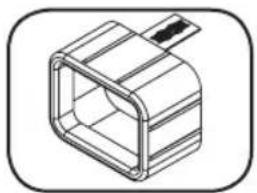
Use the included C14 and C20 plastic sleeves to secure plugs to receptacles. Attach the sleeve to the plug, making sure that the pull tabs A remain outside the plug and that the fit is secure. To unplug equipment properly, use the pull tabs to remove the plug and sleeve from the receptacle.
text_image
A 2-4Networking the PDU
Your PDU can receive IP address assignments via DHCP server (dynamic) or static (manual) addressing methods. See the SNMPWEBCARD installation guide for an explanation of these methods. You can find the guide by going to www.tripplite.com/support and typing "SNMPWEBCARD" in the search field. If you are uncertain which method to use, contact your network administrator for assistance before continuing the configuration process.
Note: The MAC address of the PDU (12-digit string in this format: 000667xxxxx) is printed on a label attached to the PDU enclosure. For static IP address assignments, use the RJ-45 to DB9 configuration cable (part number 73-1243) included with the PDU.
Digital Display
text_image
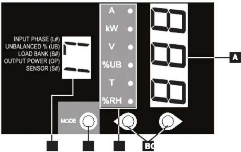
INPUT PHASE (L#) UNBALANCED % (UB) LOAD BANK (B#) OUTPUT POWER (OP) SENSOR (S#) MODE A kW V %UB T %RH BC AA 3-Digit Display: Shows measured or calculated values such as Amperage, Kilowatts, Voltage, Power Unbalance Percentage, Temperature and Humidity.
B Arrow Buttons: Scroll through indicated Input, Bank, Power, Load Balance, Sensor and Display Brightness options using these buttons. A long press of the up or down arrow buttons allows the user to skip to the next sequential measurement category.
C Mode Button: When a menu option is selected using the Arrow Buttons, the Mode Button scrolls through the sub-options within each category. Sub-options are shown by the Indicator LEDs.
D Indicator LEDs: Lit LED indicates which value is being displayed on the 3-digit screen.
Amps (A): When selected, the load on the selected Input Phase (L#) or Load Bank (B#) is displayed in amps.
Wattage (kW): When selected, the load on the selected Load Bank (B#) or Total Output Power (OP) is displayed in kW.
Voltage (V): Input Phase (L#) or Load Bank (B#) voltage is displayed.
Unbalanced Load (%UB): When lit, the display shows the unbalanced load percentage deviance from the average measured value. A value that is zero or closest to zero is desirable.
Temperature (T): If Tripp Lite ENVIROSENSE is connected, the ambient temperature will be displayed when this option is selected. The temperature is displayed in Celsius by default, but can be switched to Fahrenheit.
Relative Humidity (%RH): If Tripp Lite ENVIROSENSE is connected, the relative humidity percentage will be displayed when this option is selected.
E 2-Digit Display: This display indicates which Input Phase (L#), Load Unbalance (UB), Load Bank (B#), Output Power (OP) or Sensor (S#) option is selected.
Digital Display
Button Response Definitions:
| Configuration^1 | Switch | Action | Control Function |
| Standard | Up Pushbutton | Depress 1/2 sec | Sequentially, moves up one selection in the menu. |
| Depress 3 sec | Advances up to the next measurement category. | ||
| Down Pushbutton | Depress 1/2 sec | Sequentially, moves down one selection in the menu. | |
| Depress 3 sec | Advances down to the next measurement category. | ||
| Mode Pushbutton | Depress 1/2 sec | Displays available options for a given measurement category. | |
| Depress 3 sec | Selects the chosen available option for a given configuration category. | ||
| Alternate | Up Pushbutton | Depress 1/2 sec | Sequentially, moves down one selection in the menu. |
| Depress 3 sec | Advances down to the next measurement category. | ||
| Down Pushbutton | Depress 1/2 sec | Sequentially, moves up one selection in the menu. | |
| Depress 3 sec | Advances up to the next measurement category. | ||
| Mode Pushbutton | Depress 1/2 sec | Displays available options for a given measurement category. | |
| Depress 3 sec | Selects the chosen available option for a given configuration category. |
1 Configured via Configuration Category item "Outlet Indicator LED Color Code Options".
Load Bank Receptacle Location and Display References
text_image
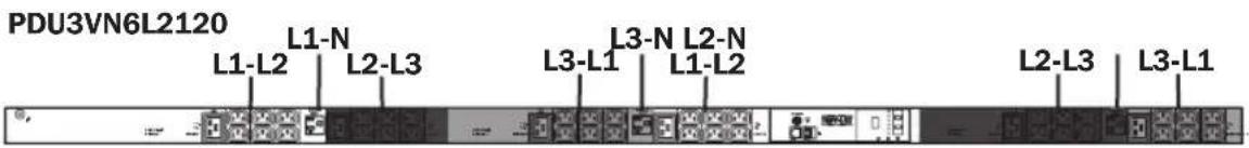
PDU3VN6L2120 L1-L2 L1-N L2-L3 L3-L1 L3-N L2-N L1-L2 L2-L3 L3-L1
text_image
PDU3VN6L2130 L1-L2 L1-N L3-N L2-N L2-L3 L3-L1 L1-L2 L2-L3 L3-L1| MODELS | SILKSCREEN LABEL DESCRIPTION | 2-DIGIT DISPLAY REFERENCE |
| PDU3VN6L2120 | L1-L2 | B1 |
| PDU3VN6L2130 | L2-L3 | B2 |
| L3-L1 | B3 | |
| L1-N (Bank 4) | B4 | |
| L3-N (Bank 5) | B5 | |
| L2-N (Bank 6) | B6 |
Digital Display
PDU3VN6L1530B/PDU3VN10L1530B/PDU3VN6L2130B/PDU3VN6G30B/PDU3VN6H50B/PDU3VN6G60B

text_image
L1-L2 L2-L3 L2-L3 L3-L1 L1-L2 L3-L1| MODELS | SILKSCREEN LABEL DESCRIPTION | 2-DIGIT DISPLAY REFERENCE |
| PDU3VN6L1530B | L1-L2 (Bank 1) | B1 |
| PDU3VN10L1530B | L2-L3 (Bank 2) | B2 |
| PDU3VN6L2130B | ||
| PDU3VN6G30B | L3-L1 (Bank 3) | B3 |
| PDU3VN6H50B | ||
| PDU3VN6G60B |
PDU3XVN6G20

text_image
L1-N L1-NL2-N L2-N L3-N L3-N| MODELS | SILKSCREEN LABEL DESCRIPTION | 2-DIGIT DISPLAY REFERENCE |
| PDU3XVN6G20 | L1-N (Bank 1) | L1 |
| L2-N (Bank 2) | L2 | |
| L3-N (Bank 3) | L3 |
PDU3VN6G60C

text_image
L1-L2 L3-L3 L2-L3L1-L2 L3-L1| MODELS | SILKSCREEN LABEL DESCRIPTION | 2-DIGIT DISPLAY REFERENCE |
| PDU3VN6G60C | L1-L2 (Bank 1) | B1 |
| L2-L3 (Bank 2) | B2 | |
| L3-L1 (Bank 3) | B3 | |
| L1-L2 (Bank 4) | B4 | |
| L2-L3 (Bank 5) | B5 | |
| L3-L1 (Bank 6) | B6 |
INPUT PHASE REFERENCE (FOR ALL 208V MODELS)
| INPUT PHASE REPORTED | 2-DIGIT DISPLAY REFERENCE |
| L1 – L2 | L1 |
| L2 – L3 | L2 |
| L3 – L1 | L3 |
INPUT PHASE REFERENCE (FOR ALL 400V MODELS)
| INPUT PHASE REPORTED | 2-DIGIT DISPLAY REFERENCE |
| L1-N | L1 |
| L2-N | L2 |
| L3-N | L3 |
Using the Digital Display
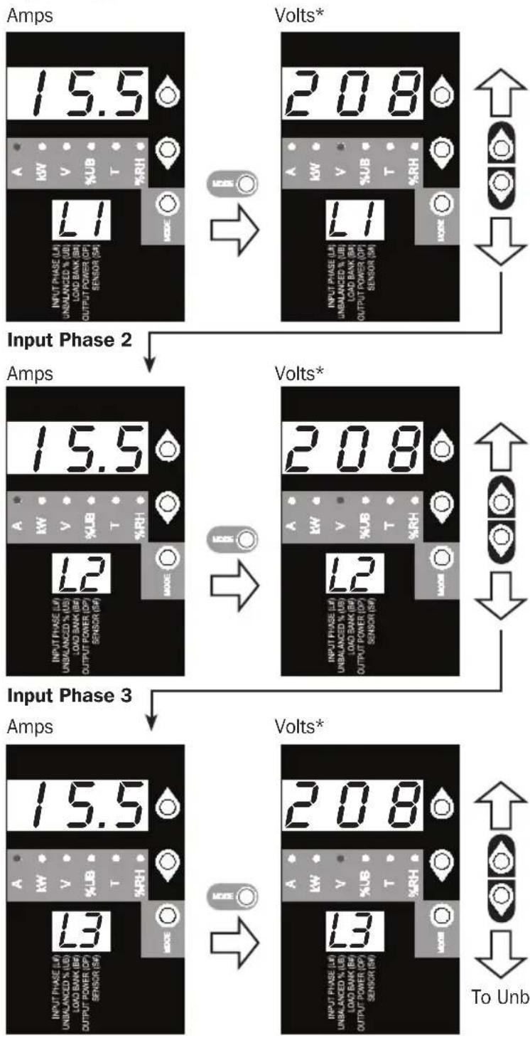
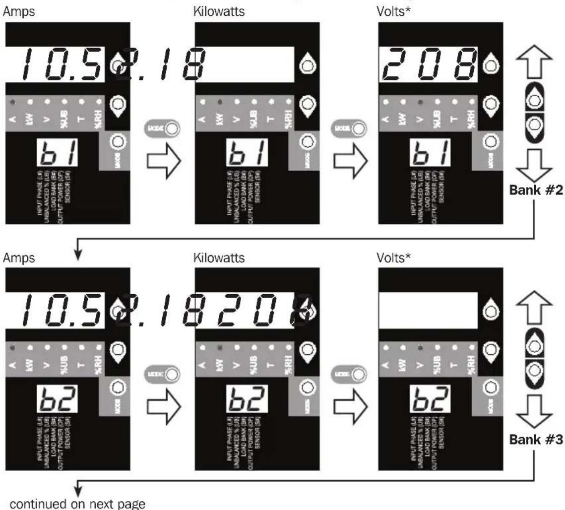
Scrolling Through Input Phases and Options (Measurement Category)
Press Mode button to toggle between options and data within a menu. A momentary press of the arrow buttons switches between menus. A long press skips between measurement categories. The scrolling pattern of the display is outlined below. Note: Three dashes will be shown in the 3-digit display when the input phase voltage is unknown, due to abnormal tripped breaker conditions.
Input Phase 1
flowchart
graph TD
    A["Input Phase 2"] --> B["Amps: 15.5 kW UNBLANZED % (UB) LOAD BANK (BH OUTPUT POWER (OP) SENSOR (SH)"]
    B --> C["Volts*: 208 kW UNBLANZED % (UB) LOAD BANK (BH OUTPUT POWER (OP) SENSOR (SH)"]
    C --> D["Output to Unba"]

    E["Input Phase 3"] --> F["Amps: 15.5 kW UNBLANZED % (UB) LOAD BANK (BH OUTPUT POWER (OP) SENSOR (SH)"]
    F --> G["Volts*: 208 kW UNBLANZED % (UB) LOAD BANK (BH OUTPUT POWER (OP) SENSOR (SH)"]
    G --> H["Output to Unba"]

    I["Input Phase 2"] --> J["Volts*: 208 kW UNBLANZED % (UB) LOAD BANK (BH OUTPUT POWER (OP) SENSOR (SH)"]
    J --> K["Volts*: 208 kW UNBLANZED % (UB) LOAD BANK (BH OUTPUT POWER (OP) SENSOR (SH)"]
    K --> L["Output to Unba"]

    M["Input Phase 3"] --> N["Volts*: 208 kW UNBLANZED % (UB) LOAD BANK (BH OUTPUT POWER (OP) SENSOR (SH)"]
    N --> O["Volts*: 208 kW UNBLANZED % (UB) LOAD BANK (BH OUTPUT POWER (OP) SENSOR (SH)"]
    O --> P["Output to Unba"]

    Q["Input Phase 3"] --> R["Volts*: 208 kW UNBLANZED % (UB) LOAD BANK (BH OUTPUT POWER (OP) SENSOR (SH)"]
    R --> S["Volts*: 208 kW UNBLANZED % (UB) LOAD BANK (BH OUTPUT POWER (OP) SENSOR (SH)"]
    S --> T["Output to Unba"]
* Note: Voltages displayed are phase-to-phase voltages (i.e., L1 display will indicate L1-L2 voltage). Select models display phase-to-neutral voltages.
Using the Digital Display
Press Mode button to toggle between options and data within a menu. A momentary press of the arrow buttons switches between menus. A long press skips between measurement categories. The scrolling pattern of the display is outlined below.
Unbalanced Load Detect (Measurement Category)
Phase Imbalance %

text_image
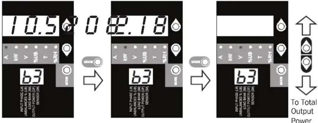
2.0 INPUT PHASE (UE) UNSLANCED % (UE) LOAD BANK (RW) OUTPUT POWER OF SENSOR (SB) U6 A BW V %US T %RH MAX ↑ ↓Scrolling Through Load Banks and Options (Measurement Category)
Scroll through the parameter display for each Load Bank using Mode and ↓buttons.
*Note: For 208V models, voltages displayed are phase-to-phase voltages (i.e., b1 display will indicate L1-L2 voltage). Select models display phase-to-neutral voltages.
flowchart
graph TD
    A["Amps"] --> B["Kilowatts"]
    B --> C["Volts*"]
    C --> D["Bank #2"]
    D --> E["Amps"]
    E --> F["Kilowatts"]
    F --> G["Volts*"]
    G --> H["Bank #3"]
    H --> I["continued on next page"]
Using the Digital Display
Amps Kilowatts Volts*
text_image
10.5 0 82.18 INPUT PHASE LA UNALANCED % UB LOAD BANK SB OUTPUT POWER OP SENSOR SB 63 INPUT PHASE LA UNALANCED % UB LOAD BANK SB OUTPUT POWER OP SENSOR SB 63 INPUT PHASE LA UNALANCED % UB LOAD BANK SB OUTPUT POWER OP SENSOR SB 63 To Total Output PowerNote: Continue for Load Banks
4-6 for models PDU3VN6G60C,
PDU3VN6L2120 and
PDU3VN6L2130.
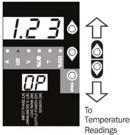
Press Mode button to toggle between options and data within a menu. A momentary press of the arrow buttons switches between menus. A long press skips between measurement categories. The scrolling pattern of the display is outlined below.
Total Output Power (Measurement Category)
Kilowatts
text_image
1.23 MW V %JB T %RH OP INPUT PHASE (L) UNBALANCED % UB LOAD BANK (R) OUTPUT POWER (OP) SENSOR (R) MOS To Temperature ReadingsUsing the Digital Display
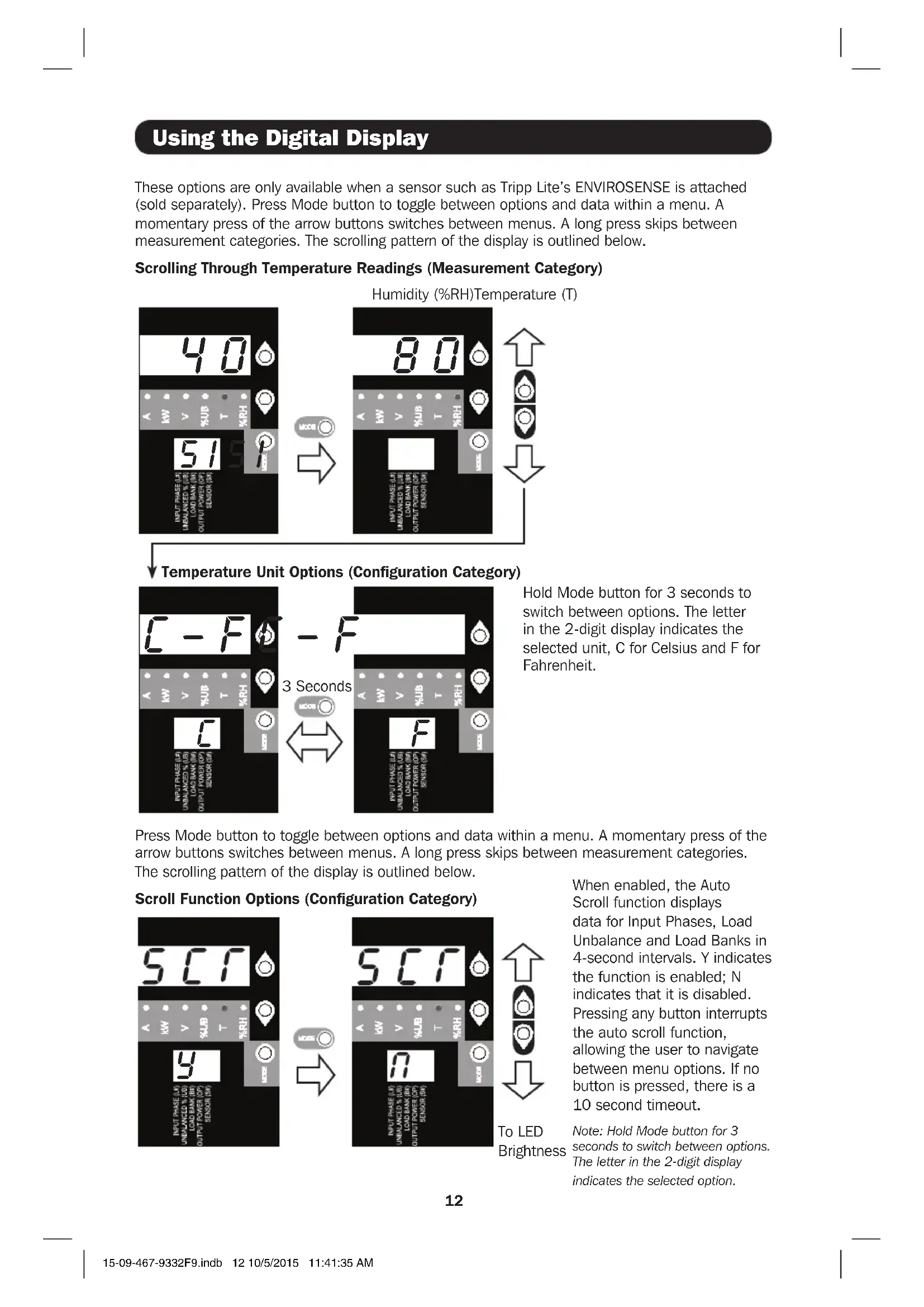
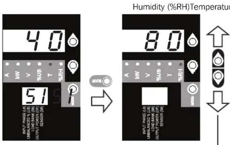
These options are only available when a sensor such as Tripp Lite's ENVIROSENSE is attached (sold separately). Press Mode button to toggle between options and data within a menu. A momentary press of the arrow buttons switches between menus. A long press skips between measurement categories. The scrolling pattern of the display is outlined below.
Scrolling Through Temperature Readings (Measurement Category)
text_image
Humidity (%RH)Temperature 40 51 INPUT PHASE (L) UNBALANCED % LIB LOAD BANK (R) OUTPUT POWER (P) SENSOR (R) UCCB 80 INPUT PHASE (L) UNBALANCED % LIB LOAD BANK (R) OUTPUT POWER (P) SENSOR (R)Temperature Unit Options (Configuration Category)
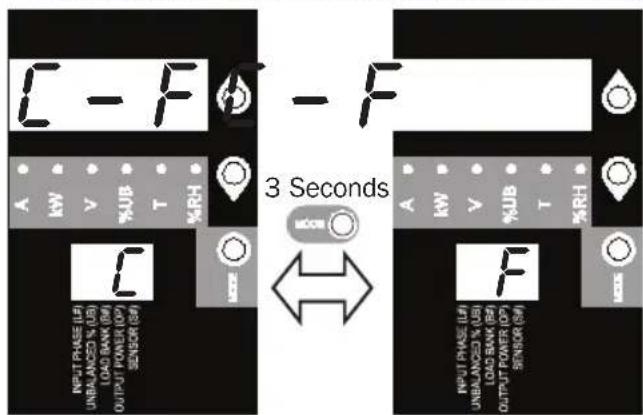
text_image
C - F - F A kW V %JB T %RH 3 Seconds ← A kW V %JB T %RH F INPUT PHASE (U) UNBALANCED % (U) LOAD BANK (U) OUTPUT POWER (OP) SENSOR (SB) OUTPUT POWER (OP) SENSOR (SB)Hold Mode button for 3 seconds to switch between options. The letter in the 2-digit display indicates the selected unit, C for Celsius and F for Fahrenheit.
Press Mode button to toggle between options and data within a menu. A momentary press of the arrow buttons switches between menus. A long press skips between measurement categories. The scrolling pattern of the display is outlined below.
Scroll Function Options (Configuration Category)
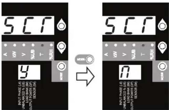
text_image
SC1 A kW V %LB T %RH 9 INPUT PHASE (W) UNBALANCED % (U) LOAD BANK (BW) OUTPUT POWER (CP) SENSOR (SW) MOSER → SC1 A kW V %LB T %RH 9 INPUT PHASE (W) UNBALANCED % (UB) LOAD BANK (BW) OUTPUT POWER (CP) SENSOR (SW) MOSER
To LED
Brightness
When enabled, the Auto Scroll function displays data for Input Phases, Load Unbalance and Load Banks in 4-second intervals. Y indicates the function is enabled; N indicates that it is disabled. Pressing any button interrupts the auto scroll function, allowing the user to navigate between menu options. If no button is pressed, there is a 10 second timeout.
Note: Hold Mode button for 3 seconds to switch between options. The letter in the 2-digit display indicates the selected option.
Using the Digital Display
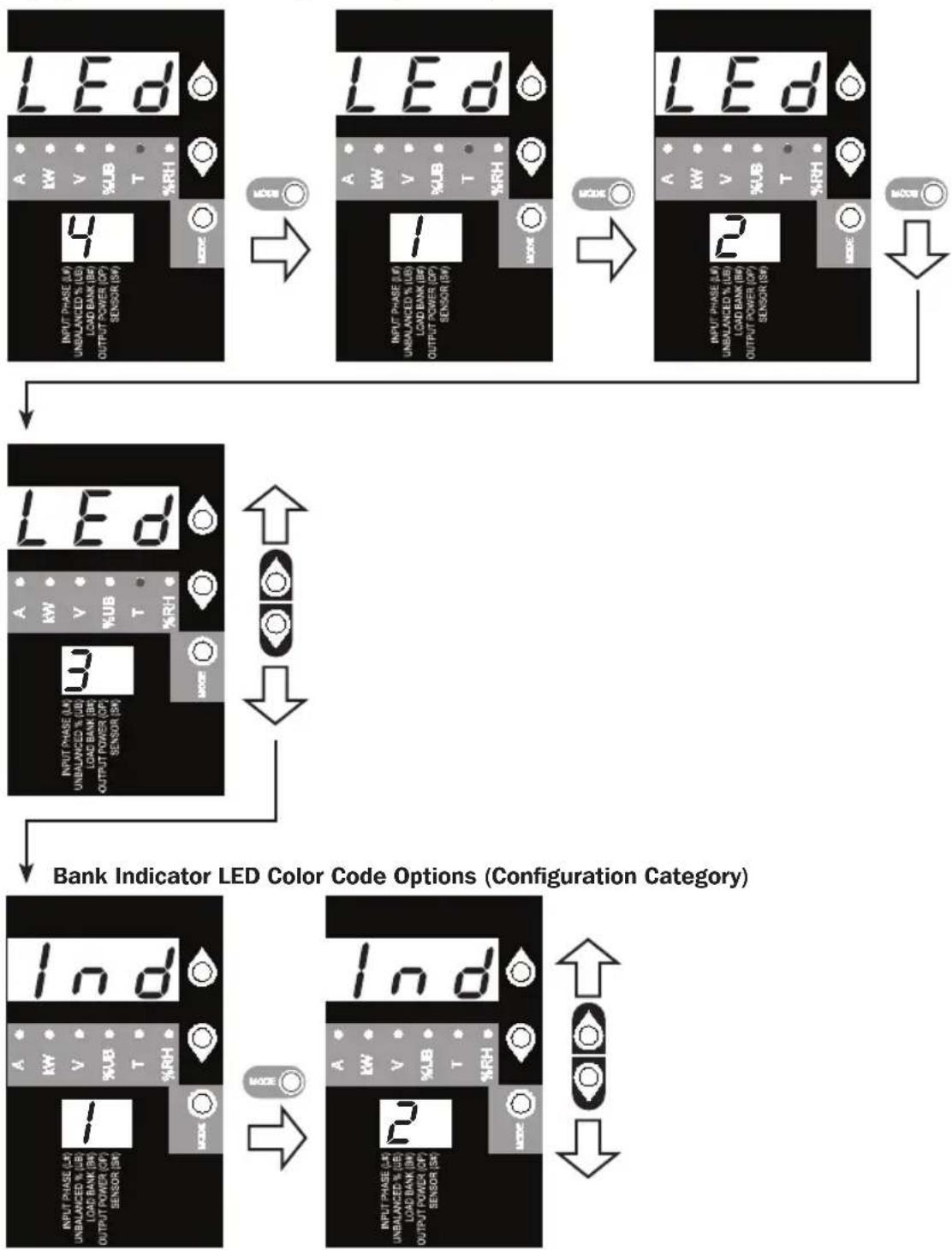
LED Brightness and Color Scheme (Configuration Category)
Hold the Mode button for 3 seconds to scroll through each option. The number in the 2-digit display is defined as: 1=25%; 2=50%; 3=75%; 4=100%
flowchart
graph TD
    A["LED Display"] --> B["Input Phase (A) 4 UNBALANCED % (LB) LOAD BANK (BH) OUTPUT POWER (CP) SENSOR (SW)"]
    B --> C["LED Display"]
    C --> D["Input Phase (A) 1 UNBALANCED % (LB) LOAD BANK (BH) OUTPUT POWER (CP) SENSOR (SW)"]
    D --> E["LED Display"]
    E --> F["Input Phase (A) 2 UNBALANCED % (LB) LOAD BANK (BH) OUTPUT POWER (CP) SENSOR (SW)"]
    F --> G["Output Power (CP) Sensor (SW)"]
    G --> H["LED Display"]
    H --> I["Output Power (CP) Sensor (SW)"]
    I --> J["Output Power (CP) Sensor (SW)"]
    J --> K["Output Power (CP) Sensor (SW)"]
    K --> L["Output Power (CP) Sensor (SW)"]
    L --> M["Output Power (CP) Sensor (SW)"]
    M --> N["Output Power (CP) Sensor (SW)"]
    N --> O["Output Power (CP) Sensor (SW)"]
    O --> P["Output Power (CP) Sensor (SW)"]
    P --> Q["Output Power (CP) Sensor (SW)"]
    Q --> R["Output Power (CP) Sensor (SW)"]
    R --> S["Output Power (CP) Sensor (SW)"]
    S --> T["Output Power (CP) Sensor (SW)"]
    T --> U["Output Power (CP) Sensor (SW)"]
    U --> V["Output Power (CP) Sensor (SW)"]
    V --> W["Output Power (CP) Sensor (SW)"]
    W --> X["Output Power (CP) Sensor (SW)"]
    X --> Y["Output Power (CP) Sensor (SW)"]
    Y --> Z["Output Power (CP) Sensor (SW)"]
    Z --> AA["Output Power (CP) Sensor (SW)"]
    AA --> AB["Output Power (CP) Sensor (SW)"]
    AB --> AC["Output Power (CP) Sensor (SW)"]
    AC --> AD["Output Power (CP) Sensor (SW)"]
    AD --> AE["Output Power (CP) Sensor (SW)"]
    AE --> AF["Output Power (CP) Sensor (SW)"]
    AF --> AG["Output Power (CP) Sensor (SW)"]
    AG --> AH["Output Power (CP) Sensor (SW)"]
    AH --> AI["Output Power (CP) Sensor (SW)"]
    AI --> AJ["Output Power (CP) Sensor (SW)"]
    AJ --> AK["Output Power (CP) Sensor (SW)"]
    AK --> AL["Output Power (CP) Sensor (SW)"]
    AL --> AM["Output Power (CP) Sensor (SW)"]
    AM --> AN["Output Power (CP) Sensor (SW)"]
    AN --> AO["Output Power (CP) Sensor (SW)"]
    AO --> AP["Output Power (CP) Sensor (SW)"]
    AP --> AQ["Output Power (CP) Sensor (SW)"]
    AQ --> AR["Output Power (CP) Sensor (SW)"]
    AR --> AS["Output Power (CP) Sensor (SW)"]
    AS --> AT["Output Power (CP) Sensor (SW)"]
    AT --> AU["Output Power (CP) Sensor (SW)"]
    AU --> AV["Output Power (CP) Sensor (SW)"]
    AV --> AW["Output Power (CP) Sensor (SW)"]
    AW --> AX["Output Power (CP) Sensor (SW)"]
    AX --> AY["Output Power (CP) Sensor (SW)"]
    AY --> AZ["Output Power (CP) Sensor (SW)"]
    AZ --> BA["Output Power (CP) Sensor (SW)"]
    BA --> BB["Output Power (CP) Sensor (SW)"]
    BB --> BC["Output Power (CP) Sensor (SW)"]
    BC --> BD["Output Power (CP) Sensor (SW)"]
    BD --> BE["Output Power (CP) Sensor (SW)"]
    BE --> BF["Output Power (CP) Sensor (SW)"]
    BF --> BG["Output Power (CP) Sensor (SW)"]
    BG --> BH["Output Power (CP) Sensor (SW)"]
    BH --> BI["Output Power (CP) Sensor (SW)"]
    BI --> BJ["Output Power (CP) Sensor (SW)"]
    BJ --> BK["Output Power (CP) Sensor (SW)"]
    BK --> BL["Output Power (CP) Sensor (SW)"]
    BL --> BM["Output Power (CP) Sensor (SW)"]
    BM --> BN["Output Power (CP) Sensor (SW)"]
    BN --> BO["Output Power (CP) Sensor (SW)"]
    BO --> BP["Output Power (CP) Sensor (SW)"]
    BP --> BQ["Output Power (CP) Sensor (SW)"]
    BQ --> BR["Output Power (CP) Sensor (SW)"]
    BR --> BS["Output Power (CP) Sensor (SW)"]
    BS --> BT["Output Power (CP) Sensor (SW)"]
    BT --> BU["Output Power (CP) Sensor (SW)"]
    BU --> BV["Output Power (CP) Sensor (SW)"]
    BV --> BW["Output Power (CP) Sensor (SW)"]
Hold the Mode button for 3 seconds to switch between options. The number in the 2-digit display indicates the selected scheme. 1=Standard, 2=Alternate
Using the Digital Display
BANK INDICATOR LED DEFINITIONS:
| LED Configuration | LED Color Outlet Status Description | |
| Standard^1 | Off Off Bank power is absent | |
| Green On Circuit breaker is on – Bank power is present | ||
| Yellow On | ||
| Red Off | ||
| Red Flashing Off Circuit breaker has tripped – Bank power is absent | ||
| Alternate | Off Off Bank power is absent | |
| Red On Circuit breaker is on – Bank power is present | ||
| Red Flashing On | ||
| Green Off Bank is disabled – Bank power is absent | ||
| Green Flashing Off Circuit breaker has tripped – Bank power is absent | ||
^1 This is the default configuration.
Display Options
LED Test
Hold the Mode button for 3 seconds to test the display. For 5 seconds, all LEDs and display segments will light green, while all Load Indicator LEDs will light yellow. Please visit www.tripplite.com/support for issues with display segment or Indicator LED functionality.


Viewing the IP Address

At any point, pressing both of the arrow buttons simultaneously for 1/2 second displays the unit's IP address in the 2-digit display.

Rotating the Display


At any point, pressing both of the arrow buttons simultaneously and holding for 3 seconds rotates the 2-digit and 3-digit displays.


Features
natural_image
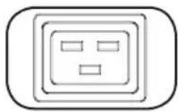
Simple line drawing of an electrical outlet with three slots (no text or symbols)C13 C19
natural_image
Simple line drawing of an electrical outlet with three slots and two connectors, enclosed in a rounded square frame (no text or symbols)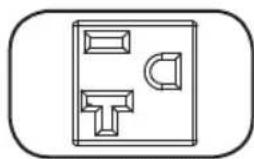
natural_image
Simple line drawing of a door with handle and seat (no text or symbols)NEMA 5-15/20R
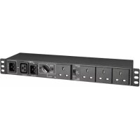
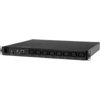
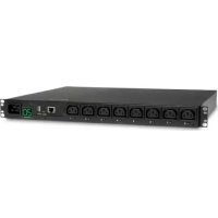
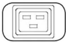
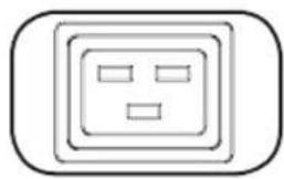
Outlets: During normal operation, the outlets distribute AC power to connected equipment.
Note: PDU3VN6G60C does not include C19 receptacles.
Note: NEMA 5-15/20R receptacles are only included with the PDU3VN6L2120/PDU3VN6L2130 models.
natural_image
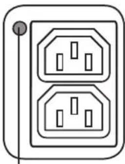
Simple line drawing of two electrical socket sockets with a power outlet (no text or symbols)Bank Status LED
Bank Status LED: Once the unit is powered on, each Bank Status LED will illuminate when the associated bank is ready to distribute live AC power.
| LED Color LED Status Comments/Notes | ||
| Green On Normal operation. | ||
| Yellow On Bank's current has exceeded 80% of its current rating. | ||
| Red Off Bank's voltage is below the Low Voltage threshold. | ||
| Flashing Red Off Circuit breaker for this bank has tripped. | ||
| Off Off Bank is powered off. | ||
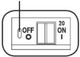
Push-to-Reset Guard
text_image
OFF 20 ON INote: Colors noted here reflect standard LED configuration. See chart on page 14 for full LED color definitions.
Circuit Breaker (Select Models): Each Load Bank is protected by a circuit breaker. If the connected equipment load exceeds the Maximum Load Rating for those banks of the PDU, the circuit breaker will trip. Disconnect excess load and reset the breaker.
Note: Each breaker comes equipped with a push-to-reset guard to prevent accidental breaker tripping. To turn off the breaker, insert a flathead screwdriver into the reset slot.
Note: PDU3VN6L2120 and PDU3XVN6G20 do not include breakers.
Mounting Brackets: Use these brackets as an alternate PDU mounting method.
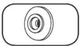
Mounting Buttons: Come pre-installed on the back side of the PDU and are used for toolless mounting. Note: Four additional mounting buttons are included for alternate rack styles.
natural_image
Simple line drawing of a door with a handle and screw, enclosed in a rounded rectangle (no text or symbols)PDUMVROTATEBRKT Mounting Accessory: Use these V-shaped brackets to mount the PDU with its outlets facing the rear of the rack.
Features
natural_image
Technical line drawing of a mechanical component with no visible text or symbolsC14 Plug Sleeve: (Optional) Use the included C14 plastic sleeves to secure plugs to receptacles. Attach the sleeve to the plug making sure that the pull tabs remain outside the plug and that the fit is secure. To unplug equipment properly, use the pull tabs to remove the plug and sleeve from the receptacle.
natural_image
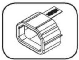
Isometric line drawing of a rectangular mechanical component with a protruding rod (no text or symbols)C20 Plug Sleeve: (Optional) Use the included C20 plastic sleeves to secure plugs to receptacles. Attach the sleeve to the plug making sure that the pull tabs remain outside the plug and that the fit is secure. To unplug equipment properly, use the pull tabs to remove the plug and sleeve from the receptacle.

Ground Screw: Use this to connect any equipment that requires a chassis ground.

text_image
RESETSNMP Reset Button: Press the reset button for 3 seconds to reboot the PDU's network card. Rebooting the network card will not erase network settings or interrupt AC power. The reset button is recessed. Use a paper clip or other suitable object to press it.

natural_image
Simple diagram of a circular connector or socket with dot pattern inside a square frame (no text or symbols)PS/2 Port: Use this port to connect a Tripp Lite ENVIROSENSE environmental sensor to provide remote temperature/humidity monitoring and a dry contact interface to control and monitor alarm, security and telecom devices. Visit www.triplite.com for ordering information.
Note: Do not connect a keyboard or mouse to this port.
natural_image
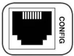
Black and white icon of a Ethernet ports with 'CONFIG' text on the side (no additional symbols or text)RJ-45 Configuration Port: Use this port to provide a direct terminal connection to a computer with a terminal emulation program. An RJ-45 to DB9 cable (part number 73-1243) is included with the PDU. If you need a replacement cable, visit www.tripplite.com for ordering information.
Note: Configuration options can found in the SNMPWEBCARD installation guide. You can find the guide by going to www.tripplite.com/support and typing "SNMPWEBCARD" in the search field.
text_image
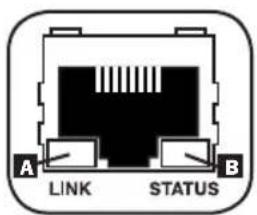
A LINK STATUS BEthernet Port: Use this RJ-45 jack to connect the PDU to the network with a standard Ethernet patch cable. The Link LED A and Status LED B indicate several operating conditions, as shown in the table below. This port is not compatible with PoE (Power Over Ethernet) applications.
| Network Operating Conditions | |
| A Link LED Color | |
| Off No Network Connection | |
| Flashing Amber 100 Mbps Network Connection | |
| Flashing Green 10 Mbps Network Connection | |
| B Status LED Color | |
| Off Card Not Initialized | |
| Steady or Flashing Green Card Initialized and Operational | |
| Steady Amber Error - Card Not Initialized | |
Configuration and Operation
Remote Monitoring
The PDU provides remote monitoring and more via Web browser, telnet and SNMP-based Network Management Systems. For more information about configuration and operation of the PDU via the PowerAlert Web browser interface, refer to the SNMPWEBCARD User's Guide. You can find the guide by going to www.tripplite.com/support and typing "SNMPWEBCARD" in the search field.
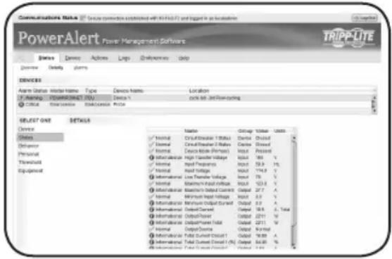
text_image
Communications Note Source: connection established with 10.0% or logged in the location PowerAlert Power Management Software TRIPP-LITE Device Device Actions Loop Preferences Data Device Details Plums DRIVERS Name: Device Name Type Device Name Location U:\Design\Suppression\DSU Device % drive set-2#Recoycling Critical Transaction Transaction Price SELECT NAME DETAILS Device Status Device Name Type Device Name Location U:\Design\Suppression\DSU Device % drive set-2#Recoycling Critical Transaction Transaction Price Device Name Device Name Device Name Device Name Device Name Device Name Device Name Device Name Device Name Device Name Device Name Device Name Device Name Device Name Device Name Device Name Device Name Device Name Device Name Device Name Device Name Device Name Device Name Device Name Device Name Device Name Device Name Device Name Device Name Device Name Device Name Device Name Device Name Device Name: Device Name: Device Name: Device Name: Device Name: Device Name: Device Name: Device Name: Device Name: Device Name: Device Name: Device Name: Device Name: Device Name: Device Name: Device Name: Device Name: Device Name: Device Name: Device Name: Device Name: Device Name: Device Name: Device Name: Device Name: Device Name: Device Name: Device Name: Device Name: Device Name: Device Name: Device Name: Device Name: Device Name: device name: device name: device name: device name: device name: device name: device name: device name: device name: device name: device name: device name: device name: device name: device name: device name: device name: device name: device name: device name: device name: device name: device name: device name: device name: device name: device name: device name: device name: device name: device name: device name: device name: device name: device name: device name: device name: device name: device name: device name: device name: device name: device name: device name: device name: device name: device name: device name: device name: device name: device name: device name: device name: device name: device name: device name: device name: device name: device name: device name: device name: device time: 10:00:00:00:00:00:00:00:00:00:00:00:00:00:00:00:00:00:00:00:00:00:00:00:00:00:00:00:00:00:00:00:00:00:05:15:15:15:15:15:15:15:15:15:15:15:15:15:15:15:15:15:15:15:15:15:15:15:15:15:15:15:15:15:15:15:15:15:16:38:38:38:38:38:38:38:38:38:38:38:38:38:38:38:38:38:38:38:38:38:38:38:38:38:38:38:38:38:38:38:38:38:38 : 76 : 92 : 94 : 96 : 98 : 100 : 102 : 104 : 106 : 108 : 110 : 112 : 114 : 116 : 118 : 120 : 122 : 124 : 126 : 128 : 130 : 132 : 134 : 136 : 138 : 140 : 142 : 144 : 146 : 148 : 150 : 152 : 154 : 156 : 158 : 160 : 162 : 164 : 166 : 168 : 170 : 172 : 174 : 176 : 178 : 180 : 182 : 184 : 186 : 188 : 190 : 192 : 194 : 196 : 198 : 200 : 202 : 204 : 206 : 208 : 210 : 212 : 214 : 216 : 218 : 220 : 222 : 224 : 226 : 228 : 230 : 232 : 234 : 236 : 238 : 240 : 242 : 244 : 246 : 248 : 250 : 252 : 254 : 256 : 258 : 260 : 262 : 264 : 266 : 268 : 270 : 272 : 274 : 276 : 278 : 280 : 282 : 284 : 286 : 288 : 290 : 292 : 294 : 296 : 298 : 300 : 302 : 304 : 306 : 308 : 310 : 312 : 314 : 316 : 318 : 320 : 322 : 324 : Normal Circuitable / Total (bit) Circuitable / Total (bit) Circuitable / Total (bit) Circuitable / Total (bit) Circuitable / Total (bit) Circuitable / Total (bit) Circuitable / Total (bit) Circuitable / Total (bit) Circuitable / Total (bit) Circuitable / Total (bit) Circuitable / Total (bit) Circuitable / Total (bit) Circuitable / Total (bit) Circuitable/Total (bit) Circuitable/Total (bit) Circuitable/Total (bit) Circuitable/Total (bit) Circuitable/Total (bit) Circuitable/Total (bit) Circuitable/Total (bit) Circuitable/Total (bit) Circuitable/Total (bit) Circuitable/Total (bit) Circuitable/Total (bit) Circuitable/Total (bit) Circuitable/Total (bit) Dialysis/Total (bit) Dialysis/Total (bit) Dialysis/Total (bit) Dialysis/Total (bit) Dialysis/Total (bit) Dialysis/Total (bit) Dialysis/Total (bit) Dialysis/Total (bit) Dialysis/Total (bit) Dialysis/Total (bit) Dialysis/Total (bit) Dialysis/Total (bit) Dialysis/Total (Bit) Dialysis/Total (Bit) Dialysis/Total (Bit) Dialysis/Total (Bit) Dialysis/Total (Bit) Dialysis/Total (Bit) Dialysis/Total (Bit) Dialysis/Total (Bit) Dialysis/Total (Bit) Dialysis/Total (Bit) Dialysis/Total (Bit) Dialysis/Total (Bit) Dialysis/Total (Bit) Dialyside/Total (Bit) Dialysis/Total (Bit) Dialysis/Total (Bit) Dialysis/Total (Bit) Dialysis/Total (Bit) Dialysis/Total (Bit) Dialysis/Total (Bit) Dialysis/Total (Bit) Dialysis/Total (Bit) Dialysis/Total (Bit) Dialysis/Total (Bit) Dialysis/Total (Bit) Dialysis/Total ( bit ) Dialysis/Total ( bit ) Dialysis/Total ( bit ) Dialysis/Total ( bit ) Dialysis/Total ( bit ) Dialysis/Total ( bit ) Dialysis/Total ( bit ) Dialysis/Total ( bit ) Dialysis/Total ( bit ) Dialysis/Total ( bit ) Dialysis/Total ( bit ) Dialysis/Total ( bit ) Dialysis/Total ( bit ) Dialysis / Total Dialysis / Total Dialysis / Total Dialysis / Total Dialysis / Total Dialysis / Total Dialysis / Total Dialysis / Total Dialysis / Total Dialysis / Total Dialysis / Total Dialysis / Total Dialysis / Total Dialysis / Total Dialysis / Total Dialysis / Total Dialysis / Total Dialysis / Total Dialysis / Total Dialysis / Total Dialysis / TotalService
Your Tripp Lite product is covered by the warranty described in this manual. A variety of Extended Warranty and On-Site Service Programs are also available from Tripp Lite. For more information on service, visit www.triplite.com/support. Before returning your product for service, follow these steps:
- Review the installation and operation procedures in this manual to ensure that the service problem does not originate from a misreading of the instructions.
- If the problem continues, do not contact or return the product to the dealer. Instead, visit www.tripplite.com/support.
- If the problem requires service, visit www.triplite.com/support and click the Product Returns link. From here you can request a Returned Material Authorization (RMA) number, which is required for service. This simple on-line form will ask for your unit's model and serial numbers, along with other general purchaser information. The RMA number, along with shipping instructions will be emailed to you. Any damages (direct, indirect, special or consequential) to the product incurred during shipment to Tripp Lite or an authorized Tripp Lite service center is not covered under warranty. Products shipped to Tripp Lite or an authorized Tripp Lite service center must have transportation charges prepaid. Mark the RMA number on the outside of the package. If the product is within its warranty period, enclose a copy of your sales receipt. Return the product for service using an insured carrier to the address given to you when you request the RMA.
Warranty and Product Registration
2- YEAR LIMITED WARRANTY
Seller warrants this product, if used in accordance with all applicable instructions, to be free from original defects in material and workmanship for a period of 2 years from the date of initial purchase. If the product should prove defective in material or workmanship within that period, Seller will repair or replace the product, in its sole discretion. Service under this Warranty can only be obtained by your delivering or shipping the product (with all shipping or delivery charges prepaid) to: Tripp Lite, 1111 W. 35th Street, Chicago, IL 60609 USA. Seller will pay return shipping charges. Visit www.triplite.com/support before sending any equipment back for repair.
THIS WARRANTY DOES NOT APPLY TO NORMAL WEAR OR TO DAMAGE RESULTING FROM ACCIDENT, MISUSE, ABUSE OR NEGLECT. SELLER MAKES NO EXPRESS WARRANTIES OTHER THAN THE WARRANTY EXPRESSLY SET FORTH HEREIN. EXCEPT TO THE EXTENT PROHIBITED BY APPLICABLE LAW, ALL IMPLIED WARRANTIES, INCLUDING ALL WARRANTIES OF MERCHANTABILITY OR FITNESS, ARE LIMITED IN DURATION TO THE WARRANTY PERIOD SET FORTH ABOVE; AND THIS WARRANTY EXPRESSLY EXCLUDES ALL INCIDENTAL AND CONSEQUENTIAL DAMAGES. (Some states do not allow limitations on how long an implied warranty lasts, and some states do not allow the exclusion or limitation of incidental or consequential damages, so the above limitations or exclusions may not apply to you. This Warranty gives you specific legal rights, and you may have other rights which vary from jurisdiction to jurisdiction).
WARNING: The individual user should take care to determine prior to use whether this device is suitable, adequate or safe for the use intended. Since individual applications are subject to great variation, the manufacturer makes no representation or warranty as to the suitability or fitness of these devices for any specific application.
PRODUCT REGISTRATION
Visit www.tripplite.com/warranty today to register your new Tripp Lite product. You'll be automatically entered into a drawing for a chance to win a FREE Tripp Lite product!*
* No purchase necessary. Void where prohibited. Some restrictions apply. See website for details.
FCC Notice, Class A
This device complies with part 15 of the FCC Rules. Operation is subject to the following two conditions: (1) This device may not cause harmful interference, and (2) this device must accept any interference received, including interference that may cause undesired operation.
Note: This equipment has been tested and found to comply with the limits for a Class A digital device, pursuant to part 15 of the FCC Rules. These limits are designed to provide reasonable protection against harmful interference when the equipment is operated in a commercial environment. This equipment generates, uses, and can radiate radio frequency energy and, if not installed and used in accordance with the instruction manual, may cause harmful interference to radio communications. Operation of this equipment in a residential area is likely to cause harmful interference in which case the user will be required to correct the interference at his own expense. The user must use shielded cables and connectors with this equipment. Any changes or modifications to this equipment not expressly approved by Tripp Lite could void the user's authority to operate this equipment.
Regulatory Compliance Identification Numbers
For the purpose of regulatory compliance certifications and identification, your Tripp Lite product has been assigned a unique series number. The series number can be found on the product nameplate label, along with all required approval markings and information. When requesting compliance information for this product, always refer to the series number. The series number should not be confused with the marking name or model number of the product.
WEEE Compliance Information for Tripp Lite Customers and Recyclers (European Union)

Under the Waste Electrical and Electronic Equipment (WEEE) Directive and implementing regulations, when customers buy new electrical and electronic equipment from Tripp Lite they are entitled to:
- Send old equipment for recycling on a one-for-one, like-for-like basis (this varies depending on the country)
- Send the new equipment back for recycling when this ultimately becomes waste
Tripp Lite has a policy of continuous improvement. Specifications are subject to change without notice.

text_image
TRIPP·LITE
1111 W. 35th Street, Chicago, IL 60609 USA • www.tripplite.com/support
1111 W. 35th Street, Chicago, IL 60609 USA • www.tripplite.com/support
natural_image
Diagram of a server rack with a directional arrow indicating movement, no text or symbols present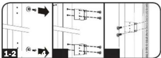
text_image
1-2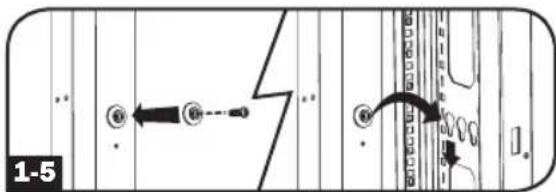
text_image
1-5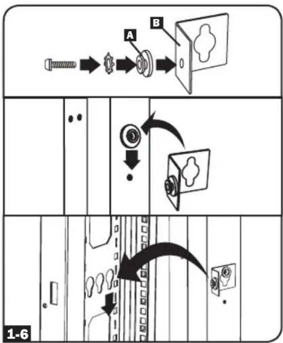
flowchart
graph TD
    A["Start"] --> B["Close"]
    B --> C["Close"]
    C --> D["Lock"]
    D --> E["Door"]
    style A fill:#f9f,stroke:#333
    style E fill:#ccf,stroke:#333
Instalación
Conexión del PDU
text_image
LINE L1-L2 L1- L2 2-3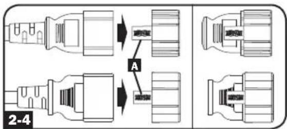
text_image
A 2-4flowchart
graph TD
    A["LED"] --> B["LED"]
    B --> C["LED"]
    C --> D["LED"]
    D --> E["LED"]
    E --> F["INPTH PHASE (A) UNBALANCED % (LB) LOAD BANK (BH) OUTPUT POWER (CP) SENSOR (SW)"]
    F --> G["INPTH PHASE (B) UNBALANCED % (LB) LOAD BANK (BH) OUTPUT POWER (CP) SENSOR (SW)"]
    G --> H["INPTH PHASE (C) UNBALANCED % (LB) LOAD BANK (BH) OUTPUT POWER (CP) SENSOR (SW)"]
    H --> I["INPTH PHASE (D) UNBALANCED % (LB) LOAD BANK (BH) OUTPUT POWER (CP) SENSOR (SW)"]
    I --> J["INPTH PHASE (E) UNBALANCED % (LB) LOAD BANK (BH) OUTPUT POWER (CP) SENSOR (SW)"]
    J --> K["INPTH PHASE (F) UNBALANCED % (LB) LOAD BANK (BH) OUTPUT POWER (CP) SENSOR (SW)"]
    K --> L["INPTH PHASE (G) UNBALANCED % (LB) LOAD BANK (BH) OUTPUT POWER (CP) SENSOR (SW)"]
    L --> M["INPTH PHASE (H) UNBALANCED % (LB) LOAD BANK (BH) OUTPUT POWER (CP) SENSOR (SW)"]
    M --> N["INPTH PHASE (I) UNBALANCED % (LB) LOAD BANK (BH) OUTPUT POWER (CP) SENSOR (SW)"]
    N --> O["INPTH PHASE (J) UNBALANCED % (LB) LOAD BANK (BH) OUTPUT POWER (CP) SENSOR (SW)"]
    O --> P["INPTH PHASE (K) UNBALANCED % (LB) LOAD BANK (BH) OUTPUT POWER (CP) SENSOR (SW)"]
    P --> Q["INPTH PHASE (L) UNBALANCED % (LB) LOAD BANK (BH) OUTPUT POWER (CP) SENSOR (SW)"]
    Q --> R["INPTH PHASE (M) UNBALANCED % (LB) LOAD BANK (BH) OUTPUT POWER (CP) SENSOR (SW)"]
    R --> S["INPTH PHASE (N) UNBALANCED % (LB) LOAD BANK (BH) OUTPUT POWER (CP) SENSOR (SW)"]
    S --> T["INPTH PHASE (O) UNBALANCED % (LB) LOAD BANK (BH) OUTPUT POWER (CP) SENSOR (SW)"]
    T --> U["INPTH PHASE (P) UNBALANCED % (LB) LOAD BANK (BH) OUTPUT POWER (CP) SENSOR (SW)"]
    U --> V["INPTH PHASE (Q) UNBALANCED % (LB) LOAD BANK (BH) OUTPUT POWER (CP) SENSOR (SW)"]
    V --> W["INPTH PHASE (R) UNBALANCED % (LB) LOAD BANK (BH) OUTPUT POWER (CP) SENSOR (SW)"]
    W --> X["INPTH PHASE (S) UNBALANCED % (LB) LOAD BANK (BH) OUTPUT POWER (CP) SENSOR (SW)"]
    X --> Y["INPTH PHASE (T) UNBALANCED % (LB) LOAD BANK (BH) OUTPUT POWER (CP) SENSOR (SW)"]
    Y --> Z["INPTH PHASE (Uo) UNBALANCED % (LB) LOAD BANK (BH) OUTPUT POWER (CP) SENSOR (SW)"]
    Z --> AA["INPTH PHASE (Vo) UNBALANCED % (LB) LOAD BANK (BH) OUTPUT POWER (CP) SENSOR (SW)"]
    AA --> AB["INPTH PHASE (Wo) UNBALANCED % (LB) LOAD BANK (BH) OUTPUT POWER (CP) SENSOR (SW)"]
    AB --> AC["INPTH PHASE (Xo) UNBALANCED % (LB) LOAD BANK (BH) OUTPUT POWER (CP) SENSOR (SW)"]
    AC --> AD["INPTH PHASE (Yo) UNBALANCED % (LB) LOAD BANK (BH) OUTPUT POWER (CP) SENSOR (SW)"]
    AD --> AE["INPTH PHASE (Zo) UNBALANCED % (LB) LOAD BANK (BH) OUTPUT POWER (CP) SENSOR (SW)"]
    AE --> AF["INPTH PHASE (WoO) UNBALANCED % (LB) LOAD BANK (BH) OUTPUT POWER (CP) SENSOR (SW)"]
    AF --> AG["INPTH PHASE (XoO) UNBALANCED % (LB) LOAD BANK (BH) OUTPUT POWER (CP) SENSOR (SW)"]
text_image
15t INPUT PHASE (U) UNBALANCED % (UB) LOAD BANK (BA) OUTPUT POWER (OP) SENSOR (BA) 888 INPUT PHASE (U) UNBALANCED % (UB) LOAD BANK (BA) OUTPUT POWER (OP) SENSOR (BA) 88 U/ON %RH A kW V %UB T %RH Sensortext_image
0.3.0 A KW V %UB T %RH INPUT PHASE (U) UNBALANCED % (UB) LOAD BANK (SH) OUTPUT POWER (OP) SENSOR (SH) 0.1 ← 0.6.0 A KW V %UB T %RH 1.0 INPUT PHASE (U) UNBALANCED % (UB) LOAD BANK (SH) OUTPUT POWER (OP) SENSOR (SH)natural_image
Simple line drawing of an electrical outlet with three slots (no text or symbols)C13 C19

natural_image
Simple line drawing of an electrical outlet with three slots and two outside (no text or symbols)
natural_image
Simple line drawing of a door with three slots and a handle (no text or symbols)NEMA 5-15/20R
natural_image
Simple line drawing of two electrical socket sockets with a power outlet (no text or symbols)text_image
OFF 20 ON Inatural_image
Simple line drawing of a door with a handle and screw base (no text or symbols)natural_image
Technical line drawing of a mechanical component with no visible text or symbolsnatural_image
Isometric line drawing of a rectangular mechanical component with a protruding rod (no text or symbols)natural_image
Simple diagram of a circular connector or socket with four dots, enclosed in a square frame (no text or symbols)natural_image
Pure electrical connector icon without any text or symbols1111 W. 35th Street, Chicago, IL 60609 USA • www.tripplite.com/support

Manufacturing Excellence.
1111 W. 35th Street, Chicago, IL 60609 USA • www.tripplite.com/support
flowchart
graph TD
    A["Start"] --> B["Arrow to screw"]
    B --> C["Arrow to washer"]
    C --> D["Arrow to ring"]
    D --> E["Arrow to door"]
    E --> F["Arrow to door with closed lid"]
    F --> G["Arrow to door with closed lid inside box"]
    G --> H["Arrow to door with closed lid inside door"]
    H --> I["Arrow to door with closed lid inside door"]
    I --> J["Arrow to door with closed lid inside door"]
Installation
text_image
LINE L1-L2 L1- L2 2-3
text_image
2.0 INPUT PHASE (L) UNBALANCED % (L) LOAD BANK (R) OUTPUT POWER (P) SENSOR (S) U6 A W V %US T %RH MAX ↑ ↓flowchart
graph TD
    A["Input Phase (A) UNBALANCED % (UB) LOAD BANK (IN) OUTPUT POWER (OP) SENSOR (IN)"] --> B["INPUT PHASE (A) UNBALANCED % (UB) LOAD BANK (IN) OUTPUT POWER (OP) SENSOR (IN)"]
    B --> C["INPUT PHASE (A) UNBALANCED % (UB) LOAD BANK (IN) OUTPUT POWER (OP) SENSOR (IN)"]
    C --> D["INPUT PHASE (A) UNBALANCED % (UB) LOAD BANK (IN) OUTPUT POWER (OP) SENSOR (IN)"]
    D --> E["INPUT PHASE (A) UNBALANCED % (UB) LOAD BANK (IN) OUTPUT POWER (OP) SENSOR (IN)"]
    E --> F["INPUT PHASE (A) UNBALANCED % (UB) LOAD BANK (IN) OUTPUT POWER (OP) SENSOR (IN)"]
    F --> G["INPUT PHASE (A) UNBALANCED % (UB) LOAD BANK (IN) OUTPUT POWER (OP) SENSOR (IN)"]
    G --> H["INPUT PHASE (A) UNBALANCED % (UB) LOAD BANK (IN) OUTPUT POWER (OP) SENSOR (IN)"]
    H --> I["INPUT PHASE (A) UNBALANCED % (UB) LOAD BANK (IN) OUTPUT POWER (OP) SENSOR (IN)"]
    I --> J["INPUT PHASE (A) UNBALANCED % (UB) LOAD BANK (IN) OUTPUT POWER (OP) SENSOR (IN)"]
    J --> K["INPUT PHASE (A) UNBALANCED % (UB) LOAD BANK (IN) OUTPUT POWER (OP) SENSOR (IN)"]
    K --> L["INPUT PHASE (A) UNBALANCED % (UB) LOAD BANK (IN) OUTPUT POWER (OP) SENSOR (IN)"]
    L --> M["INPUT PHASE (A) UNBALANCED % (UB) LOAD BANK (IN) OUTPUT POWER (OP) SENSOR (IN)"]
    M --> N["INPUT PHASE (A) UNBALANCED % (UB) LOAD BANK (IN) OUTPUT POWER (OP) SENSOR (IN)"]
    N --> O["INPUT PHASE (A) UNBALANCED % (UB) LOAD BANK (IN) OUTPUT POWER (OP) SENSOR (IN)"]
    O --> P["INPUT PHASE (A) UNBALANCED % (UB) LOAD BANK (IN) OUTPUT POWER (OP) SENSOR (IN)"]
    P --> Q["INPUT PHASE (A) UNBALANCED % (UB) LOAD BANK (IN) OUTPUT POWER (OP) SENSOR (IN)"]
    Q --> R["INPUT PHASE (A) UNBALANCED % (UB) LOAD BANK (IN) OUTPUT POWER (OP) SENSOR (IN)"]
    R --> S["INPUT PHASE (A) UNBALANCED % (UB) LOAD BANK (IN) OUTPUT POWER (OP) SENSOR (IN)"]
    S --> T["INPUT PHASE (A) UNBALANCED % (UB) LOAD BANK (IN) OUTPUT POWER (OP) SENSOR (IN)"]
    T --> U["INPUT PHASE (A) UNBALANCED % (UB) LOAD BANK (IN) OUTPUT POWER (OP) SENSOR (IN)"]
    U --> V["INPUT PHASE (A) UNBALANCED % (UB) LOAD BANK (IN) OUTPUT POWER (OP) SENSOR (IN)"]
    V --> W["INPUT PHASE (A) UNBALANCED % (UB) LOAD BANK (IN) OUTPUT POWER (OP) SENSOR (IN)"]
    W --> X["INPUT PHASE (A) UNBALANCED % (UB) LOAD BANK (IN) OUTPUT POWER (OP) SENSOR (IN)"]
    X --> Y["INPUT PHASE (A) UNBALANCED % (UB) LOAD BANK (IN) OUTPUT POWER (OP) SENSOR (IN)"]
    Y --> Z["INPUT PHASE (A) UNBALANCED % (UB) LOAD BANK (IN) OUTPUT POWER (OP) SENSOR (IN)"]
    Z --> AA["INPUT PHASE (A) UNBALANCED % (UB) LOAD BANK (IN) OUTPUT POWER (OP) SENSOR (IN)"]
    AA --> AB["INPUT PHASE (A) UNBALANCED % (UB) LOAD BANK (IN) OUTPUT POWER (OP) SENSOR (IN)"]
    AB --> AC["INPUT PHASE (A) UNBALANCED % (UB) LOAD BANK (IN) OUTPUT POWER (OP) SENSOR (IN)"]
    AC --> AD["INPUT PHASE (A) UNBALANCED % (UB) LOAD BANK (IN) OUTPUT POWER (OP) SENSOR (IN)"]
    AD --> AE["INPUT PHASE (A) UNBALANCED % (UB) LOAD BANK (IN) OUTPUT POWER (OP) SENSOR (IN)"]
    AE --> AF["INPUT PHASE (A) UNBALANCED % (UB) LOAD BANK (IN) OUTPUT POWER (OP) SENSOR (IN)"]
    AF --> AG["INPUT PHASE (A) UNBALANCED % (UB) LOAD BANK (IN) OUTPUT POWER (OP) SENSOR (IN)"]
    AG --> AH["INPUT PHASE (A) UNBALANCED % (UB) LOAD BANK (IN) OUTPUT POWER (OP) SENSOR (IN)"]
    AH --> AI["INPUT PHASE (A) UNBALANCED % (UB) LOAD BANK (IN) OUTPUT POWER (OP) SENSOR (IN)"]
    AI --> AJ["INPUT PHASE (A) UNBALANCED % (UB) LOAD BANK (IN) OUTPUT POWER (OP) SENSOR (IN)"]
    AJ --> AK["INPUT PHASE (A) UNBALANCED % (UB) LOAD BANK (IN) OUTPUT POWER (OP) SENSOR (IN)"]
    AK --> AL["INPUT PHASE (A) UNBALANCED % (UB) LOAD BANK (IN) OUTPUT POWER (OP) SENSOR (IN)"]
    AL --> AM["INPUT PHASE (A) UNBALANCED % (UB) LOAD BANK (IN) OUTPUT POWER (OP) SENSOR (IN)"]
    AM --> AN["INPUT PHASE (A) UNBALANCED % (UB) LOAD BANK (IN) OUTPUT POWER (OP) SENSOR (IN)"]
    AN --> AO["INPUT PHASE (A) UNBALANCED % (UB) LOAD BANK (IN) OUTPUT POWER (OP) SENSOR (IN)"]
    AO --> AP["INPUT PHASE (A) UNBALANCED % (UB) LOAD BANK (IN) OUTPUT POWER (OP) SENSOR (IN)"]
    AP --> AQ["INPUT PHASE (A) UNBALANCED % (UB) LOAD BANK (IN) OUTPUT POWER (OP) SENSOR (IN)"]
    AQ --> AR["INPUT PHASE (A) UNBALANCED % (UB) LOAD BANK (IN) OUTPUT POWER (OP) SENSOR (IN)"]
    AR --> AS["INPUT PHASE (A) UNBALANCED %(UB)|"]
    AS --> AT["INPUT PHASE 100%"]
    AT --> AU["INPUT PHASE 100%"]
text_image
t s t INPUT PHASE (U) UNBALANCED % (U) LOAD BANK (B) OUTPUT POWER (D) SENSOR (R) A kW V %UB T %RH MODE UNDER 8 8 8 A kW V %UB T %RH 88 INPUT PHASE (U) UNBALANCED % (U) LOAD BANK (B) OUTPUT POWER (D) SENSOR (R) MODE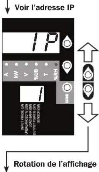
text_image
Voir l'adresse IP IP A KW Y %UB T H2% 1/1 INPUT PRICE (L) UNBLANED X (U) LOAD BAW (B) OUTPUT POWER (P) SENSOR (S) Rotation de l'affichagetext_image
0.3.0 INPUT PHASE (U) UNBALANCED % (U) LOAD BANK GM OUTPUT POWER (OP) SENSOR (S) 0.1 A KW V %UB T %RH MODE 0.6.0 INPUT PHASE (U) UNBALANCED % (U) LOAD BANK GM OUTPUT POWER (OP) SENSOR (S) 1.0 A KW V %UB T %RH MODEnatural_image
Simple line drawing of an electrical outlet with three slots (no text or symbols)C13 C19
natural_image
Simple line drawing of an electrical outlet with three slots and two rectangular outlets (no text or symbols)NEMA 5-15/20R

natural_image
Simple line drawing of a door with handle and door (no text or symbols)natural_image
Simple line drawing of two electrical socket sockets with a terminal pin (no text or symbols)DEL d'état du banc
text_image
OFF 20 ON Inatural_image
Simple line drawing of a door with a handle and screw base (no text or symbols)natural_image
Technical line drawing of a mechanical component with no visible text or symbols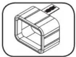
natural_image
Isometric line drawing of a rectangular mechanical component with a protruding rod (no text or symbols)

text_image
RESET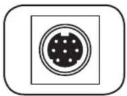
natural_image
Simple icon of a 3-pin connector inside a square frame (no text or symbols)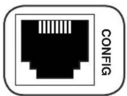
natural_image
Black and white icon of a Ethernet ports with 'CONFIG' text beside it (no additional symbols or text)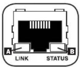
text_image
A LINK STATUS Btext_image
Communications Note Source: connection established with 10.0% or logged in the location PowerAlert Power Management Software TRIPP-LITE Device Device Actions Loop Preferences Data Device Details Plums DRIVERS Name: Device Name Type Device Name Location User: https://www.dcpower.com/2007 Device 1. All data set for every setting. Critical: Subscription Subscription Price SELECT NAME DETAILS Device Status Device Name Type Device Name Location User: http://www.dcpower.com/2007 Device 1. All data set for every setting. Device Name: Device Name: Device Name: Device Name: Device Name: Device Name: Device Name: Device Name: Device Name: Device Name: Device Name: Device Name: Device Name: Device Name: Device Name: Device Name: Device Name: Device Name: Device Name: Device Name: Device Name: Device Name: Device Name: Device Name: Device Name: Device Name: Device Name: Device Name: Device Name: Device Name: Device Name: Device Name: Device Name: Device Name: device name: device name: device name: device name: device name: device name: device name: device name: device name: device name: device name: device name: device name: device name: device name: device name: device name: device name: device name: device name: device name: device name: device name: device name: device name: device name: device name: device name: device name: device name: device name: device name: device name: device name:Entretien
1111 W. 35th Street, Chicago, IL 60609 USA • www.tripplite.com/support
Manufacturing Excellence.
1111 W. 35th Street, Chicago, IL 60609 USA • www.tripplite.com/support
natural_image
Diagram of a server rack with a directional arrow indicating movement, no text or symbols present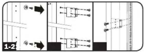
text_image
1-2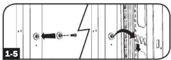
text_image
1-5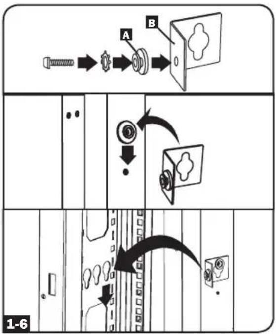
flowchart
graph TD
    A["Pinning Pin"] --> B["Close Button"]
    B --> C["Close Button"]
    C --> D["Window"]
    D --> E["Window"]
    E --> F["Window"]
    F --> G["Window"]
    G --> H["Window"]
    H --> I["Window"]
    I --> J["Window"]
    J --> K["Window"]
    K --> L["Window"]
    L --> M["Window"]
    M --> N["Window"]
    N --> O["Window"]
    O --> P["Window"]
    P --> Q["Window"]
    Q --> R["Window"]
    R --> S["Window"]
    S --> T["Window"]
    T --> U["Window"]
    U --> V["Window"]
    V --> W["Window"]
    W --> X["Window"]
    X --> Y["Window"]
    Y --> Z["Window"]
Установка
Подключение PDU

text_image
LINE L1-L2 L1- L2 2-3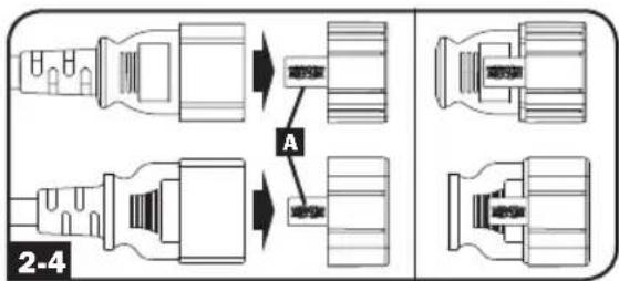
text_image
A 2-4flowchart
graph TD
    A["INPUT PHASE (L) UNBALANCED % UB LOAD BANK (BV) OUTPUT POWER (P) SENSOR (BV)"] --> B["INPUT PHASE (L) UNBALANCED % UB LOAD BANK (BV) OUTPUT POWER (P) SENSOR (BV)"]
    B --> C["OUTPUT POWER (P) SENSOR (BV)"]
    C --> D["INPUT PHASE (L) UNBALANCED % UB LOAD BANK (BV) OUTPUT POWER (P) SENSOR (BV)"]
    D --> E["OUTPUT POWER (P) SENSOR (BV)"]
    E --> F["INPUT PHASE (L) UNBALANCED % UB LOAD BANK (BV) OUTPUT POWER (P) SENSOR (BV)"]
    F --> G["OUTPUT POWER (P) SENSOR (BV)"]
    G --> H["INPUT PHASE (L) UNBALANCED % UB LOAD BANK (BV) OUTPUT POWER (P) SENSOR (BV)"]
    H --> I["OUTPUT POWER (P) SENSOR (BV)"]
    I --> J["INPUT PHASE (L) UNBALANCED % UB LOAD BANK (BV) OUTPUT POWER (P) SENSOR (BV)"]
    J --> K["OUTPUT POWER (P) SENSOR (BV)"]
    K --> L["INPUT PHASE (L) UNBALANCED % UB LOAD BANK (BV) OUTPUT POWER (P) SENSOR (BV)"]
    L --> M["OUTPUT POWER (P) SENSOR (BV)"]
    M --> N["INPUT PHASE (L) UNBALANCED % UB LOAD BANK (BV) OUTPUT POWER (P) SENSOR (BV)"]
    N --> O["OUTPUT POWER (P) SENSOR (BV)"]
    O --> P["INPUT PHASE (L) UNBALANCED % UB LOAD BANK (BV) OUTPUT POWER (P) SENSOR (BV)"]
    P --> Q["OUTPUT POWER (P) SENSOR (BV)"]
    Q --> R["INPUT PHASE (L) UNBALANCED % UB LOAD BANK (BV) OUTPUT POWER (P) SENSOR (BV)"]
    R --> S["OUTPUT POWER (P) SENSOR (BV)"]
    S --> T["INPUT PHASE (L) UNBALANCED % UB LOAD BANK (BV) OUTPUT POWER (P) SENSOR (BV)"]
    T --> U["OUTPUT POWER (P) SENSOR (BV)"]
    U --> V["INPUT PHASE (L) UNBALANCED % UB LOAD BANK (BV) OUTPUT POWER (P) SENSOR (BV)"]
    V --> W["OUTPUT POWER (P) SENSOR (BV)"]
    W --> X["INPUT PHASE (L) UNBALANCED % UB LOAD BANK (BV) OUTPUT POWER (P) SENSOR (BV)"]
    X --> Y["OUTPUT POWER (P) SENSOR (BV)"]
    Y --> Z["INPUT PHASE (L) UNBALANCED % UB LOAD BANK (BV) OUTPUT POWER (P) SENSOR (BV)"]
    Z --> AA["OUTPUT POWER (P) SENSOR (BV)"]
    AA --> AB["INPUT PHASE (L) UNBALANCED % UB LOAD BANK (BV) OUTPUT POWER (P) SENSOR (BV)"]
    AB --> AC["OUTPUT POWER (P) SENSOR (BV)"]
    AC --> AD["INPUT PHASE (L) UNBALANCED % UB LOAD BANK (BV) OUTPUT POWER (P) SENSOR (BV)"]
    AD --> AE["OUTPUT POWER (P) SENSOR (BV)"]
    AE --> AF["INPUT PHASE (L) UNBALANCED % UB LOAD BANK (BV) OUTPUT POWER (P) SENSOR (BV)"]
    AF --> AG["OUTPUT POWER (P) SENSOR (BV)"]
    AG --> AH["INPUT PHASE (L) UNBALANCED % UB LOAD BANK (BV) OUTPUT POWER (P) SENSOR (BV)"]
    AH --> AI["OUTPUT POWER (P) SENSOR (BV)"]
    AI --> AJ["INPUT PHASE (L) UNBALANCED % UB LOAD BANK (BV) OUTPUT POWER (P) SENSOR (BV)"]
    AJ --> AK["OUTPUT POWER (P) SENSOR (BV)"]
    AK --> AL["INPUT PHASE (L) UNBALANCED % UB LOAD BANK (BV) OUTPUT POWER (P) SENSOR (BV)"]
    AL --> AM["OUTPUT POWER (P) SENSOR (BV)"]
    AM --> AN["INPUT PHASE (L) UNBALANCED % UB LOAD BANK (BV) OUTPUT POWER (P) SENSOR (BV)"]
    AN --> AO["OUTPUT POWER (P) SENSOR (BV)"]
    AO --> AP["INPUT PHASE (L) UNBALANCED % UB LOAD BANK (BV) OUTPUT POWER (P) SENSOR (BV)"]
    AP --> AQ["OUTPUT POWER (P) SENSOR (BV)"]
    AQ --> AR["INPUT PHASE (L) UNBALANCED % UB LOAD BANK (BV) OUTPUT POWER (P) SENSOR (BV)"]
    AR --> AS["OUTPUT POWER (P) SENSOR (BV)"]
    AS --> AT["INPUT PHASE (L) UNBALANCED % UB LOAD BANK (BV) OUTPUT POWER (P) SENSOR (BV)"]
    AT --> AU["OUTPUT POWER (P) SENSOR (BV)"]
    AU --> AV["INPUT PHASE (L) UNBALANCED % UB LOAD BANK (BV) OUTPUT POWER (P) SENSOR (BV)"]
    AV --> AW["OUTPUT POWER (P) SENSOR (BV)"]
    AW --> AX["INPUT PHASE (L) UNBALANCED % UB LOAD BANK (BV) OUTPUT POWER (P) SENSOR (BV)"]
    AX --> AY["OUTPUT POWER (P) SENSOR (BV)"]
    AY --> AZ["INPUT PHASE (L) UNBALANCED % UB LOAD BANK (BV) OUTPUT POWER (P) SENSOR (BV)"]
    AZ --> BA["OUTPUT POWER (P) SENSOR (BV)"]
    BA --> BB["INPUT PHASE (L) UNBALANCED % UB LOAD BANK (BV) OUTPUT POWER (P) SENSOR (BV)"]
    BB --> BC["OUTPUT POWER (P) SENSOR (BV)"]
    BC --> BD["INPUT PHASE (L) UNBALANCED % UB LOAD BANK (BV) OUTPUT POWER (P) SENSOR (BV)"]
    BD --> BE["OUTPUT POWER (P) SENSOR (BV)"]
    BE --> BF["INPUT PHASE (L) UNBALANCED % UB LOAD BANK (BV) OUTPUT POWER (P) SENSOR (BV)"]
    BF --> BG["OUTPUT POWER (P) SENSOR (BV)"]
    BG --> BH["INPUT PHASE (L) UNBALANCED % UB LOAD BANK (BV) OUTPUT POWER (P) SENSOR (BV)"]
    BH --> BI["OUTPUT POWER (P) SENSOR (BV)"]
    BI --> BJ["INPUT PHASE (L) UNBALANCED % UB LOAD BANK (BV) OUTPUT POWER (P) SENSOR (BV)"]
    BJ --> BK["OUTPUT POWER (P) SENSOR (BV)"]
text_image
0 3.0 A KW V %UB T %RH INPUT PHASE (U) UNBALANCED % UB LOAD BANK SH OUTPUT POWER QPI SENSOR SH 0.1 ← 0'6.0 A KW V %UB T %RH 1.0 INPUT PHASE (U) UNBALANCED % UB LOAD BANK SH OUTPUT POWER QPI SENSOR SHnatural_image
Simple line drawing of an electrical outlet with three slots (no text or symbols)C13 C19
natural_image
Simple line drawing of an electrical outlet with three slots and two outside (no text or symbols)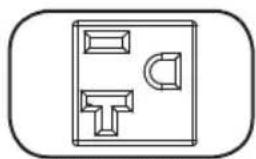
natural_image
Simple line drawing of a door with handle and door (no text or symbols)NEMA 5-15/20R
natural_image
Simple line drawing of two electrical socket sockets with a power outlet (no text or symbols)text_image
OFF 20 ON Inatural_image
Simple line drawing of a mechanical component with a handle and mounting base (no text or symbols)natural_image
Isometric line drawing of a mechanical component with no text or symbolsnatural_image
Isometric line drawing of a rectangular mechanical component with a protruding rod (no text or symbols)natural_image
Simple diagram of a circular connector with dot pattern inside a square frame (no text or symbols)natural_image
Black and white icon of an Ethernet ports with 'CONFIG' text beside it (no additional symbols or text)text_image
Communications Tools PowerAlert Sub-System with 10.0 Hz/Hz and logged in as local/min TRIPP-LITE PowerAlert Power Management Software Status Devices Actions Links Drivenes Help Demine Details Groups DEVICES Alarm Status: Voxel Name Type Device Name Location Timing: POWERMENTING CHILLI Critical: Black/Black/Black/Black Circuit: Black/Black/Black/Black SELECT ONE DETAILS Server Status Delivery Personal Technical Equatorial Name Group Value Units Internal Ctrl+Diverial Total Input Control Division Internal Ctrl+Diverial Total Input Control Division Internal Data Mode Rules Output Process Internal High Transfer Voltage Output 360 V Internal Load Frequency Output 19.9 V Internal Load Voltage Output 174.8 V Internal Low Transfer Voltage Output 25 V Internal Maximum Output Voltage Output 123.8 V Internal Maximum Output Current Output 27.7 V Internal Minimum Output Voltage Output 3.0 V Internal Minimum Output Duration Output 0.0 V, Total Internal Maximum Output Duration Output 0.0 V, Total Internal Maximum Output Power Grid Output 221 V Internal Output Distress Output 221 V Internal Output Duration Output 16.8 V Internal Maximum Output Duration Duration Output 36.0 V Internal Maximum Output Duration Duration Output 1.0 V1111 W. 35th Street, Chicago, IL 60609 USA • www.tripplite.com/support