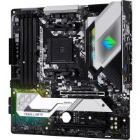
B550M Steel Legend - Motherboard ASROCK - Free user manual and instructions
Find the device manual for free B550M Steel Legend ASROCK in PDF.


User questions about B550M Steel Legend ASROCK
0 question about this device. Answer the ones you know or ask your own.
Ask a new question about this device
Download the instructions for your Motherboard in PDF format for free! Find your manual B550M Steel Legend - ASROCK and take your electronic device back in hand. On this page are published all the documents necessary for the use of your device. B550M Steel Legend by ASROCK.
USER MANUAL B550M Steel Legend ASROCK
Published April 2020
Copyright©2020 ASRock INC. All rights reserved.
Copyright Notice:
No part of this documentation may be reproduced, transcribed, transmitted, or translated in any language, in any form or by any means, except duplication of documentation by the purchaser for backup purpose, without written consent of ASRock Inc.
Products and corporate names appearing in this documentation may or may not be registered trademarks or copyrights of their respective companies, and are used only for identification or explanation and to the owners' benefit, without intent to infringe.
Disclaimer:
Specifications and information contained in this documentation are furnished for informational use only and subject to change without notice, and should not be constructed as a commitment by ASRock. ASRock assumes no responsibility for any errors or omissions that may appear in this documentation.
With respect to the contents of this documentation, ASRock does not provide warranty of any kind, either expressed or implied, including but not limited to the implied warranties or conditions of merchantability or fitness for a particular purpose.
In no event shall ASRock, its directors, officers, employees, or agents be liable for any indirect, special, incidental, or consequential damages (including damages for loss of profits, loss of business, loss of data, interruption of business and the like), even if ASRock has been advised of the possibility of such damages arising from any defect or error in the documentation or product.

This device complies with Part 15 of the FCC Rules. Operation is subject to the following two conditions:
(1) this device may not cause harmful interference, and
(2) this device must accept any interference received, including interference that may cause undesired operation.
CALIFORNIA, USA ONLY
The Lithium battery adopted on this motherboard contains Perchlorate, a toxic substance controlled in Perchlorate Best Management Practices (BMP) regulations passed by the California Legislature. When you discard the Lithium battery in California, USA, please follow the related regulations in advance.
"Perchlorate Material-special handling may apply, see www.dtsc.ca.gov/hazardouswaste/perchlorate"
ASRock Website: http://www.asrock.com

AUSTRALIA ONLY
Our goods come with guarantees that cannot be excluded under the Australian Consumer Law. You are entitled to a replacement or refund for a major failure and compensation for any other reasonably foreseeable loss or damage caused by our goods. You are also entitled to have the goods repaired or replaced if the goods fail to be of acceptable quality and the failure does not amount to a major failure. If you require assistance please call ASRock Tel: +886-2-28965588 ext.123 (Standard International call charges apply)
The terms HDMI^ and HDMI High-Definition Multimedia Interface, and the HDMI logo are trademarks or registered trademarks of HDMI Licensing LLC in the United States and other countries.

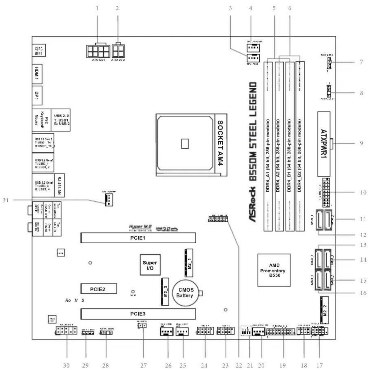
Motherboard Layout
No.Description
18 pin 12V Power Connector (ATX12V1)
24 pin 12V Power Connector (ATX12V2)
3 CPU Fan Connector (CPU_FAN1)
4 CPU/Water Pump Fan Connector (CPU_FAN2/WP)
5 2 x 288-pin DDR4 DIMM Slots (DDR4_A1, DDR4_B1)
6 2 x 288-pin DDR4 DIMM Slots (DDR4_A2, DDR4_B2)
7 RGB LED Header (RGB_LED1)
8 Addressable LED Header (ADDR_LED1)
9 ATX Power Connector (ATXPWR1)
10 USB 3.2 Gen1 Header (F_USB3_1_2)
11 SATA3 Connector (SATA3_2)
12 SATA3 Connector (SATA3_1)
13 SATA3 Connector (SATA3_4)
14 SATA3 Connector (SATA3_3)
15 SATA3 Connector (SATA3_5)
16 SATA3 Connector (SATA3_6)
17 System Panel Header (PANEL1)
18 Power LED and Speaker Header (SPK_PLED1)
19 USB 3.2 Gen1 Header (F_USB3_3_4)
20 Chassis/Water Pump Fan Connector (CHA_FAN4/WP)
21 Post Status Checker (PSC)
22 SPI TPM Header (SPI_TPM_J1)
23 USB 2.0 Header (USB_3_4)
24 USB 2.0 Header (USB_5_6)
25 Chassis/Water Pump Fan Connector (CHA_FAN2/WP)
26 Chassis/Water Pump Fan Connector (CHA_FAN3/WP)
27 Clear CMOS Jumper (CLRCMOS1)
28 Addressable LED Header (ADDR_LED2)
29 RGB LED Header (RGB_LED2)
30 Front Panel Audio Header (HD_AUDIO1)
31 Chassis/Water Pump Fan Connector (CHA_FAN1/WP)
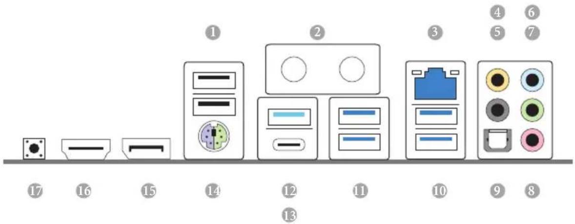
I/O Panel
No.Description No.Description
1 USB 2.0 Ports (USB_12)* 11 USB 3.2 Gen1 Ports
2 Antenna Ports (USB3_12)
(on I/O Panel Shield) 12 USB 3.2 Gen2 Type-A Port
3 LAN RJ-45 Port** (USB31_TA_1)
4 Central / Bass (Orange) 13 USB 3.2 Gen2 Type-C Port
5 Rear Speaker (Black) (USB31_TC_1)
6 Line In (Light Blue) 14 PS/2 Mouse/Keyboard Port
7 Front Speaker (Lime)***
15 DisplayPort 1.4
8 Microphone (Pink)
16 HDMI Port
9 Optical SPDIF Out Port 17 Clear CMOS Button
10 USB 3.2 Gen1 Ports (USB3_34)
- Please note that the USB_2 consumes auxiliary power (+5VSB) while the other USB ports consume DUAL Power (+5VDUAL). The USB_2 is optimal for connecting the USB Type speaker and headset.
There are two LEDs on each LAN port. Please refer to the table below for the LAN port LED indications.
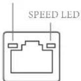
ACT/LINKLED
LAN Port
| Activity / Link LED Speed LED | ||
| Status Description Status Description | ||
| Off No Link Off | 10Mbps connection | |
| Blinking Data Activity Orange | 100Mbps/1Gbps connection | |
| On Link Green 2.5Gbps connection | ||
If you use a 2-channel speaker, please connect the speaker's plug into "Front Speaker Jack". See the table below for connection details in accordance with the type of speaker you use.
| Audio Output Channels | Front Speaker (No. 7) | Rear Speaker (No.5) | Central / Bass (No. 4) | Line In (No. 6) |
| 2 V -- -- | ||||
| 4 V V -- | ||||
| 6 V V V -- | ||||
| 8 V V V V |
Chapter 1 Introduction
Thank you for purchasing ASRock B550M Steel Legend motherboard, a reliable motherboard produced under ASRock's consistently stringent quality control. It delivers excellent performance with robust design conforming to ASRock's commitment to quality and endurance.

Because the motherboard specifications and the BIOS software might be updated, the content of this documentation will be subject to change without notice. In case any modifications of this documentation occur, the updated version will be available on ASRock's website without further notice. If you require technical support related to this motherboard, please visit our website for specific information about the model you are using. You may find the latest VGA cards and CPU support list on ASRock's website as well. ASRock website http://www.asrock.com.
1.1 Package Contents
ASRock B550M Steel Legend Motherboard (Micro ATX Form Factor)
ASRock B550M Steel Legend Quick Installation Guide
ASRock B550M Steel Legend Support CD
- 2 × Serial ATA (SATA) Data Cables (Optional)
- 2 × Screws for M.2 Socket (Optional)
1.2 Specifications
| Platform | • Micro ATX Form Factor • 2oz Copper PCB |
| CPU | • Supports 3rdGen AMD AM4 RyzenTM / future AMD RyzenTM Processors (3000 and 4000 Series Processors)* • Not compatible with AMD Athlon™ Processors. • Digi Power design • 10 Power Phase design |
| Chipset | • AMD B550 |
| Memory | • Dual Channel DDR4 Memory Technology • 4x DDR4 DIMM Slots • AMD Ryzen series CPUs (Matisse) support DDR4 4533+(OC)/4466(OC)/4400(OC)/4333(OC)/4266(OC)/4200(OC)/4133(OC)/4000(OC)/3866(OC)/3800(OC)/3733 (OC)/3600(OC)/3466(OC)/3200/2933/2667/2400/2133 ECC & non-ECC, un-buffered memory* • AMD Ryzen series APUs (Renoir) support DDR4 4733+(OC)/4666(OC)/4600(OC)/4533(OC)/4466(OC)/4400(OC)/4333(OC)/4266(OC)/4200(OC)/4133(OC)/4000(OC)/3866(OC)/3800(OC)/3733(OC)/3600(OC)/3466(OC)/3200/2933/2667/2400/2133 ECC & non-ECC, un-buffered memory* • Please refer to Memory Support List on ASRock's website for more information. (http://www.asrock.com/) • Please refer to page 22 for DDR4 UDIMM maximum frequency support. • Max. capacity of system memory: 128GB • Supports Extreme Memory Profile (XMP) memory modules • 15μ Gold Contact in DIMM Slots |
| Expansion Slot | AMD Ryzen series CPUs (Matisse) • 2x PCI Express x16 Slots (PCIE1: Gen4x16 mode; PCIE3: Gen3 x4 mode)* AMD Ryzen series APUs (Renoir) • 2x PCI Express x16 Slots (PCIE1: Gen3x16 mode; PCIE3: Gen3 x4 mode)* • Supports NVMe SSD as boot disks • 1x PCI Express 3.0 x1 Slot |
Supports AMD Quad CrossFireX™ and CrossFireX™
15μ Gold Contact in VGA PCIe Slot (PCIE1)
- 1 x M.2 Socket (Key E), supports type 2230 WiFi/BT module
Graphics
- Integrated AMD Radeon™ Vega Series Graphics in Ryzen Series APU*
-
Actual support may vary by CPU
-
DirectX 12, Pixel Shader 5.0
-
Shared memory default 2GB. Max Shared memory supports up to 16GB.
-
The Max shared memory 16GB requires 32GB system memory installed.
Supports HDMI 2.1 with max. resolution up to 4K× 2K (4096x2160) @ 60Hz
Supports DisplayPort 1.4 with max. resolution up to 5K (5120x2880)@120Hz
Supports Auto Lip Sync, Deep Color (12bpc), xvYCC and HBR (High Bit Rate Audio) with HDMI 2.1 Port (Compliant HDMI monitor is required)
Supports HDR (High Dynamic Range) with HDMI 2.1
Supports HDCP 2.3 with HDMI 2.1 and DisplayPort 1.4 Ports
Supports 4K Ultra HD (UHD) playback with HDMI 2.1 and DisplayPort 1.4 Ports
Supports Microsoft PlayReady
Audio
7.1 CH HD Audio with Content Protection (Realtek ALC1200 Audio Codec)
- Premium Blu-ray Audio support
Supports Surge Protection
PCB Isolate Shielding
- Individual PCB Layers for R/L Audio Channel
Gold Audio Jacks
- Nahimic Audio
LAN
2.5 Gigabit LAN 10/100/1000/2500 Mb/s
- Dragon RTL8125BG
Supports Dragon 2.5G LAN Software
- Smart Auto Adjust Bandwidth Control
- Visual User Friendly UI
- Visual Network Usage Statistics
- Optimized Default Setting for Game, Browser, and Streaming Modes
-User Customized Priority Control
Supports Wake-On-LAN
Supports Lightning/ESD Protection
Supports Energy Efficient Ethernet 802.3az
Supports PXE
Rear Panel
I/O
- 2 x Antenna Ports (on I/O Panel Shield)
- 1 x PS/2 Mouse/Keyboard Port
- 1 x HDMI Port
1xDisplayPort1.4
1 x Optical SPDIF Out Port - 1 x USB 3.2 Gen2 Type-A Port (10 Gb/s) (Supports ESD Protection)
- 1 x USB 3.2 Gen2 Type-C Port (10 Gb/s) (Supports ESD Protection)
- 4 x USB 3.2 Gen1 Ports (ASMedia ASM1074 hub) (Supports ESD Protection)
- 2 x USB 2.0 Ports (Supports ESD Protection)
- 1 x RJ-45 LAN Port with LED (ACT/LINK LED and SPEED LED)
- 1 x Clear CMOS Button
- HD Audio Jacks: Rear Speaker / Central / Bass / Line in / Front Speaker / Microphone (Gold Audio Jacks)
Storage
-
6 x SATA3 6.0 Gb/s Connectors, support RAID (RAID 0, RAID 1 and RAID 10), NCQ, AHCI and Hot Plug*
-
M2_2 and SATA3_5_6 share lanes. If either one of them is in use, the other one will be disabled.
-
1 x Hyper M.2 Socket (M2_1), supports M Key type 2280 M.2 PCI Express module up to Gen4x4 (64 Gb/s) (with Matisse) or Gen3x4 (32 Gb/s) (with Renoir)**
-
1 x M.2 Socket (M2_2), supports M Key type 2280 M.2 SATA3 6.0 Gb/s module and M.2 PCI Express module up to Gen3 x2 (16 Gb/s)
Supports NVMe SSD as boot disks
**Supports ASRock U.2 Kit
Connector
- 1xSPI TPM Header
- 1 x Power LED and Speaker Header
-
2xRGBLEDHeaders
-
Support in total up to 12V/3A, 36W LED Strip
-
2 × Addressable LED Headers
- Support in total up to 5V/3A, 15W LED Strip
-
1 x CPU Fan Connector (4-pin)
-
The CPU Fan Connector supports the CPU fan of maximum 1A (12W) fan power.
-
1 x CPU/Water Pump Fan Connector (4-pin) (Smart Fan Speed Control)
-
4 x Chassis/Water Pump Fan Connectors (4-pin) (Smart Fan Speed Control)
-
The Chassis/Water Pump Fan supports the water cooler fan of maximum 2A (24W) fan power.
-
CPU_FAN2/WP, CHA_FAN1/WP, CHA_FAN2/WP, CHA_FAN3/WP and CHA_FAN4/WP can auto detect if 3-pin or 4-pin fan is in use.
-
1 x 24 pin ATX Power Connector (Hi-Density Power Connector)
- 1 × 8 pin 12V Power Connector (Hi-Density Power Connector)
- 1 × 4 pin 12V Power Connector (Hi-Density Power Connector)
- 1 x Front Panel Audio Connector
- 2 x USB 2.0 Headers (Support 4 USB 2.0 ports) (Supports ESD Protection)
- 2 x USB 3.2 Gen1 Headers (Support 4 USB 3.2 Gen1 ports) (Supports ESD Protection)
| BIOS Feature | · AMI UEFI Legal BIOS with GUI support · Supports “Plug and Play” · ACPI 5.1 compliance wake up events · Supports jumperfree · SMBIOS 2.3 support · CPU, CPU VDDCR SOC, DRAM, VPPM, 1.05V PROM_S5, 2.5V PROM, +1.8VSB, VDDP Voltage Multi-adjustment |
| Hardware Monitor | · Temperature Sensing: CPU, CPU/Water Pump, Chassis/Water Pump Fans · Fan Tachometer: CPU, CPU/Water Pump, Chassis/Water Pump Fans · Quiet Fan (Auto adjust chassis fan speed by CPU temperature): CPU, CPU/Water Pump, Chassis/Water Pump Fans · Fan Multi-Speed Control: CPU, CPU/Water Pump, Chassis/Water Pump Fans · Voltage monitoring: +12V, +5V, +3.3V, CPU Vcore, CPU VDDCR SOC, DRAM, VPPM, 1.05V PROM_S5, +1.8V, VDDP |
| OS | · Microsoft® Windows® 10 64-bit |
| Certifica- tions | · FCC, CE · ErP/EuP ready (ErP/EuP ready power supply is required) |
- For detailed product information, please visit our website: http://www.asrock.com
Please realize that there is a certain risk involved with overclocking, including adjusting the setting in the BIOS, applying Untied Overclocking Technology, or using third-party overclocking tools. Overclocking may affect your system's stability, or even cause damage to the components and devices of your system. It should be done at your own risk and expense. We are not responsible for possible damage caused by overclocking.
Chapter 2 Installation
This is a Micro ATX form factor motherboard. Before you install the motherboard, study the configuration of your chassis to ensure that the motherboard fits into it.
Pre-installation Precautions
Take note of the following precautions before you install motherboard components or change any motherboard settings.
- Make sure to unplug the power cord before installing or removing the motherboard. Failure to do so may cause physical injuries to you and damages to motherboard components.
- In order to avoid damage from static electricity to the motherboard's components, NEVER place your motherboard directly on a carpet. Also remember to use a grounded wrist strap or touch a safety grounded object before you handle the components.
- Hold components by the edges and do not touch the ICs.
- Whenever you uninstall any components, place them on a grounded anti-static pad or in the bag that comes with the components.
- When placing screws to secure the motherboard to the chassis, please do not overtighten the screws! Doing so may damage the motherboard.
2.1 Installing the CPU

Unplug all power cables before installing the CPU.
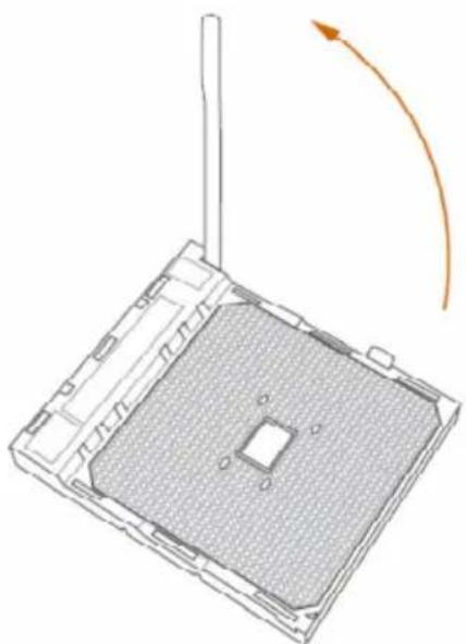
1
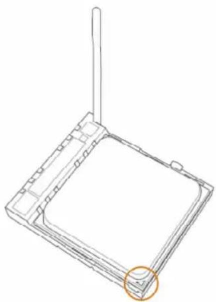
2
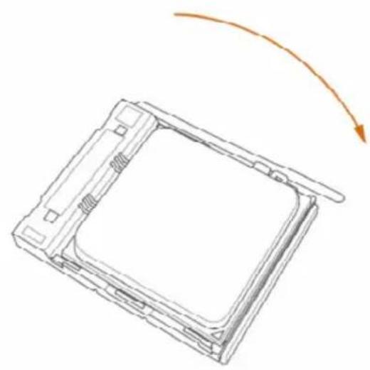
3
2.2 Installing the CPU Fan and Heatsink
After you install the CPU into this motherboard, it is necessary to install a larger heatsink and cooling fan to dissipate heat. You also need to spray thermal grease between the CPU and the heatsink to improve heat dissipation. Make sure that the CPU and the heatsink are securely fastened and in good contact with each other.

Please turn off the power or remove the power cord before changing a CPU or heatsink.
Installing the CPU Box Cooler SR1
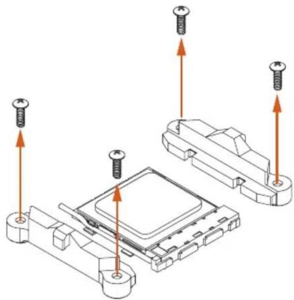
1
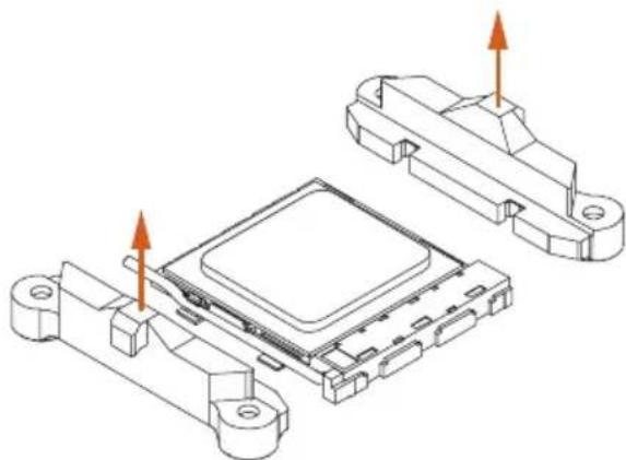
2
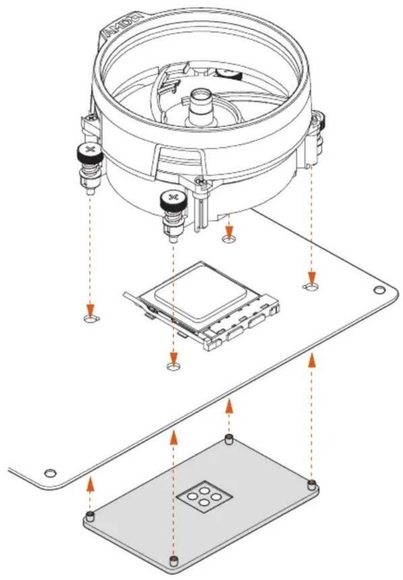
3
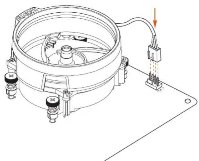
4
Installing the AM4 Box Cooler SR2
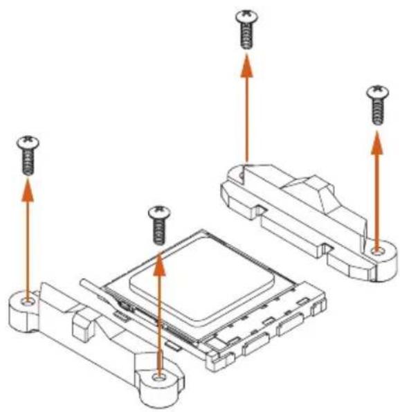
1
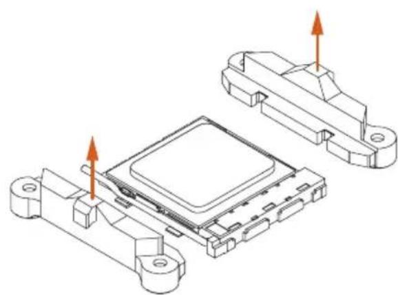
2
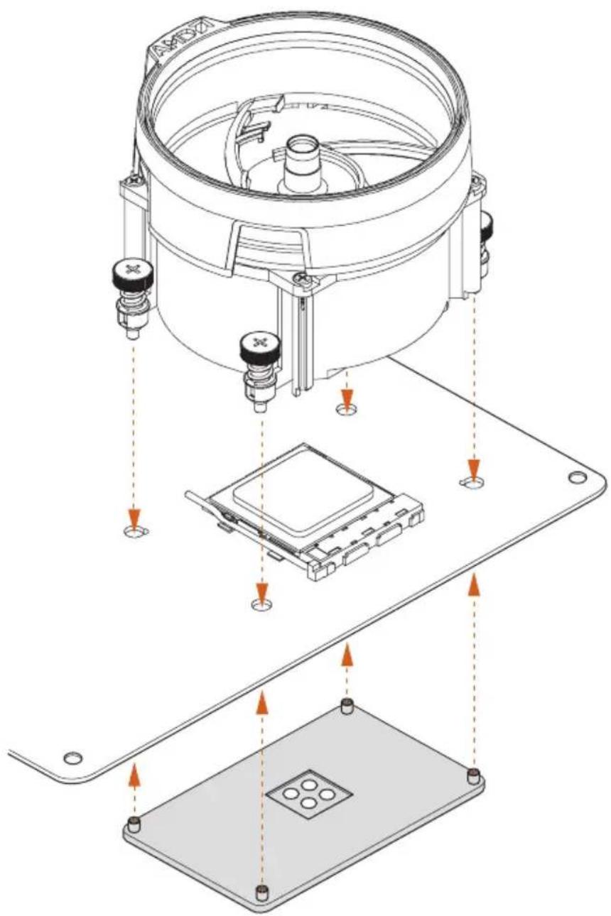
3
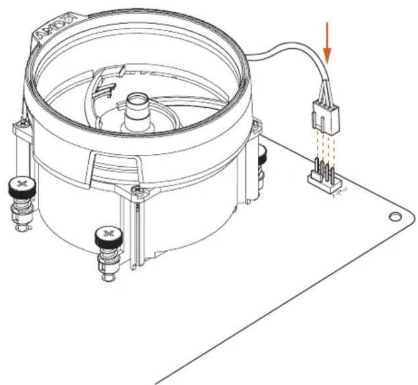
4
*The diagrams shown here are for reference only. The headers might be in a different position on your motherboard.
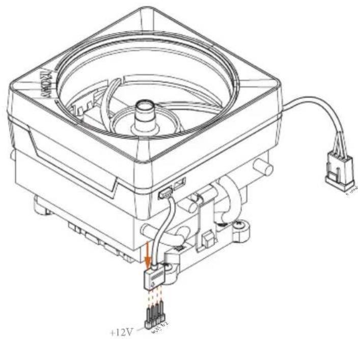
Installing the AM4 Box Cooler SR3
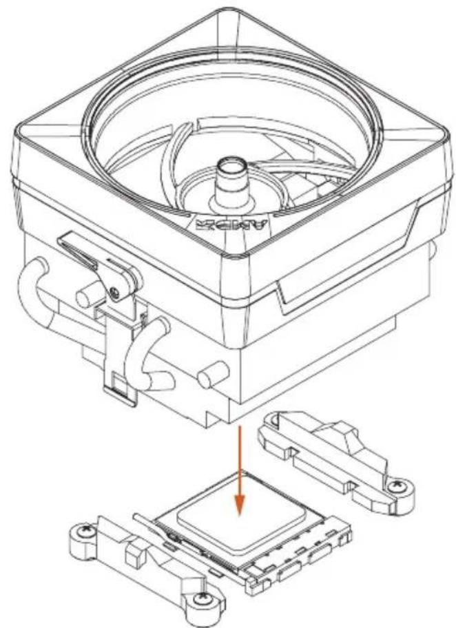
1
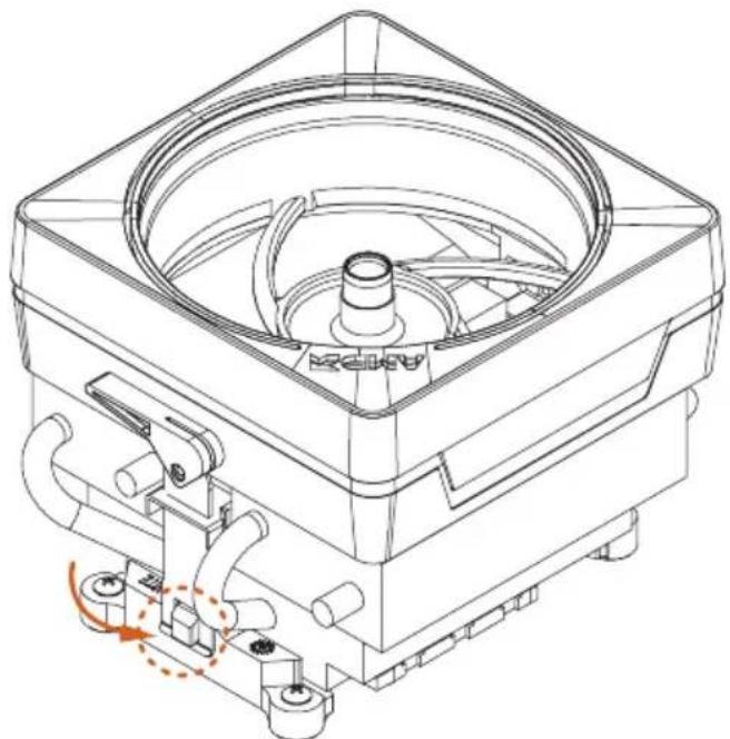
2
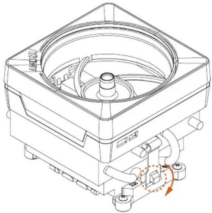
3
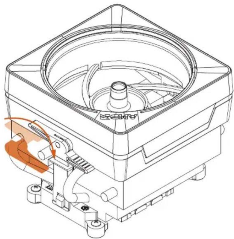
4
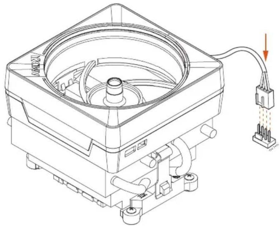
5
6
*The diagrams shown here are for reference only. The headers might be in a different position on your motherboard.
2.3 Installing Memory Modules (DIMM)
This motherboard provides four 288-pin DDR4 (Double Data Rate 4) DIMM slots, and supports Dual Channel Memory Technology.

- For dual channel configuration, you always need to install identical (the same brand, speed, size and chip-type) DDR4 DIMM pairs.
- It is unable to activate Dual Channel Memory Technology with only one or three memory module installed.
- It is not allowed to install a DDR, DDR2 or DDR3 memory module into a DDR4 slot; otherwise, this motherboard and DIMM may be damaged.
- We suggest that you install the memory modules on DDR4_A2 and DDR4_B2 first for better DRAM compatibility on 2 DIMMs configuration.
AMD non-XMP Memory Frequency Support
Ryzen Series CPUs (Matisse):
UDIMM Memory Slot
A1 A2 B1 B2
Frequency
(Mhz)
- SR - - 3200
-DR--3200 - SR - SR 3200
-DR-DR3200
SR SR SR SR 2933
SR/DR DR SR/DR DR 2667
SR/DR SR/DR SR/DR SR/DR
2667
Ryzen Series APUs (Renoir):
| UDIMM Memory Slot | Frequency |
| A1 A2 B1 B2 | (Mhz) |
- SR - - 3200
-DR--3200
- SR - SR 3200
-DR-DR3200
SR SR SR SR 2933
SR/DR DR SR/DR DR 2667
SR/DR SR/DR SR/DR SR/DR 2667
SR: Single rank DIMM, 1Rx4 or 1Rx8 on DIMM module label
DR: Dual rank DIMM, 2Rx4 or 2Rx8 on DIMM module label

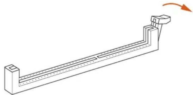
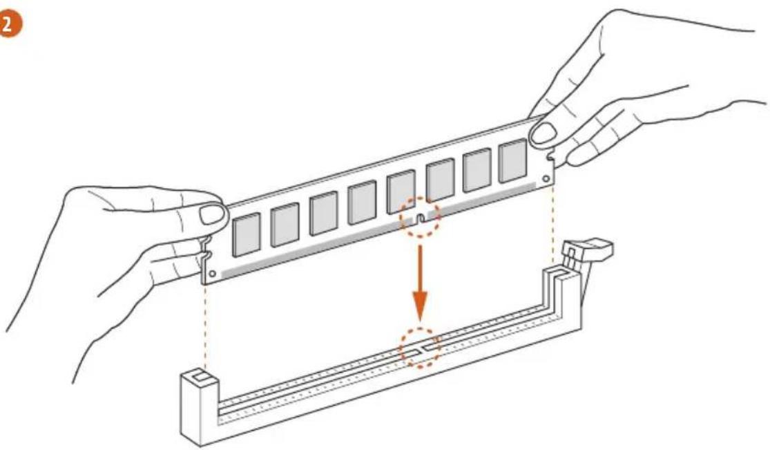
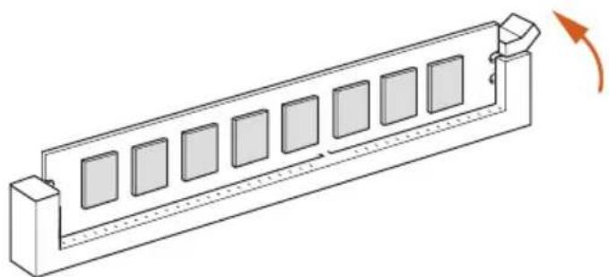
The DIMM only fits in one correct orientation. It will cause permanent damage to the motherboard and the DIMM if you force the DIMM into the slot at incorrect orientation.
1
2
3
2.4 Expansion Slots (PCI Express Slots)
There are 3 PCI Express slots on the motherboard.

Before installing an expansion card, please make sure that the power supply is switched off or the power cord is unplugged. Please read the documentation of the expansion card and make necessary hardware settings for the card before you start the installation.
PCIe slots:
PCIE1 (PCIe 4.0 x16 slot) is used for PCI Express x16 lane width graphics cards.
PCIE2 (PCIe 3.0 x1 slot) is used for PCI Express x1 lane width cards.
PCIE3 (PCIe 3.0 x16 slot) is used for PCI Express x4 lane width graphics cards.
PCIe Slot Configurations
| PCIE1 PCIE2 PCIE3 | |||
| Ryzen Series CPUs (Matisse) | Gen4x16 | Gen3x1 | Gen3x4 |
| Ryzen Series CPUs (Renoir) | Gen3x16 | Gen3x1 | Gen3x4 |

For a better thermal environment, please connect a chassis fan to the motherboard's chassis fan connector (CHA_FAN1/WP, CHA_FAN2/WP, CHA_FAN3/WP or CHA_FAN4/WP) when using multiple graphics cards.
2.5 Jumpers Setup
The illustration shows how jumpers are setup. When the jumper cap is placed on the pins, the jumper is "Short". If no jumper cap is placed on the pins, the jumper is "Open".
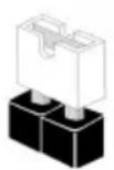
Short
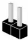
Open
Clear CMOS Jumper
(CLRCMOS1)
(see p.1, No. 27)

2-pin Jumper
Short: Clear CMOS
Open: Default
CLRCMOS1 allows you to clear the data in CMOS. The data in CMOS includes system setup information such as system password, date, time, and system setup parameters. To clear and reset the system parameters to default setup, please turn off the computer and unplug the power cord, then use a jumper cap to short the pins on CLRCMOS1 for 3 seconds. Please remember to remove the jumper cap after clearing the CMOS. If you need to clear the CMOS when you just finish updating the BIOS, you must boot up the system first, and then shut it down before you do the clear-CMOS action.

The Clear CMOS Button has the same function as the Clear CMOS jumper.
2.6 Onboard Headers and Connectors

Onboard headers and connectors are NOT jumpers. Do NOT place jumper caps over these headers and connectors. Placing jumper caps over the headers and connectors will cause permanent damage to the motherboard.
System Panel Header (9-pin PANEL1) (see p.1, No. 17)
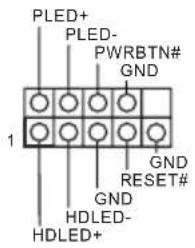
Connect the power button, reset button and system status indicator on the chassis to this header according to the pin assignments below. Note the positive and negative pins before connecting the cables.

PWRBTN (Power Button):
Connect to the power button on the chassis front panel. You may configure the way to turn off your system using the power button.
RESET (Reset Button):
Connect to the reset button on the chassis front panel. Press the reset button to restart the computer if the computer freezes and fails to perform a normal restart.
PLED (System Power LED):
Connect to the power status indicator on the chassis front panel. The LED is on when the system is operating. The LED keeps blinking when the system is in S1/S3 sleep state. The LED is off when the system is in S4 sleep state or powered off (S5).
HDLED (Hard Drive Activity LED):
Connect to the hard drive activity LED on the chassis front panel. The LED is on when the hard drive is reading or writing data.
The front panel design may differ by chassis. A front panel module mainly consists of power button, reset button, power LED, hard drive activity LED, speaker and etc. When connecting your chassis front panel module to this header, make sure the wire assignments and the pin assignments are matched correctly.
Power LED and Speaker Header
(7-pin SPK_PLED1)
(see p.1, No. 18)
SPEAKER
DUMMY
DUMMY
+5V
1
PLED+
PLED+
PLED-
Please connect the
chassis power LED and
the chassis speaker to this
header.
Serial ATA3 Connectors
(SATA3_1:
see p.1, No. 12)
(SATA3_2:
see p.1, No. 11)
(SATA3_3:
see p.1, No. 14)
(SATA3_4:
see p.1, No. 13)
(SATA3_5:
see p.1, No. 15)
(SATA3_6:
see p.1, No. 16)
aannnnnne aannnnnne
5 5
These six SATA3
connectors support SATA
data cables for internal
storage devices with up to
6.0 Gb/s data transfer rate.
- M2_2 and SATA3_5_6
share lanes. If either one
of them is in use, the other
one will be disabled.
USB 2.0 Headers
(9-pin USB_3_4)
(see p.1, No. 23)
(9-pin USB_5_6)
(see p.1, No. 24)
USB PWR
P-
GND DUMMY
1
GND
4
USB_PWR
There are two headers
on this motherboard.
Each USB 2.0 header can
support two ports.
USB 3.2 Gen1 Headers
(19-pin F_USB3_1_2)
(see p.1, No. 10)
Vbus
VbusVbus
IntA_PB_SSRX
IntA_PB_SSR
GND
IntA_PB_SSTX
IntA_PB_SSTX+
GND
GND
IntA_PB_D-
A_D-
IntA_PB_D+
intA.
Dummy
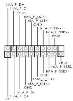
There are two headers on
this motherboard. Each
USB 3.2 Gen1 header can
support two ports.
(19-pin F_USB3_3_4)
(see p.1, No. 19)
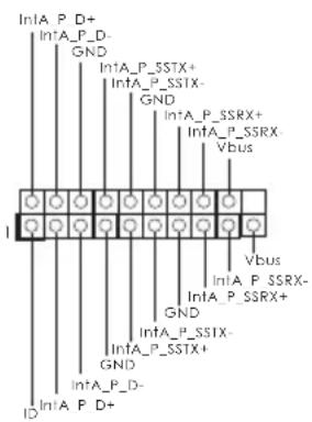
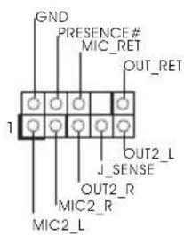
Front Panel Audio Header (9-pin HD AUDIO1) (see p.1, No. 30)
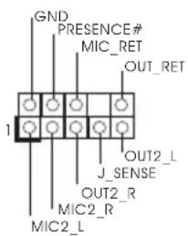
This header is for connecting audio devices to the front audio panel.

- High Definition Audio supports Jack Sensing, but the panel wire on the chassis must support HDA to function correctly. Please follow the instructions in our manual and chassis manual to install your system.
- If you use an AC'97 audio panel, please install it to the front panel audio header by the steps below:
A. Connect Mic_IN (MIC) to MIC2_L.
B. Connect Audio_R (RIN) to OUT2_R and Audio_L (LIN) to OUT2_L.
C. Connect Ground (GND) to Ground (GND).
D. MIC_RET and OUT_RET are for the HD audio panel only. You don't need to connect them for the AC'97 audio panel.
E. To activate the front mic, go to the "FrontMic" Tab in the Realtek Control panel and adjust "Recording Volume".
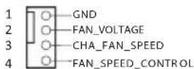
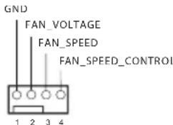
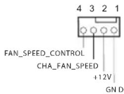
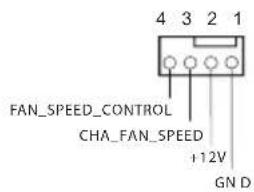
Chassis Water Pump Fan Connectors
(4-pin CHA_FAN1/WP)
(see p.1, No. 31)
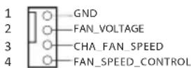
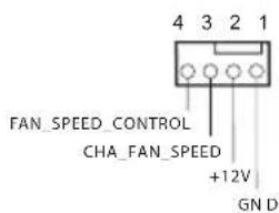
This motherboard provides four 4-Pin water cooling chassis fan connectors. If you plan to connect a 3-Pin chassis water cooler fan, please connect it to Pin 1-3.
(4-pin CHA_FAN2/WP)
(see p.1, No. 25)
(4-pin CHA_FAN3/WP)
(see p.1, No. 26)
(4-pin CHA_FAN4/WP)
(see p.1, No. 20)
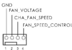
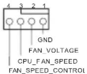
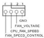
CPU Fan Connector
(4-pinCPU_FAN1)
(see p.1, No. 3)
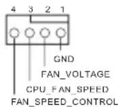
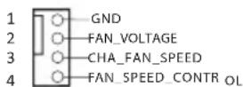
This motherboard provides a 4-Pin CPU fan
(Quiet Fan) connector.
If you plan to connect a 3-Pin CPU fan, please connect it to Pin 1-3.
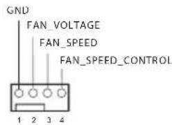
CPU Water Pump Fan
Connector
(4-pin CPU_FAN2/WP)
(see p.1, No. 4)
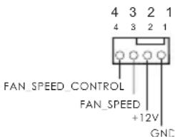
This motherboard provides a 4-Pin water cooling CPU fan
connector. If you plan to connect a 3-Pin CPU water cooler fan, please connect it to Pin 1-3.
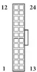
ATX Power Connector
(24-pin ATXPWR1)
(see p.1, No. 9)
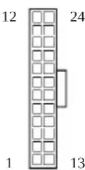
This motherboard provides a 24-pin ATX power connector. To use a 20-pin ATX power supply, please plug it along Pin 1 and Pin 13.
ATX 12V Power Connector (8-pin ATX12V1) (see p.1, No. 1)
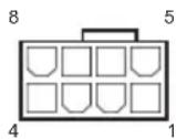
This motherboard provides an 8-pin ATX 12V power connector. To use a 4-pin ATX power supply, please plug it along Pin 1 and Pin 5.
*Warning: Please make sure that the power cable connected is for the CPU and not the graphics card. Do not plug the PCIe power cable to this connector.
ATX 12V Power Connector (4-pin ATX12V2) (see p.1, No.2)
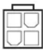
Please connect an ATX 12V power supply to this connector.
Connecting an ATX 12V 4-pin cable here is optional.
The power supply plug fits into this connector in only one orientation.
SPI TPM Header (13-pin SPI_TPM_J1) (see p.1, No.22)
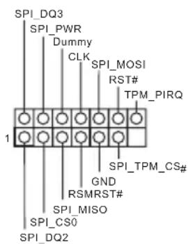
This connector supports SPI Trusted Platform Module (TPM) system, which can securely store keys, digital certificates, passwords, and data. A TPM system also helps enhance network security, protects digital identities, and ensures platform integrity.
| RGB LED Headers (4-pin RGB_LED1) (see p.1, No. 7) | 1 B R G +12V | These two RGB headers are used to connect RGB LED extension cable which allows users to choose from various LED lighting effects. Caution: Never install the RGB LED cable in the wrong orientation; otherwise, the cable may be damaged. *Please refer to page 43 for further instructions on these two headers. |
| (4-pin RGB_LED2) (see p.1, No. 29) | 1 +12VG R B | |
| Addressable LED Headers (3-pin ADDR_LED1) (see p.1, No. 8) | 1 VOUT DO_ADDR GND | These two Addressable headers are used to connect Addressable LED extension cable which allows users to choose from various LED lighting effects. Caution: Never install the Addressable LED cable in the wrong orientation; otherwise, the cable may be damaged. *Please refer to page 44 for further instructions on this header. |
| (3-pin ADDR_LED2) (see p.1, No. 28) | 1 1 DO_ADDR VOUT |
2.7 Clear CMOS Button
The motherboard has a Clear CMOS Button, allowing users to quickly clear the CMOS values.
Clear CMOS Button
(CLRCBTN1)
(see p.3, No. 17)

Clear CMOS Button
allows users to quickly
clear the CMOS values.

This function is workable only when you power off your computer and unplug the power supply.
2.8 Post Status Checker
Post Status Checker (PSC) diagnoses the computer when users power on the machine. It emits a red light to indicate whether the CPU, memory, VGA or storage is dysfunctional. The lights go off if the four mentioned above are functioning normally.
2.9 M.2 WiFi/BT Module Installation Guide (M2_3)
The M.2, also known as the Next Generation Form Factor (NGFF), is a small size and versatile card edge connector that aims to replace mPCIe and mSATA. The M.2 Socket (Key E) supports type 2230 WiFi/BT module.
- The M.2 socket does not support SATA M.2 SSDs.
Installing the WiFi/BT module
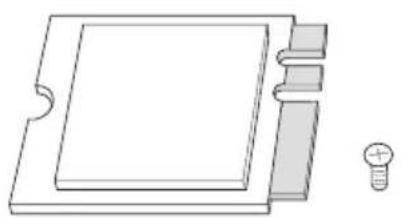
Step 1
Prepare a type 2230 WiFi/BT module and the screw.
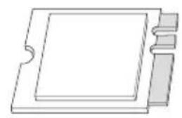
Step 2
Find the nut location to be used.
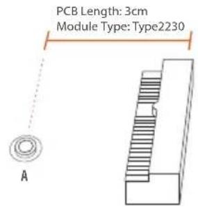
Step 3
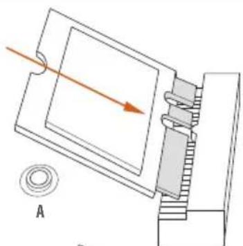
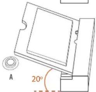
Gently insert the WiFi/BT module into the M.2 slot. Please be aware that the module only fits in one orientation.
Step 4
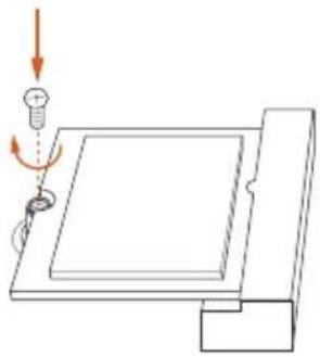
Tighten the screw with a screwdriver to secure the module into place. Please do not overtighten the screw as this might damage the module.
2.10 M.2_SSD (NGFF) Module Installation Guide (M2_1)
The M.2, also known as the Next Generation Form Factor (NGFF), is a small size and versatile card edge connector that aims to replace mPCIe and mSATA.
The Hyper M.2 Socket (M2_1) supports M Key type 2280 M.2 PCI Express module up to Gen4x4 (64 Gb/s) (with Matisse) or Gen3x4 (32 Gb/s) (with Renoir).
Installing the M.2_SSD (NGFF) Module
Step 1
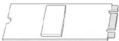
Prepare a M.2_SSD (NGFF) module and the screw.
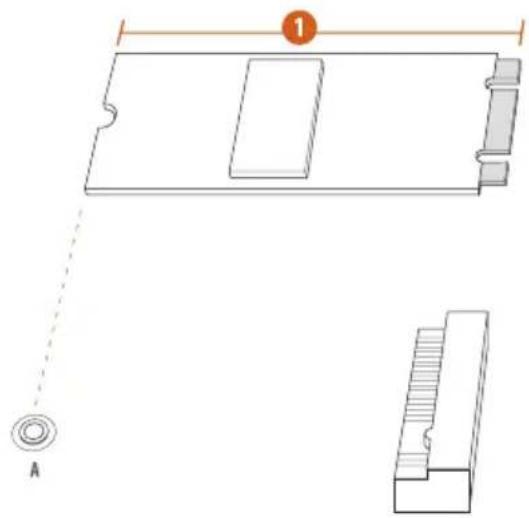
Step 2
Depending on the PCB type and length of your M.2_SSD (NGFF) module, find the corresponding nut location to be used.
No.1
Nut Location A
PCB Length 8cm
Module Type Type2280
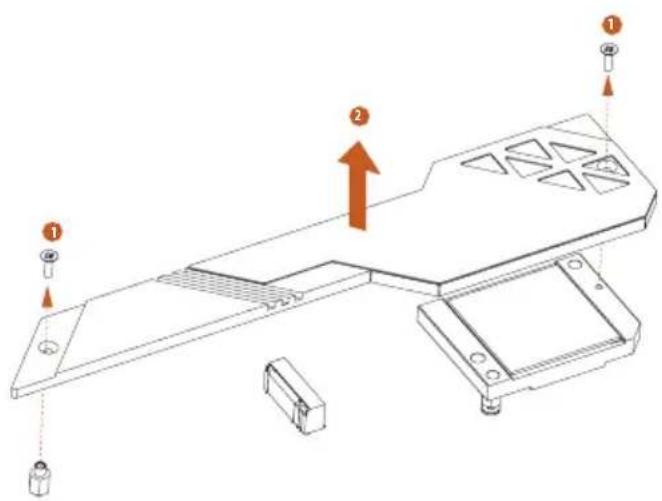
Step 3
Before installing a M.2 (NGFF) SSD module, please loosen the screws to remove the M.2 heatsink.
*Please remove the protective films on the bottom side of the M.2 heatsink before you install a M.2 SSD module.
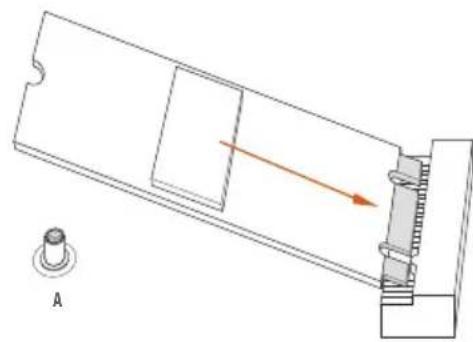
Step 4
Align and gently insert the M.2 (NGFF) SSD module into the M.2 slot. Please be aware that the M.2 (NGFF) SSD module only fits in one orientation.
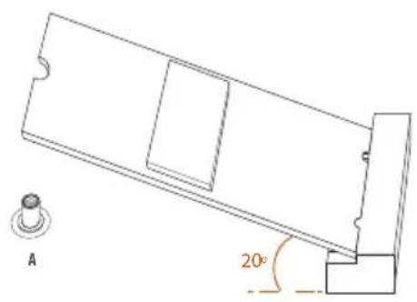
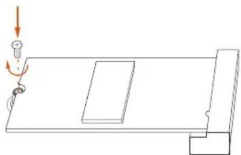
Step 5
Tighten the screw with a screwdriver to secure the module into place. Please do not overtighten the screw as this might damage the module.
M.2_SSD (NGFF) Module Support List (M2_1)
| Vendor Interface P/N | ||
| ADATA PCIe3 x4 ASX7000NP-128GT-C | ||
| ADATA PCIe3 x4 ASX8000NP-256GM-C | ||
| ADATA PCIe3 x4 ASX7000NP-256GT-C | ||
| ADATA PCIe3 x4 ASX8000NP-512GM-C | ||
| ADATA PCIe3 x4 ASX7000NP-512GT-C | ||
| Apacer PCIe3 x4 AP240GZ280 | ||
| Corsair PCIe3 x4 CSSD-F240GBMP500 | ||
| Intel PCIe3 x4 SSDPEKKF256G7 | ||
| Intel PCIe3 x4 SSDPEKKF512G7 | ||
| Kingston PCIe3 x4 SKC1000/480G | ||
| Kingston PCIe2 x4 SH2280S3/480G | ||
| OCZ PCIe3 x4 RVD400 -M2280-512G (NVME) | ||
| PATR IOT PCIe3 x4 PH240GPM280SSDR NVME | ||
| Plextor PCIe3 x4 PX-128M8PeG | ||
| Plextor PCIe3 x4 PX-1TM8PeG | ||
| Plextor PCIe3 x4 PX-256M8PeG | ||
| Plextor PCIe3 x4 PX-512M8PeG | ||
| Plextor PCIe | PX-G256M6e | |
| Plextor PCIe | PX-G512M6e | |
| Samsung | PCIe3 x4 | SM961 MZVPW128HEGM (NVM) |
| Samsung | PCIe3 x4 | PM961 MZVLW128HEGR (NVME) |
| Samsung | PCIe3 x4 | 960 EVO (MZ-V6E250) (NVME) |
| Samsung | PCIe3 x4 | 960 EVO (MZ-V6E250BW) (NVME) |
| Samsung | PCIe3 x4 SM951 (NVME) | |
| Samsung | PCIe3 x4 | SM951 (MZHPV256HDGL) |
| Samsung | PCIe3 x4 | SM951 (MZHPV512HDGL) |
| Samsung | PCIe3 x4 SM951 (NVME) | |
| Samsung | PCIe x4 | XP941-512G (MZHPU512HCGL) |
| SanDisk | PCIe | SD6PP4M-128G |
| SanDisk | PCIe | SD6PP4M-256G |
| TEAM | PCIe3 x4 TM8FP2240G0C101 | |
| TEAM | PCIe3 x4 TM8FP2480GC110 | |
| WD | PCIe3 x4 WDS256G1X0C-00ENX0 (NVME) | |
| WD | PCIe3 x4 WDS512G1X0C-00ENX0 (NVME) | |
For the latest updates of M.2_SSD (NFGG) module support list, please visit our website for details: http://www.asrock.com
2.11 M.2_SSD (NGFF) Module Installation Guide (M2_2)
The M.2, also known as the Next Generation Form Factor (NGFF), is a small size and versatile card edge connector that aims to replace mPCIe and mSATA. The M.2 Socket (M2_2) supports M Key type 2280 M.2 SATA3 6.0 Gb/s module and M.2 PCI Express module up to Gen3 x2 (16 Gb/s).
- M2_2 and SATA3_5_6 share lanes. If either one of them is in use, the other one will be disabled.
Installing the M.2_SSD (NGFF) Module
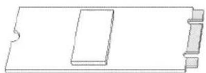
Step 1
Prepare a M.2_SSD (NGFF) module and the screw.
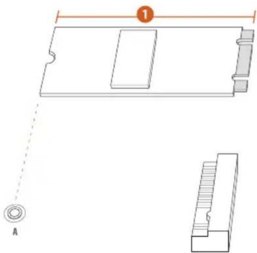
Step 2
Depending on the PCB type and length of your M.2_SSD (NGFF) module, find the corresponding nut location to be used.
No.1
Nut Location A
PCB Length 8cm
Module Type Type2280
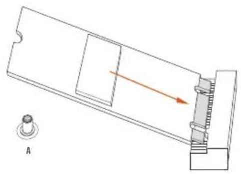
Step 3
Align and gently insert the M.2
(NGFF) SSD module into the M.2
slot. Please be aware that the M.2
(NGFF) SSD module only fits in one orientation.
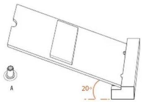
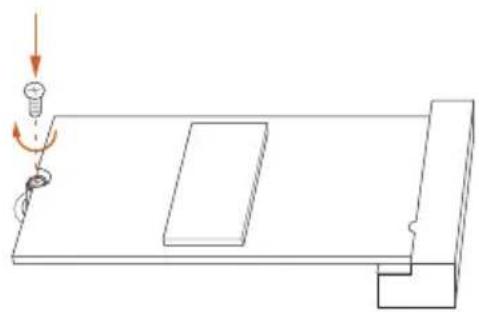
Step 4
Tighten the screw with a screwdriver to secure the module into place.
Please do not overtighten the screw as this might damage the module.
M.2_SSD (NGFF) Module Support List (M2_2)
| Vendor Interface P/N | |
| ADATA SATA3 AXNS330E-32GM-B | |
| ADATA SATA3 AXNS381E-128GM-B | |
| ADATA SATA3 AXNS381E-256GM-B | |
| ADATA SATA3 ASU800NS38-256GT-C | |
| ADATA SATA3 ASU800NS38-512GT-C | |
| Crucial SATA3 CT120M500SSD4 | |
| Crucial SATA3 CT240M500SSD4 | |
| Intel SATA3 Intel SSDSCGKW080A401/80G | |
| Kingston SATA3 SM2280S3 | |
| Plextor PCIe PX-G256M6e | |
| Plextor PCIe PX-G512M6e | |
| Samsung PCIe x4 XP941-512G (MZHPU512HCGL) | |
| SanDisk PCIe SD6PP4M-128G | |
| SanDisk PCIe SD6PP4M-256G | |
| Team SATA3 TM4PS4128GMC105 | |
| Team SATA3 TM4PS4256GMC105 | |
| Team SATA3 TM8PS4128GMC105 | |
| Team SATA3 TM8PS4256GMC105 | |
| Transcend SATA3 TS256GMTS400 | |
| Transcend SATA3 TS512GMTS600 | |
| Transcend SATA3 TS512GMTS800 | |
| V-Color SATA3 VLM100-120G-2280B-RD | |
| V-Color SATA3 VLM100-240G-2280RGB | |
| V-Color SATA3 VSM100-240G-2280 | |
| V-Color SATA3 VLM100-240G-2280B-RD | |
| WD SATA3 WDS100T1B0B-00AS40 | |
| WD SATA3 WDS240G1G0B-00RC30 |
For the latest updates of M.2_SSD (NFGG) module support list, please visit our website for details: http://www.asrock.com
2.12 ASRock Polychrome SYNC
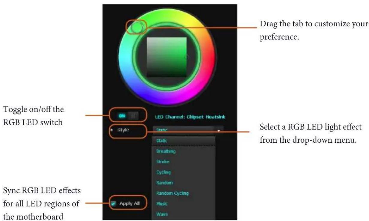
ASRock Polychrome SYNC is a lighting control utility specifically designed for unique individuals with sophisticated tastes to build their own stylish colorful lighting system. Simply by connecting the LED strip, you can customize various lighting schemes and patterns, including Static, Breathing, Strobe, Cycling, Music, Wave and more.
Connecting the LED Strip
Connect your RGB LED strips to the RGB LED Headers (RGB_LED1, RGB_LED2) on the motherboard.
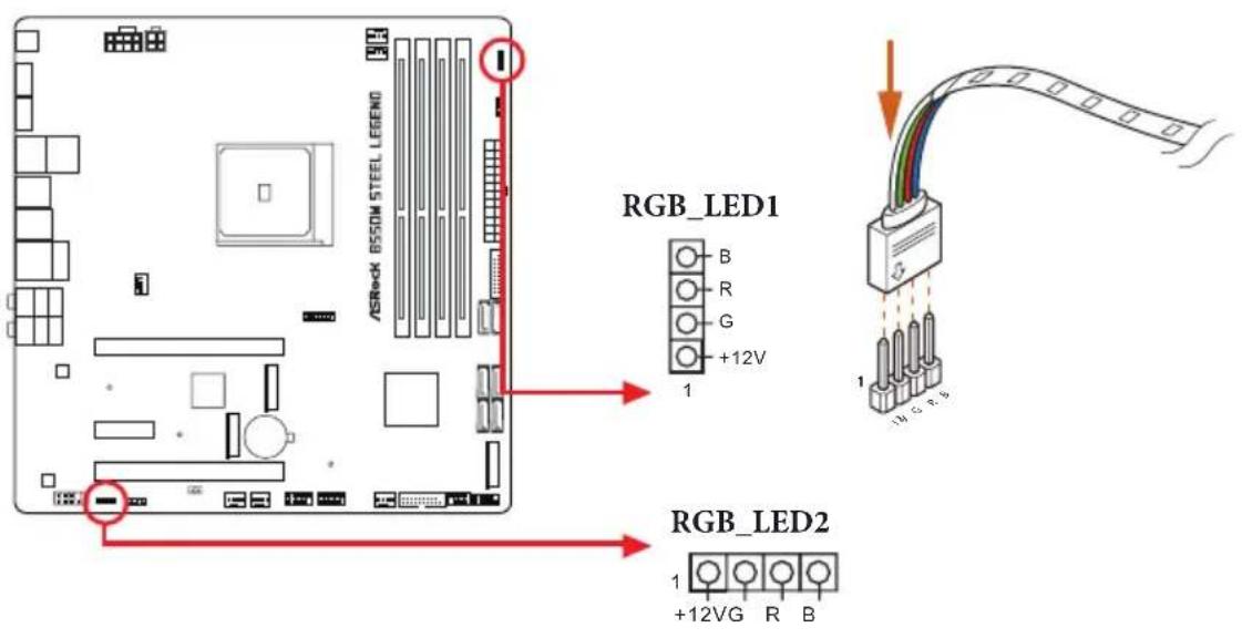

- Never install the RGB LED cable in the wrong orientation; otherwise, the cable may be damaged.
- Before installing or removing your RGB LED cable, please power off your system and unplug the power cord from the power supply. Failure to do so may cause damages to motherboard components.

- Please note that the RGB LED strips do not come with the package.
- The RGB LED header supports standard 5050 RGB LED strip (12V/G/R/B), with a maximum power rating of 3A (12V) and length within 2 meters.
Connecting the Addressable RGB LED Strip
Connect your Addressable RGB LED strips to the Addressable LED Headers (ADDR_LED1, ADDR_LED2) on the motherboard.
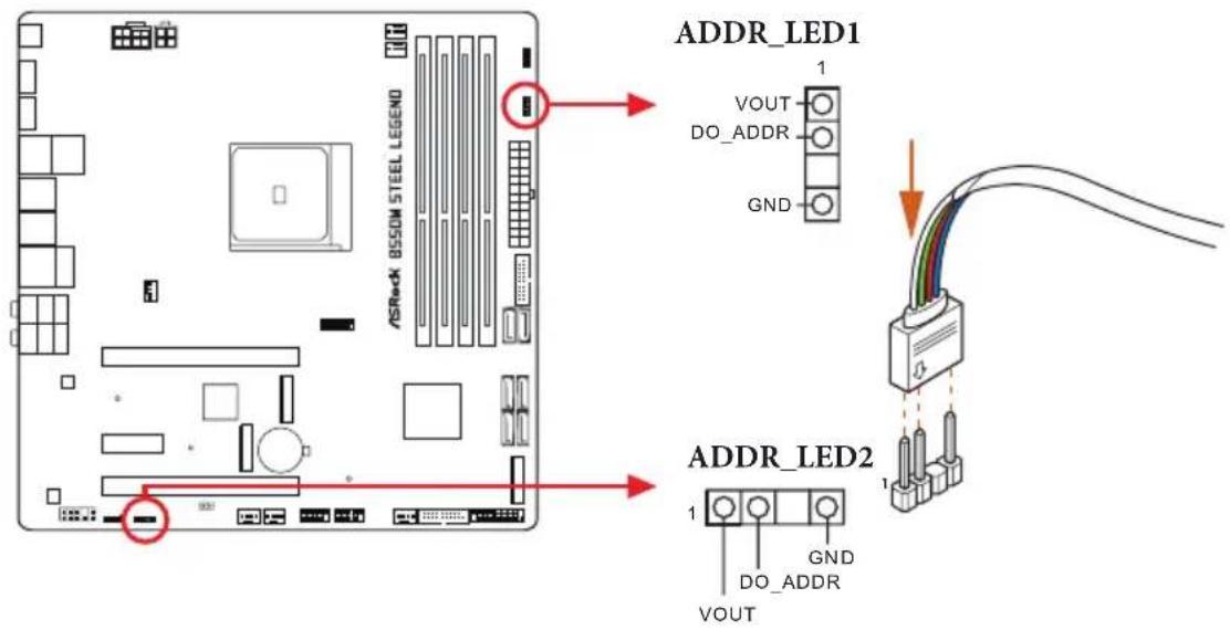

- Never install the RGB LED cable in the wrong orientation; otherwise, the cable may be damaged.
- Before installing or removing your RGB LED cable, please power off your system and unplug the power cord from the power supply. Failure to do so may cause damages to motherboard components.

- Please note that the RGB LED strips do not come with the package.
- The RGB LED header supports WS2812B addressable RGB LED strip (5V/Data/GND), with a maximum power rating of 3A (5V) and length within 2 meters.
ASRock Polychrome SYNC Utility
Now you can adjust the RGB LED color through the ASRock Polychrome SYNC Utility. Download this utility from the ASRock Live Update & APP Shop and start coloring your PC style your way!
1 Einleitung
(4-polig, CHA_FAN1/WP)
(siehe S.1, Nr.31)
(4-polig, CPU_FAN2/WP)
(siehe S.1,Nr.4)
** Supporta kit ASRock U.2
Connettore
(CHA_FAN1/WP a 4 pin)
Tasto Cancella CMOS (CLRCBTN1)
TbIOBbie nopTbI BBOda-BbIBOda
2 aHTeHHbIX IopTa (Ha IIaHeII C IIOPTaMn BBOJa-BBIOJa)
1 nopr PS/2 mMbHn/KJIaBnAtypbI
- 1 nopr HDMI
- 1 nopTr DisplayPort 1.4
1 OIIITUeCKN BbIXoD SPDIF
1 nopT USB 3.2 Gen2 Type-A (10 Γ6nt/c) (c 3auntoi ot ΘeKtpocTaTuuecknx pa3pnoB)
1 nopt USB 3.2 Gen2 Type-C (10 6nt/c) (c 3auntoi or 3neKtpoctaTuecknx pa3pnoB)
- 4 nopToB USB 3.2 Gen1 (ASMedia ASM1074 hub) (c 3aunToiO T 3JIeKTPoCtataTnuecknx pa3pIIOB)
2 npra USB 2.0 (c 3aunToI OT 9JIeKTPoCTaTnuecknx pa3pIIOB)
1 IopT JBC RJ-45 c HnIkaTopaMn («AKTNBHOCTb/ CoeHHeHne» N «Ckopoctb»)
1 KhoIIka c6poca hactpoek CMOS
Pa3bEmbHDAudio:TbIOBbIEAC/ueHTpaIbHaAC/ ca6Byep/INHeIHbIBBXoI/ΦpoHTaIbHbIEAC/MNKpOΦOH (IO30IOUeHHbIE KOHTaKTbl)
3anomnhaoune yctpoictba
6 IopTa SATA3 co cKOpocTbIO IpepaH JaHHbIX 6,0 T6HT/c, IopIepkKa RAID (RAID 0, RAID 1 n RAID 10), NCQ, AHCI n «Topaero IoIKIIOueHnra.
*O6uue KaHaJIbI M2_2, n SATA3_5_6. Ecnn nCIOJIb3yETcOINH 13 ETNX IByX CIOTOB, BTOPOI 6yIeT OTKIIHOyeH.
1 cIoT Hyper M.2 (M2_1), ΠΟДΕρχΝΑeΤσ ΜΟΥΙΝΜ.2 PCI Express TnIa 2280 c KΠΟΥΟ M ΜΟΒερςιν Gen4 x4 (64 Γ6nt/c) (c Matisse) έπιν Gen3 x4 (32 Γ6nt/c) (c Renoir)**
1x cnot M.2 (M2_2), IOndepKINBaET MOyIb M.2 SATA3 TnIIa 2280 c npOlycKHOI cIOco6HocTbIO 6,0 6NT / c nMOyIb M.2 PCI Express IO Bercn Gen3 x2 (16 6NT / c)^**
Ha MaTePnHcKoI INaTe NMeeTcA
ДБЕ кОLOДКИ. Кждя кОLOДКА
USB3.2 Gen1 nOuepKnBaet
ДВа порта.
(19 KOHTaKTOB,
F_USB3_3_4)
(cm. cTp. 1, No 19)
AynokoiKa IpeHneiHaHei
(9-KoHTaKTOB, HD_
AUDIO1)
(cM. cTp. 1, No 30)
Ta KIOKa IIpeHa3HaueHa
IIa IIOKIOUeHn
ayIOOyCTPOIcTB K IpeIHe
ayIOHaHEI.

- Ayoduocumema bblcokozopaseuiennoodepkuabaem fyHKuio pacno3haaunpa3bema, no dya en paabunbHou paobmheo6xodmo, umobn npo0do naenu Kopnyca nodoepkuan nepedauy cueano8 HDA. Hcmpykuu no ycmaohoke cucmembu cm. 8 mom pykoobodme u pykoobodme ha kopnyc.
- IIpu ucnonbsobahu ayduonaheu AC'97 nooknqume ee k ayduokonodke nepednei naheu, ka ykaana doanee:
A.Поdkнουуme Mic_IN (MIC) κ MIC2_L.
B. Iodkaoume Audio_R (RIN) κ OUT2_R, Audio_L (LIN) κ OUT2_L.
C. Hoekkoume npo0o3a3emuen (GND) K konhmaky 3a3emuen (GND).
D. Konmkmu MIC_RET u OUT_RET uonnbmycm monbko dny ayduonanenu bvcok020 paspeuenu. Ipu uonnb3obauu ayduonanenu AC'97 ux nodknoaum he hkykno.
E. Ymobsakmuupobambnepehui Mukpofo,nepeudume na klaadky FrontMic nanenu ynpaenue Realtek u ompezynupyune napamemp Recording Volume (Tpomkocmbanucu).
Pa3bEmblIeBHTINITopa
IIMI IOMII BODHO
OxIaJKeHnKoPnYca
(4-KOHTaKTHbI CHA_
FAN1/WP)
(cm. cTp. 1, No 31)
JHHaCNCTeMHHa
IIaTa OcHaIeHa YeTbIpe
4-KOHTaKTHbIMpa3beMaMnIJIa
CNCTeMbI BOJHHO OXJaKHeHn
KOpIyca.3-KoHTaKTHyIO
CNCTeMy BOJIAHOO XIaXJIeHnI
Kopnyca cneyet NOkNIOuTaB K
KOHTaKTam 1-3.
(4-KOHTaKTbI CHA
FAN2/WP)
(cm. ctp. 1, No 25)
(4-KoHTaKTHbI CHA_ FAN3/WP)
(cm. cTp. 1, No 26)
(4-KoHTaKTbI CHA FAN4/WP)
(cm. ctp. 1, No 20)
Pa3bem BeHTnIaTopa oxJaXeHnI npOeCCopa
(4-KoHTaKaTa, CPU_FAN1)
(cM.cTp.1,N3)
Ta MaTePnHcKa IHaTa cHa6KeHa
4-KoHTaKTHbIM pa3beMOM IJIa
MaIOUyMnIeTO BeHTNlAToPA
II.I.EcIN BbI co6uPaTeCb
IOIKJIOuHTb 3-KoHTaKTHbI
BeHTNlAToPOXlaJxJDeHn
IpoIeCCopa,IOKJIIOuaTe erO K KOHTaKTam 1-3.
Pa3bEm IJIa BeHTnIaTopa HIN IOMIIb BOJHO OxJaXdEHHI
(4-KoHTaKTHbIe CPU FAN2/WP)
(cm.ctp.1,N4)
IaHHa MaTePnHcKa IHaTa OchHaHeHa 4-KoHTaKTHbIM pa3beMOM IIa CnCTeMb BOJHOrO OxJaKeHnI II.3-KoHTaKTHyIO cnCTeMy BOJHOrO OxJaKeHnI III cneJyET IOJKnIOuATb K KOHTaKTam 1-3.
Pa3bEm IITaHnA TX
(24-KoHTaKaTa,ATXPWR1)
(cM. cTp. 1, N9 9)
Ta MaTePnHcKa IIaTa
OchaueHa 24-KoHTaKTHbIM
pa3bEMOM INTaHnA ATX. Yo6bl
NCIOJIb3OBA Tb 20-KoHTaKTHbI
pa3bEm IITaHnA ATX,
IOIKJIIOUHTe ERO BIOJIb KOHTaKTA
1 N KOHTaKTA 13.
(4) CHA_FAN2/WP)
(1.0iJ,25
(4 CHA_FAN3/WP)
(1.3019,26
(4 CHA_FAN4/WP)
(1.0iJ,20
CPU 建筑代码
(4 CPU_FAN1)
(1.30)
i MaTBeBtEeN 4 CPU
(J)K)K
TaeHn.3CPU
1-3 e enen
CPU 命题 范例
(4.1 CPU_FAN2/WP)
(1.30i,4.2
If you need to contact ASRock or want to know more about ASRock, you're welcome to visit ASRock's website at http://www.asrock.com; or you may contact your dealer for further information. For technical questions, please submit a support request form at http://www.asrock.com/support/tsd.asp
ASRock Incorporation
2F., No.37, Sec. 2, Jhongyang S. Rd., Beitou District,
Taipei City 112, Taiwan (R.O.C.)
ASRock EUROPE B.V.
Bijsterhuizen 11-11
6546 AR Nijmegen
The Netherlands
Phone: +31-24-345-44-33
Fax: +31-24-345-44-38
ASRock America, Inc.
13848 Magnolia Ave, Chino, CA91710
U.S.A.
Phone: +1-909-590-8308
Fax: +1-909-590-1026
DECLARATION OF CONFORMITY
Per FCC Part 2 Section 2.1077(a)

Responsible Party Name: ASRock Incorporation
Address: 13848 Magnolia Ave, Chino, CA91710
Phone/Fax N o: +1-909-590-8308/+1-909-590-1026
hereby declares that the product
Product Name : Motherboard
Model Number: B550M Steel Legend
Conforms to the following specifications:
FCCPart15,SubpartB,Unintentional Radiators
Supplementary Information:
This device complies with part 15 of the FCC Rules. Operation is subject to the following two conditions: (1) This device may not cause harmful interference, and (2) this device must accept any interference received, including interference that may cause undesired operation.
Representative Person's Name: James
Signature:
Date: May 12, 2017
EU Declaration of Conformity
ASRock
For the following equipment:
Motherboard
(Product Name)
B550M Steel Legend/ ASRock
(Model Designation / Trade Name)
ASRock Incorporation
(Manufacturer Name)
2F., No.37, Sec. 2, Zhongyang S. Rd., Beitou District, Taipei City 112, Taiwan (R.O.C.)
(Manufacturer Address)
EMC—Directive 2014/30/EU (from April 20th, 2016)
EN 55022:2010/AC:2011 Class B
EN55024:2010/A1:2015
EN55032:2012+AC:2013 Class B
EN61000-3-3:2013
EN61000-3-2:2014
□LVD—Directive 2014/35/EU (from April 20th,2016)
EN60950-1:2011+A2:2013
EN 60950-1:2006/A12:2011
RoHS- Directive 2011/65/EU
CE marking
(EU conformity marking)
C E
ASRock EUROPE B.V.
(Company Name)
Bijsterhuizen 1111 6546 AR Nijmegen The Netherlands
(Company Address)
Person responsible for making this declaration:
(Name, Surname)
A.V.P
(Position / Title)
May 27, 2020
(Date)
P/N:15G062228000AK V1.0