
DDR1527SDC - Monitor stand Tripp Lite - Free user manual and instructions
Find the device manual for free DDR1527SDC Tripp Lite in PDF.

| Product Type | Dual Monitor Desk Mount |
| Brand | Tripp Lite |
| Model | DDR1527SDC |
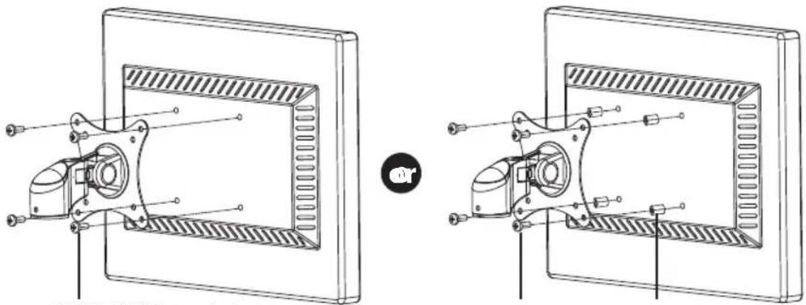
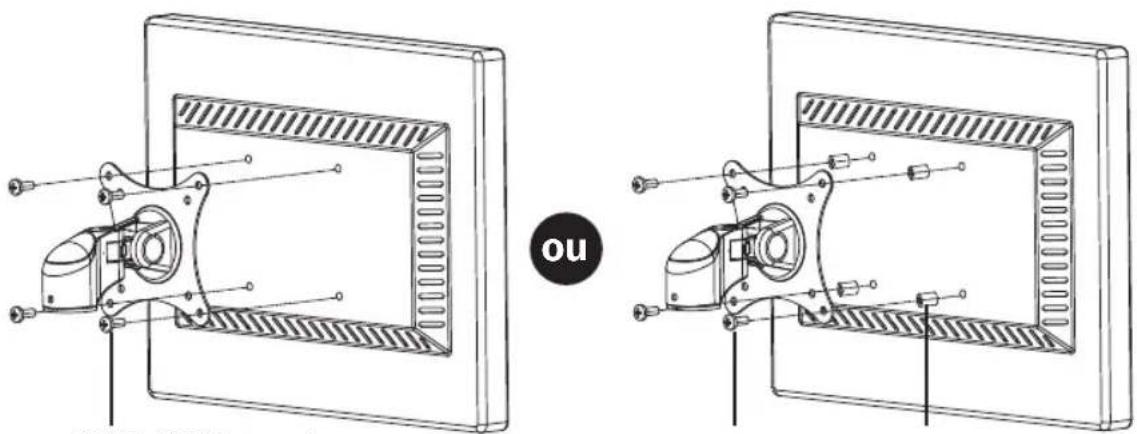
| VESA Compatible | Yes (VESA plates included, M4 and M6 screws) |
| Number of Screens Supported | 2 |
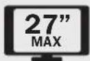
| Maximum Screen Size | 27 inches (approximate) |
| Maximum Weight per Screen | 8 kg (estimated) |
| Mounting Method | Clamp or Grommet Mount (hole in desk) |
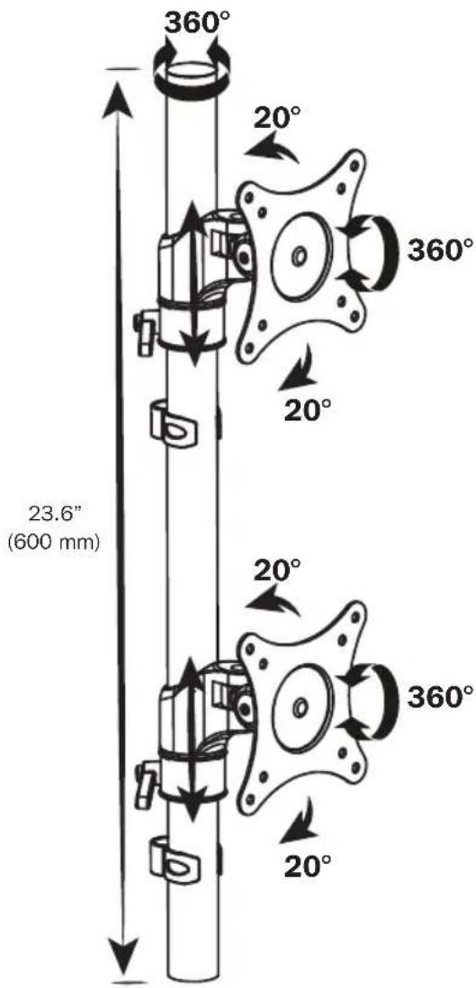
| Height Adjustment Range | 600 mm (23.6 in) |
| Tilt | 20° forward/backward |
| Rotation | 360° per screen |
| Swivel | 360° per screen |
| Material | Steel / Aluminum |
| Cable Management | Yes (cable ties included) |
| Color | Black (common) |
| Dimensions (W x D x H) | 800 x 200 x 600 mm (estimated) |
| Mount Weight | 7 kg (estimated) |
| Power Supply | None (manual mounting) |
| Warranty | 5 years (limited warranty) |
| Package Contents | Pole, base, clamp, VESA plates (x2), spacers, screws, Allen keys (3,4,5 mm), cable ties, tip, centering washers |
Frequently Asked Questions - DDR1527SDC Tripp Lite
User questions about DDR1527SDC Tripp Lite
0 question about this device. Answer the ones you know or ask your own.
Ask a new question about this device
Download the instructions for your Monitor stand in PDF format for free! Find your manual DDR1527SDC - Tripp Lite and take your electronic device back in hand. On this page are published all the documents necessary for the use of your device. DDR1527SDC by Tripp Lite.
USER MANUAL DDR1527SDC Tripp Lite
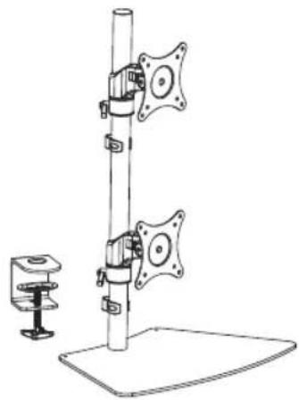
Dual Vertical Flat Screen Desk or Clamp Mount
MODEL: DDR1527SDC
natural_image
Technical line drawing of a mechanical device with a vertical pole, two mounting brackets, and a base platform (no text or symbols)Español 9 • Français 17 • Русский 25 • Deutsch 33

CAUTION: DO NOT EXCEED MAXIMUM LISTED WEIGHT CAPACITY. SERIOUS INJURY OR PROPERTY DAMAGE MAY OCCUR!

75 × 75 100 × 100

PROTECT YOUR INVESTMENT!
Register your product for quicker service and ultimate peace of mind.
You could also win an ISOBAR6ULTRA
surge protector—a \$100 value!
www.tripplite.com/warranty


1111 W. 35th Street, Chicago, IL 60609 USA • www.tripplite.com/support
Copyright © 2015 Tripp Lite. All rights reserved.
NOTE: Read the entire instruction manual before you start installation and assembly.

WARNING
- Do not begin the installation until you have read and understood the instructions and warnings contained in this manual. If you have any questions regarding any of the instructions or warnings, please visit www.triplite.com/support.
- This mounting bracket was designed to be installed and utilized ONLY as specified in this manual. Improper installation of this product may cause damage or serious injury.
- This product should only be installed by someone of good mechanical ability, with basic building experience and a full understanding of this instruction manual.
- Make sure that the mounting surface can safely support the combined load of the equipment and all attached hardware and components.
- If mounting to wood wall studs, make sure that mounting screws are anchored into the center of the studs. The use of a stud finder is highly recommended.
- Always use an assistant or mechanical lifting equipment to safely lift and position equipment.
- Tighten screws firmly, but do not over-tighten. Over-tightening can damage the items, greatly reducing their holding power.
- This product is intended for indoor use only. Using this product outdoors could lead to product failure and personal injury.
Warranty and Product Registration
5-Year Limited Warranty
Seller warrants this product, if used in accordance with all applicable instructions, to be free from original defects in material and workmanship for a period of 5 years from the date of initial purchase. If the product should prove defective in material or workmanship within that period, Seller will repair or replace the product, in its sole discretion.
THIS WARRANTY DOES NOT APPLY TO NORMAL WEAR OR TO DAMAGE RESULTING FROM ACCIDENT, MISUSE, ABUSE OR NEGLECT. SELLER MAKES NO EXPRESS WARRANTIES OTHER THAN THE WARRANTY EXPRESSLY SET FORTH HEREIN. EXCEPT TO THE EXTENT PROHIBITED BY APPLICABLE LAW, ALL IMPLIED WARRANTIES, INCLUDING ALL WARRANTIES OF MERCHANTABILITY OR FITNESS, ARE LIMITED IN DURATION TO THE WARRANTY PERIOD SET FORTH ABOVE; AND THIS WARRANTY EXPRESSLY EXCLUDES ALL INCIDENTAL AND CONSEQUENTIAL DAMAGES. (Some states do not allow limitations on how long an implied warranty lasts, and some states do not allow the exclusion or limitation of incidental or consequential damages, so the above limitations or exclusions may not apply to you. This warranty gives you specific legal rights, and you may have other rights which vary from jurisdiction to jurisdiction).
WARNING: The individual user should take care to determine prior to use whether this device is suitable, adequate or safe for the use intended. Since individual applications are subject to great variation, the manufacturer makes no representation or warranty as to the suitability or fitness of these devices for any specific application.
PRODUCT REGISTRATION
Visit www.triplite.com/warranty today to register your new Tripp Lite product. You'll be automatically entered into a drawing for a chance to win a FREE Tripp Lite product!*
* No purchase necessary. Void where prohibited. Some restrictions apply. See website for details.
Tripp Lite has a policy of continuous improvement. Specifications are subject to change without notice.
Component Checklist
IMPORTANT: Ensure that you have received all parts according to the component checklist prior to installing. If any parts are missing or faulty, visit www.tripplite.com/support for service.
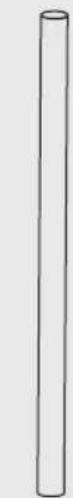
Pole (x1)

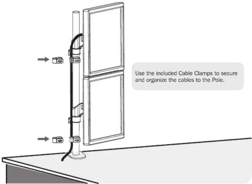
Cable Clamp (x2)
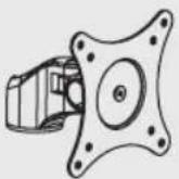
Mount Assembly with VESA Plate (x2)
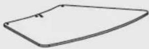
Base (x1)
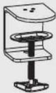
Clamp (x1)
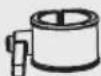
Locating Ring (x2)

Top Cap (x1)

3 mm Hex Key (x1)
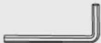
4 mm Hex Key (x1)
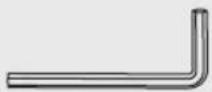
5 mm Hex Key (x1)
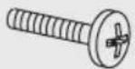
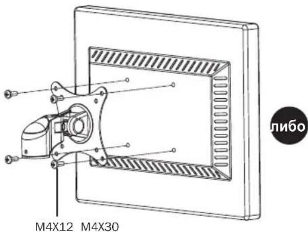
M4X12 (x8)
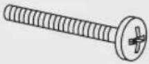
M4X30 (x8)

M6X15 (x3)
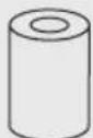
Spacer (x8)
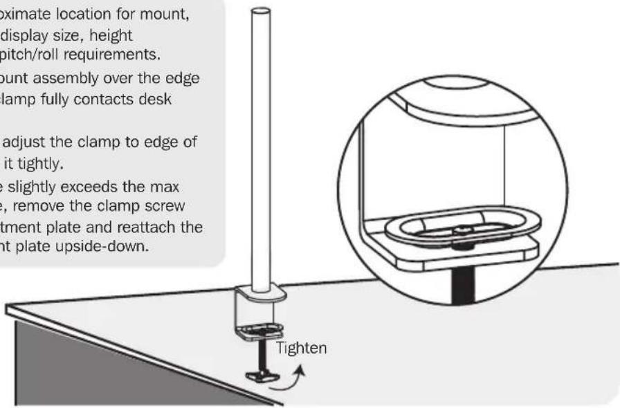
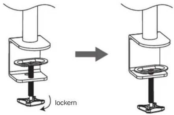
1a. Desk Clamp Mounting
- Determine approximate location for mount, keeping in mind display size, height adjustment and pitch/roll requirements.
- Slip the desk mount assembly over the edge of desk so that clamp fully contacts desk edge.
- Turn the knob to adjust the clamp to edge of desk and secure it tightly.
- If desk edge size slightly exceeds the max desktop distance, remove the clamp screw and clamp adjustment plate and reattach the clamp-adjustment plate upside-down.
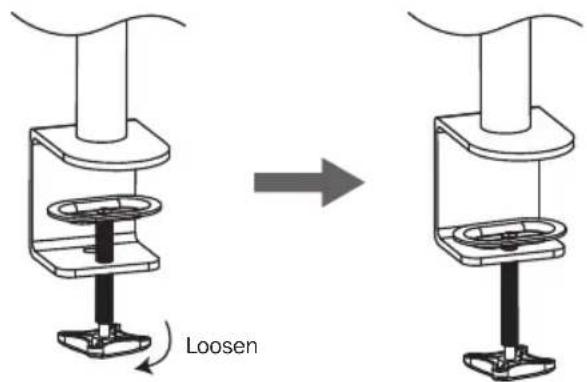
1b. Desktop Mounting
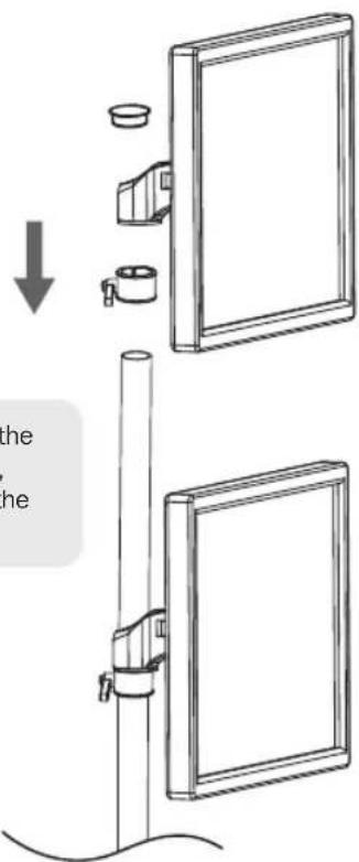
2. Installing the Locating Ring
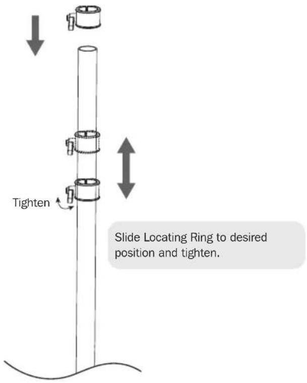
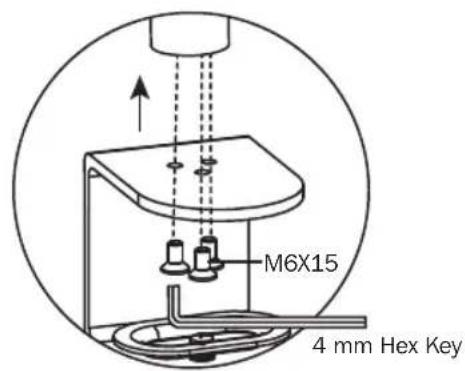
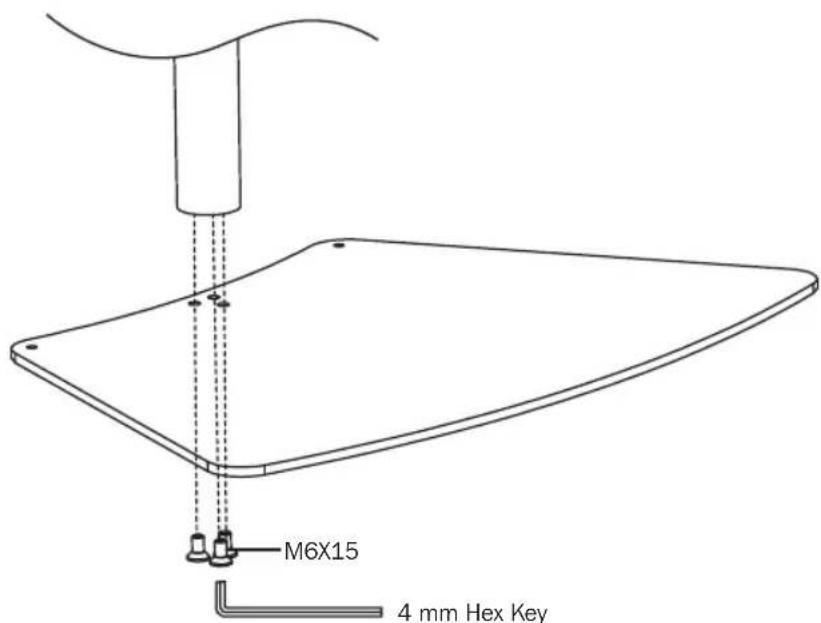
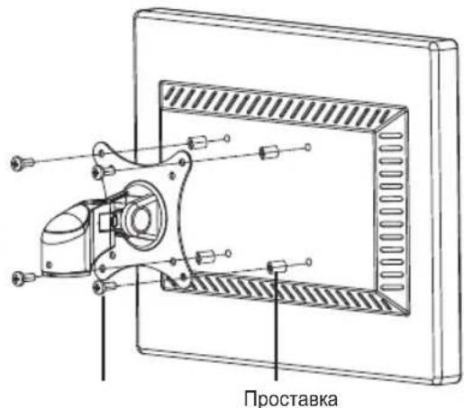
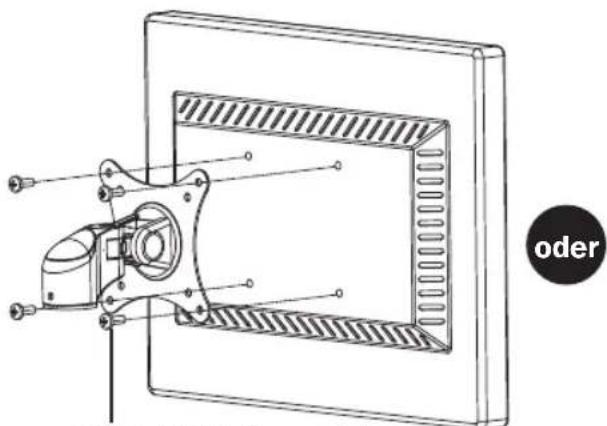
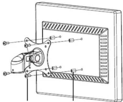
3. Attaching VESA Plate to Display
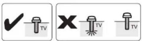
Lift the display and align the rear mounting holes with the mount assembly's VESA plate.
Attach the display to the VESA plate with the appropriate included screws.

Do not over-tighten screws.
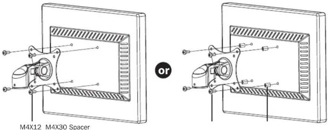
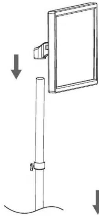
4. Installing the Display
natural_image
Diagram showing a vertical pole with a mounted rectangular panel and a downward arrow indicating force or movement (no text or symbols present)Using an assistant or mechanical lifting equipment, lift the display with attached Mount Assembly and slide it down onto the pole until it touches the Locating Ring. Make sure the display is safely secured before releasing.
Repeat Steps 2 and 3 to install the second display. When completed, insert the Top Cap on the top of the Pole.

WARNING: Always ensure both monitors face forward. Turning the monitors to face backward may cause the unit to tip over.
5. Tension Adjustment
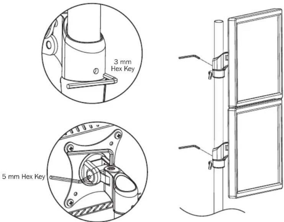
Use the appropriate Hex Keys to adjust the swivel. Turn clockwise to increase tension or counter-clockwise to reduce tension.
6. Cable Management
7. Adjustment
To adjust the desired location or tilt, use the appropriate Hex Key to adjust. Turn clockwise to tighten or counterclockwise to loosen.
Maintenance
- Check that the bracket is secure and safe to use at regular intervals (at least every three months).
- Please visit www.triplite.com/support if you have any questions.


1111 W. 35th Street, Chicago, IL 60609 USA • www.tripplite.com/support
natural_image
Technical line drawing of a vertical mechanical device with mounting base and two side-mounted sensors (no text or symbols)English 1 • Français 17 • Русский 25 • Deutsch 33

1111 W. 35th Street, Chicago, IL 60609 USA • www.tripplite.com/support
natural_image
Simple line drawing of a vertical cylindrical object (no text or symbols)Poste (x1)

natural_image
Technical line drawing of two views of a computer monitor with internal components and connectors (no text or symbols)M4X12 M4X30 Espaciador
natural_image
Diagram showing a vertical pole with a mounted rectangular panel and a downward arrow indicating force or change (no text or symbols present)
1111 W. 35th Street, Chicago, IL 60609 USA • www.tripplite.com/support
natural_image
Technical line drawing of a mechanical device with a vertical pole, two mounting flanges, and a base mount (no text or symbols)English 1 • Español 9 • Русский 25 • Deutsch 33

MISE EN GARDE : NE PAS EXCÉDER LA CAPACITÉ PONDÉRALE MAXIMUM INDI-QUÉE. DES BLESSURES GRAVES OU DES DOMMAGES MATÉRIELS RISQUENT DE SE PRODUIRE!

75 x 75 100 x 100


1111 W. 35th Street, Chicago, IL 60609 USA • www.tripplite.com/support
natural_image
Technical line drawing of two views of a computer monitor with internal components and connectors (no text or symbols)M4X12 M4X30 Entretoise
natural_image
Diagram showing a vertical pole with a mounted rectangular panel and a downward arrow indicating force or change (no text or symbols present)natural_image
Diagram showing two mechanical components with a downward arrow indicating assembly or alignment (no text or symbols present)1111 W. 35th Street, Chicago, IL 60609 USA • www.tripplite.com/support
natural_image
Technical line drawing of a vertical mechanical device with mounting base and two side-mounted arms (no text or symbols)English 1 • Español 9 • Français 17 • Deutsch 33

1111 W. 35th Street, Chicago, IL 60609 USA • www.tripplite.com/support
natural_image
Diagram showing a vertical pole with a mounted rectangular panel and a downward arrow indicating force or change (no text or symbols present)1111 W. 35th Street, Chicago, IL 60609 USA • www.tripplite.com/support
Benutzerhandbuch
natural_image
Technical line drawing of a mechanical device with a vertical pole and two mounting flanges (no text or symbols)English 1 • Español 9 • Français 17 • Русский 25

1111 W. 35th Street, Chicago, IL 60609 USA • www.tripplite.com/support
M4X12 M4X30 Distanzscheibe
natural_image
Technical line drawing of a mechanical assembly with no visible text or symbolsnatural_image
Diagram showing a vertical pole with a mounted rectangular panel and a downward arrow indicating force or change (no text or symbols present)Manufacturing Excellence
1111 W. 35th Street, Chicago, IL 60609 USA • www.tripplite.com/support
- Dual Vertical Flat Screen Desk or Clamp Mount
- PROTECT YOUR INVESTMENT!
- WARNING
- Warranty and Product Registration
- 5-Year Limited Warranty
- PRODUCT REGISTRATION
- Component Checklist
- 1a. Desk Clamp Mounting
- 1b. Desktop Mounting
- Installing the Locating Ring
- Attaching VESA Plate to Display
- Installing the Display
- Tension Adjustment
- Cable Management
- Adjustment
- Maintenance
- Benutzerhandbuch
Brand : Tripp Lite
Model : DDR1527SDC
Category : Monitor stand