SRXCOOL33K - Air Conditioning Tripp Lite - Free user manual and instructions
Find the device manual for free SRXCOOL33K Tripp Lite in PDF.
| Product Type | Standalone cooling for computer room / server (42U tower) |
| Brand | Tripp Lite |
| Model | SRXCOOL33K |
| Dimensions (H x W x D) | 199.3 x 60.3 x 122 cm (78.5 x 23.75 x 48 in) |
| Weight | 317.5 kg (700 lb) |
| Power Supply | 208-240 V, 50/60 Hz, hardwired (user-supplied removable IEC 309 32 A cord) |
| Cooling Capacity | 33,000 BTU |
| Compressor | Variable speed DC with inverter, electronic expansion valve (EEV) |
| Refrigerant | R410A, 4 kg (8.81 lb) |
| Evaporator Airflow | 1000 - 1230 CFM |
| Condenser Airflow | 945 - 1012 CFM |
| Noise Level | < 75 dBA |
| Control Screen | Multi-line LCD with menus, navigation buttons and status indicator |
| Remote Monitoring | SNMP, Web, Telnet, Modbus (requires SNMPWEBCARD sold separately) |
| Main Features | Precision cooling, soft start, condensate atomization (no drain needed), room or cold/hot aisle mode |
| Maintenance and Cleaning | Clean or replace air filter monthly; clean coils and drain pan; use non-toxic, non-corrosive products |
| Safety | Mandatory grounding; do not use with panels removed; disconnect before maintenance; do not block air outlets; use by qualified personnel |
| Spare Parts and Repairability | Air filters, fans, compressor, water pump, electronic boards; repair by Tripp Lite authorized technician |
| Warranty | 1 year limited (parts only); extensions available (WEXT3-SRCOOL33K, WEXT5-SRCOOL33K) |
Frequently Asked Questions - SRXCOOL33K Tripp Lite
User questions about SRXCOOL33K Tripp Lite
0 question about this device. Answer the ones you know or ask your own.
Ask a new question about this device
Download the instructions for your Air Conditioning in PDF format for free! Find your manual SRXCOOL33K - Tripp Lite and take your electronic device back in hand. On this page are published all the documents necessary for the use of your device. SRXCOOL33K by Tripp Lite.
USER MANUAL SRXCOOL33K Tripp Lite
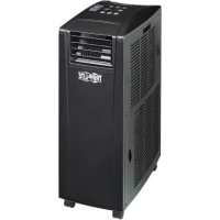
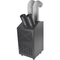
Self-Contained Air Conditioning Unit
Models: SRCOOL33K, SRXCOOL33K
natural_image
Line drawing of a multi-tiered industrial air conditioning unit with ventilation grilles and mounting base (no text or symbols)Table of Contents
- Introduction 2
- Important Safety Instructions 2
- Features 3
- Specifications 4
- Operation 5
-
Troubleshooting 11
-
Preventive Maintenance 12
- Storage and Service 14
- Warranty & Warranty Registration 15
Español 17
Francais 33
Русский 49


1111 W. 35th Street, Chicago, IL 60609 USA • www.tripplite.com/support
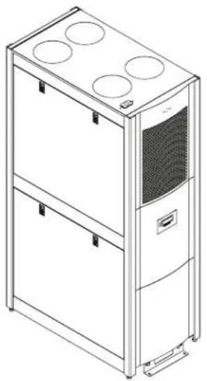
1. Introduction
Tripp Lite's SRCOOL33K/SRXCOOL33K is a self-contained air conditioning unit housed in a standard 42U enclosure. The SRCOOL33K/SRXCOOL33K is optimized for general computer room cooling or supplemental cooling in a large server room. It features an inverter-driven DC (direct current) variable-speed compressor that delivers high-efficiency precision cooling. This helps maintain set temperature without the traditional method of wasteful On/Off cycling.
A menu-driven, multi-line LCD screen provides on-site monitoring and control of various operating conditions. These operational conditions can also be monitored and controlled remotely via SNMP, Web, telnet or Modbus.
2. Important Safety Instructions

SAVE THESE INSTRUCTIONS
All sections of this owner's manual contain instructions and warnings that must be followed during the operation of the products described in this manual. Read ALL instructions before attempting to operate these products. Failure to comply may invalidate the warranty and cause serious property damage and/or personal injury.
- Prior to use, the individual user must determine whether this device is suitable, adequate or safe for the use intended. Since individual applications are subject to great variation, the manufacturer makes no representation or warranty as to the suitability or fitness of this device for any specific application.
- The cooling unit operates under pressure. Observe proper safety precautions when operating or servicing the unit.
- Do not operate the unit with any cover, guard, door, or panel removed unless the instructions indicate otherwise.
- Do not run cabling or service utilities in front of the fan outlets.
- Connect the unit directly to a grounded AC power outlet. Failure to do so may cause electric shock or fire. Note: If the unit is hardwired, the user should ground it according to local regulations.
- The power supply for the unit must be rated as specified on the unit's nameplate.
- Never modify the unit's plug or use an adapter if the unit is equipped with an input power cord.
- Comply with all local and national wiring and safety regulations applicable where the unit will be installed, e.g. The National Electric Code (NEC) in the United States.
- On models with an input cord, never use the cord as a means to turn the unit on or off. A serious electric shock may occur. Always use the control panel to power the unit on or off.
- Always turn the unit off and disconnect it from the mains input source by unplugging the unit or opening the mains circuit breaker before performing maintenance.
• Before connecting the unit to a dedicated drainage system, turn it off and unplug it. - Maintenance should be performed by trained personnel only.
- Do not use thinners, alcohol, detergents or abrasive brushes to clean the unit's cabinet. These may damage the cabinet.
- Do not operate the unit without the air filter. This may cause dust accumulation that can damage the unit.
- Do not attempt to operate the unit in any room with inadequate air circulation. There must be adequate airflow to the condenser.
- Do not place objects on top of the unit.
• Prior to operation, ensure that:
- The unit has been properly installed in accordance with the procedures detailed in the Installation Manual
• There is no evidence of damage to the unit
• The unit is level and stabilized
- The clearance around the cooling unit complies with local and national codes and regulations as well as the installation manual

- Warning! Do not use this equipment in the presence of a flammable anesthetic mixture with air, oxygen or nitrous oxide.
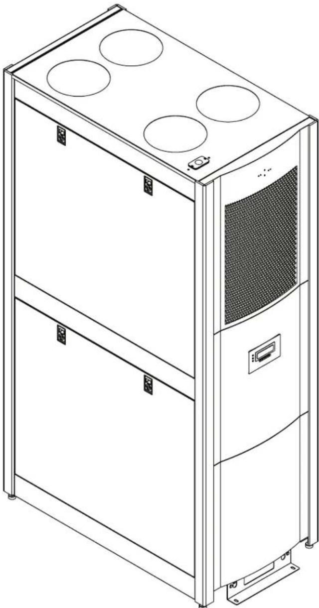
3. Features
natural_image
Line drawing of a multi-tiered industrial air conditioning unit with mounting holes and control panels (no text or symbols)• 33,000 BTU of cooling power
- Variable-speed, DC-inverter-driven compressor and microprocessor-controlled electronic expansion valve (EEV) enable precision cooling adjustments
- Soft-start feature limits inrush current to prevent introduction of line noise, voltage disruptions and potential circuit overloads
- Self-contained, zero-maintenance unit atomizes condensate and expels it through the exhaust air stream—no floor drain, water collection tank, external condenser, refrigerant piping, ductwork or plumbing required when used in typical conditions
- Convenient LCD control panel and network interface enable local and remote monitoring and control of temperature, fan speed, alarms and logging via front-panel buttons, SNMP, Web, telnet or Modbus
- Row-based airflow path maximizes hot-aisle/cold-aisle efficiency and cooling predictability by supplying cold intake air high in the cold aisle and removing hot equipment exhaust air low from the hot aisle
• Eco-friendly R410a refrigerant meets environmental standards worldwide
• Nominal 208-240V AC Input, 50/60 Hz frequency compatibility
4. Specifications
| Specification SRCOOL33K SRXCOOL33K | ||
| Input | ||
| Nominal input voltage 208-240V; 50/60Hz 208-240V; 50/60Hz | ||
| Input connection type L6-30P (Hardwire Optional) Hardwire (User supplied IEC 309 32 amp | cord set, optional) | |
| Input cord length (ft/m) 10 ft / 3.05 m 10 ft / 3.05 m | ||
| LEDs, Alarms and Switches | ||
| Controls Multi-line LCD control panel Multi-line LCD control panel | ||
| Physical | ||
| Unit weight (lb/kg) 700 / 317.5 700 / 317.5 | ||
| Unit dimensions (HWD/in) 78.5 x 23.75 x 48 | 78.5 x 23.75 x 48 | |
| Unit dimensions (HWD/cm) 199.3 x 60.3 x 122 | 199.3 x 60.3 x 122 | |
| Material of construction | Steel and aluminum | Steel and aluminum |
| Color | Black | Black |
| Form factor | Tower (42U equivalent) | Tower (42U equivalent) |
| Environmental | ||
| Cooling capacity (BTU) | 33,000 | 33,000 |
| Features | ||
| Dehumidifier capacity | 0.85 gal/hr | 0.85 gal/hr |
| Compressor type | DC, inverter-driven, variable speed | DC, inverter-driven, variable speed |
| Refrigerant (type/capacity) | R410a / 4kg (8.81 lbs.) | R410a / 4kg (8.81 lbs.) |
| Air flow | Evaporator: 1000-1230 CFM Condenser: 945-1012 CFM | Evaporator: 1000-1230 CFM Condenser: 945-1012 CFM |
| Amp draw | Variable (0-24 L6-30P; 0-30 Hardwire) | Variable (0-24 L6-30P; 0-30 Hardwire) |
| Sound level (noise) | <75dBA | <75dBA |
| Air tube length (in/cm) | 71/180 | 71/180 |
| Warranty | ||
| Standard limited warranty | 1 year (US/Canada only) | 1 year (Parts only) |
| Optional coverage (extensions of standard warranty period) | 2-year (WEXT3-SRCOOL33K); 4-year (WEXT5-SRCOOL33K) | Not available |
Regulatory Notice: This unit carries less than 22 lbs. of refrigerant and complies with all Department of Transportation shipping regulations. It is exempt from any additional requirements. The user does not have to make any extra accommodations to transport the unit.
5. Operation

Caution: Before attempting to operate the SRCOOL33K/SRXCOOL33K, ensure that it has been properly installed in accordance with the Installation Manual, including stabilization and sufficient clearance around the unit.
Tip Warning! If the unit has been tilted more than 15^ during shipping, unpacking or installation, allow unit to stand for 24 hours before turning on. Do not operate if there is visible internal or external damage.
5.1 Cooling Methods
The main function of the SRCOOL33K/SRXCOOL33K is to remove waste heat and return treated air to the room at the required temperature. The specific cooling method used is determined by the configuration of the rack enclosures in the room. The unit continuously varies the cooling output to maintain a set temperature at the return of the unit. The cooling output is varied by constantly adjusting the speed of the fans and the compressor. If desired, the fan speed may be set to a constant value by the user. Note: Setting a lower fan speed may limit the unit's capacity.
The unit uses the setpoint entered by the user to control the fan speed. This variable should be set based on the installation configuration.
Configurations
Room Cooling Mode: When the unit is installed stand-alone in a server room acting as a CRAC unit, the setpoint should be set to the desired room temperature.
In-Row/Hotspot Mode: When the unit is installed in a hot aisle/cold aisle configuration, the setpoint should be set to the desired cold aisle temperature plus the expected temperature rise across the problem rack ( 10^ ; 50^ ).
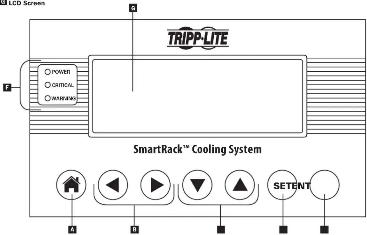
5.2 LCD Control Panel
A Button leads directly to the HOME menu/Cancels input
B Left/Right navigation arrows/Input adjustment buttons
C Up/Down navigation arrows/ Input adjustment buttons
D SET button scrolls through the input fields
E ENT button confirms new value
F Status LEDs
G LCD Screen
flowchart
graph TD
    A["LCD Screen"] --> B["TRIPP-LITE"]
    B --> C["Power"]
    B --> D["Critical"]
    B --> E["Warning"]
    F["SmartRack™ Cooling System"] --> G["A"]
    F --> H["B"]
    F --> I["SetENT"]
    style A fill:#f9f,stroke:#333
    style B fill:#ccf,stroke:#333
    style C fill:#cfc,stroke:#333
    style D fill:#fcc,stroke:#333
    style E fill:#cff,stroke:#333
    style F fill:#ffc,stroke:#333
    style G fill:#fcf,stroke:#333
    style H fill:#cff,stroke:#333
    style I fill:#fcf,stroke:#333
5. Operation
5.3 Initial Operation
To Power the Unit On
1 Make sure that the SRCOOL33K/SRXCOOL33K is properly connected to the AC input source according to the Installation Manual.
To Change Initial Cooling Temperature
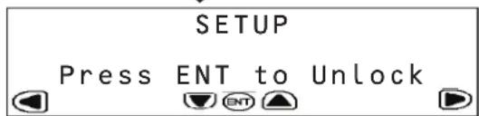
1 Scroll right to the SETUP Menu.
2 Press ENT to access the password screen.
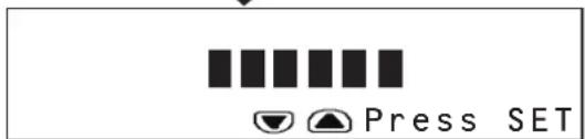
3 Press SET to select Open Password option then press ENT to access the sub-menu.
4 The default password is 000000 and is already listed on the screen. Press SET to enter the password and press ENT to confirm.
5 The display will read SYSTEM UNLOCKED. The system will lock itself automatically after 3 minutes of inactivity.
6 Press the HOME button to return to the home screen.
7 Scroll right to the SETUP Menu.
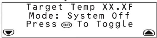
8 Scroll down to the first sub-menu of the SETUP Menu.
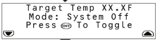
9 Enter the desired Target Temperature using SET to select the temperature field and the up/down arrow keys to modify the numerical value. Press ENT to confirm new temperature.
10 Pressing the ENT key will now toggle the Cooling Mode ON and OFF.
Note: The unit has a factory default cooling temperature of 25^ C ( 77^ F).
5.4 LCD Control Panel Menu Map
The SRCOOL33K/SRXCOOL33K is configured and controlled via an interactive, menu-based LCD Control Panel. Navigate from menu to menu by touching the left and right arrows. There are five menus: STATUS, SETUP, LOGS, INFO and HELP. When the SRCOOL33K/SRXCOOL33K is initialized, the HOME screen appears. The HOME and ALARMS screens are menus that alert you to the status of the unit. To navigate within a menu, use the up and down arrows.
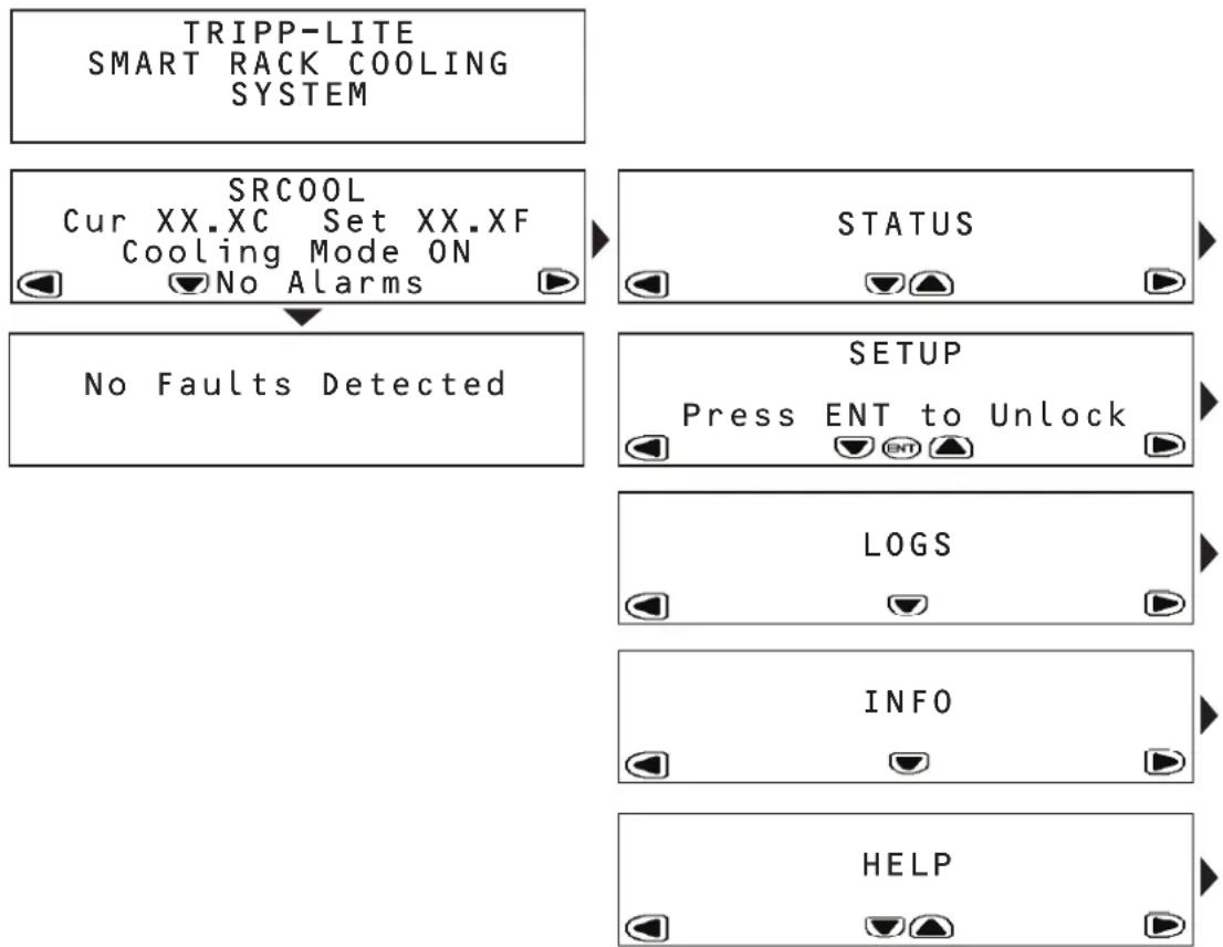
flowchart
graph TD
    A["TRIPP-LITE SMART RACK COOLING SYSTEM"] --> B["SRCOOL Cur XX.XC Set XX.XF Cooling Mode ON No Alarms"]
    B --> C{No Faults Detected}
    C --> D["STATUS"]
    C --> E["SETUP Press ENT to Unlock"]
    E --> F["LOGS"]
    E --> G["INFO"]
    E --> H["HELP"]
5. Operation
5.5 HOME Menu and Alarms
The HOME menu indicates if the unit is operational, the current operating conditions and if there are any active alarms.
The HOME screen displays the current temperature and the set temperature the unit is trying to achieve.
If an alarm condition is indicated, details can be viewed by touching the down arrow. The SRCOOL33K/SRXCOOL33K can sense and display the following alarm conditions. (W) indicates a warning/advisory alarm; (!) indicates a fault that requires immediate attention.
Warnings
| Alarm Conditions Display User A | Action | |
| Supply air sensor failure 1 (W)SUP AIR SEN FAIL Call Tripp Lite for service. | ||
| Condenser in sensor failure 3 (W)COND IN SEN FAIL Call Tripp Lite for service. | ||
| Condenser out sensor failure 4 (W)OND OUT SEN FAIL Call Tripp Lite for service. | ||
| Evaporator temperature probe fault 6 (W)EVAP TEMP FAIL Call Tripp Lite for service. | ||
| Air filter blockage/clog 9 (W)AIR FILTER CLOG Check the air filter for any blockage. Replace the air filter.Call Tripp Lite for service if error remains. | ||
| Air filter requires replacement | 10 (W)AF HOURS EXCEEDED | Check the air filter for any blockage. Replace the air filter. Reset the Air Filter Hours menu. Call Tripp Lite for service if error remains. |
| Excessive return temperature 20 (W)RETURN AIR HIGH The alarm set point is too low and the unit cannot keep up with the heat load. Reduce the heat load. If error remains, call Tripp Lite for service. | ||
| Excessive supply temperature | 21 (W)SUPPLY AIR HIGH | The alarm set point is too low and the unit cannot keep up with the heat load. Reduce the heat load. If error remains, call Tripp Lite for service. |
| Low suction pressure | 28 (W)LOW SUCT PRESS | Call Tripp Lite for service. |
| Water leak | 33 (W)WATER LEAK | Identify the water leak and correct it. |
Critical Faults
| Alarm Conditions Display User Action | ||
| Return air sensor failure 2 (!)RET AIR | SEN FAIL Call Tripp Lite for service. | |
| Suction temperature sensor fault 5 ( ) | SUCT TEMP SENSOR Call Tripp Lite for service. | |
| High discharge pressure | 7 (!) HI DISCH PRESS | Check for any blockage of the condenser. Call Tripp Lite for service. |
| Suction pressure failure | 8 (!)SUCT PRESS FAIL | Call Tripp Lite for service. |
| Communications between controller and compressor have failed | 12 (!)INVERTER COM FAIL Call Tripp Lite for service. | |
| Remote shutdown has been closed | 13 (!)REMOTE SHUT DOWN | Reset the EPO or remote contact. If the error persists, call Tripp Lite for service. |
| Water pump failure | 14 (!)H2O PUMP FAIL | Check for any water in the upper tray. If the tray is full, pump the water out of the unit using the supplied hose and adjust any humidification systems in use. If the upper tray is dry, call Tripp Lite for service. |
| Condenser failure | 18 (!)COND FAILURE | Check for any blockage of the condenser. Call Tripp Lite for service. |
| Evaporator failure | 22 (!)EVAP FAILURE | Check the air filter and evaporator for any blockage. Call Tripp Lite for service. |
| Evaporator icing | 23 (!)EVAP ICE UP | Check the air filter and evaporator for any blockage. Call Tripp Lite for service. |
| Excessive discharge pressure | 24 (!)HIGH DISCH PRESS | Check for any blockage of the condenser. Call Tripp Lite for service. |
| Discharge switch failure | 25 (!)DISCH SWITCH FAIL | Call Tripp Lite for service. |
| Excessive system pressure | 26 (!)HIGH SYSTEM PRESS | Check for any blockage of the condenser. Call Tripp Lite for service. |
| System has run out of refrigerant | 27 (!)LOW CHARGE | Call Tripp Lite for service. |
| Persistent low suction pressure | 29 (!)LOW SUCT PRESS | Call Tripp Lite for service. |
| High and low pressures have not returned to nominal | 30 (!)LINE IMBALANCE | Call Tripp Lite for service. |
| Compressor failure | 31 (!)COMPRESSOR FAIL | Call Tripp Lite for service. |
| Fan failure | 34 (!)FAN FAIL | Call Tripp Lite for service. |
5. Operation
5.6 STATUS Menu

flowchart
graph TD
    A["STATUS"] --> B["Operating Mode ON\nCooling Output XX.XkW\nReturn Temp XX.XF\nSupply Temp XX.XF"]
    B --> C["Remote Temp XX.XF\nCond. Inlet Temp XX.XF\nCond.Outlet Temp XX.XF"]
    C --> D["Suct. Pressure XX.XMpa\nDisch. Pressure XX.XMpa\nSuct. Temp XX.XF\nEvap. Temp XX.XF"]
    D --> E["Evap Fan Speed XX\nCond Fan Speed XX\nComp. Freq XXHz\nEEV Step XXXX"]
    E --> F["Comp Current XX.XA\nFan Current XX.XA\nTotal Current XX.XA"]
    F --> G["Run Hours\nAir Filter XXXXHr\nEvap Fan XXXXDay\nCond Fan XXXXDaj"]
    G --> H["Compressor XXXXDay\nCondensate Pump XXXXDay\nAtomizer XXXXDaj"]
The STATUS menu provides information on current operating conditions. Touch the down arrow to access sub-menus.
The first sub-menu provides:
- Operating mode
• Cooling output (estimated in kW)
• Temperature of the air entering the SRCOOL33K/SRXC00L33K
• Temperature of the air leaving the SRC00L33K/SRXC00L33K
The second sub-menu provides:
• Temperature at the remote sensor
• Temperature of the air entering the condenser
• Temperature of the air leaving the condenser
The third sub-menu provides:
• Refrigerant pressure at the compressor inlet
• Discharge pressure at the compressor outlet
• Temperature of the refrigerant entering the compressor
• Temperature at the evaporator
The fourth sub-menu provides:
• Speed of the fans that regulate evaporator air flow
• Speed of the fans that regulate condenser air flow
• Frequency of compressor operation (in Hz)
• Electronic expansion valve position
The fifth sub-menu provides:
• Current the compressor is drawing
• Current the fans are drawing
• Total current for the unit
The sixth and seventh sub-menus provide the time the following components have been in use:
- Air filter
- Evaporator fan
- Condenser fan
- Compressor
- Condensate pump
- Atomizer
5. Operation
5.7 SETUP Menu
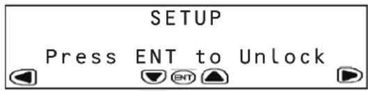
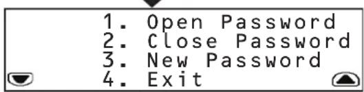

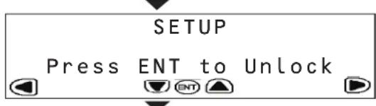
The SETUP menu enables you to set the operating parameters of the SRCOOL33K/SRXCOOL33K. To access sub-menus, you must first unlock the menu by providing the assigned password. When at the initial SETUP menu, press ENT to bring up the password menu.
In the password menu, you have to option to:
- Enter the password to unlock the SETUP system
- Close the password and lock the system
• Create a new password
To create a new password:
- Unlock the SETUP system with the current password. The default password is 000000.
- Scroll back to the password menu and use SET to scroll to 'New Password'.
- Press SET to access the numerical field and use the up/down arrows to enter the new password. Press ENT.
- At the confirmation menu, re-enter the new password and press ENT.
- The unit will notify you if the password has been successfully changed.
- Exit the SETUP menu
Note: Passwords can be up to six characters in length and must be made up of numeric values.
The first sub-menu allows you to input:
• Target temperature of the room
• System mode (On or Off)
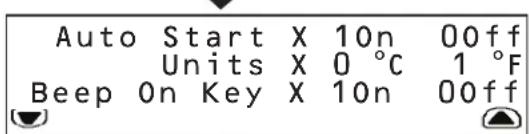
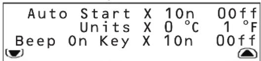
The second sub-menu allows you to input:
• Whether the unit should start automatically when plugged in
• Units of display (SI or English)
- Beeping preference when keys are pressed
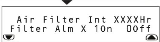
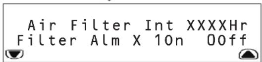
The third sub-menu allows you to input:
• Hours until the air filter must be replaced
- Enable or disable air filter replacement alarm
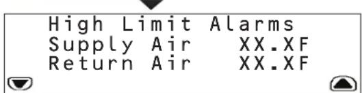
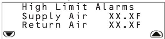
The fourth sub-menu allows you to set high-limit alarms for:
• Temperature leaving the SRCOOL33K/SRXC00L33K
• Temperature entering the SRCOOL33K/SRXC00L33K
Note: The unit alerts you when either temperature exceeds your set value.
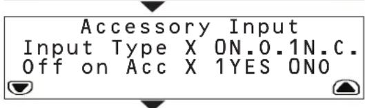
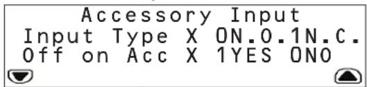
The fifth sub-menu allows you to input:
- The normal state of the accessory input. (N.O. is defined as Normally Open while N.C. is defined as Normally Closed)
• Whether the unit shuts down if the input state changes
Note: The unit will always send a warning when the sensor changes.
The SRCOOL33K/SRXCOOL33K comes with an input contact that can be user-defined. The contact monitors a sensor and responds to any changes in the state of the sensor.
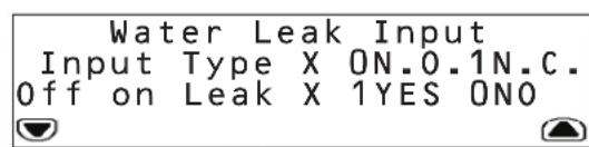
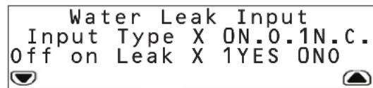
The sixth sub-menu allows you to toggle:
• The normal state of the water leak sensor (Open or Closed)
• Whether the unit shuts down if a leak is detected
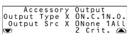
The SRCOOL33K/SRXC00L33K comes with an output contact that can be user-defined. The contact monitors a sensor and responds to any changes in the state of the sensor.
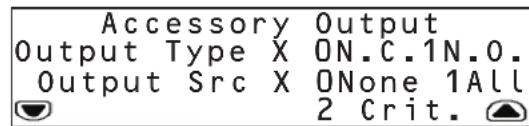
The seventh sub-menu allows you to toggle:
• The normal state of the accessory output (Open or Closed)
- What type of alarm causes the output to change from normal (None, All or Critical)
5. Operation
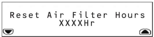

The eighth sub-menu allows you to reset the number of hours the current air filters has been in use.
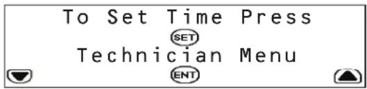
The ninth sub-menu allows you to set the time and access the Technician menu.
The Technician menu is used for changing the electrical current settings when using the unit in a hardwire configuration.

WARNING! Do not change this setting on the SRCOOL33K when using the supplied L6-30P input cord. Do not place setting at any other value other than 24.0 Amps (with Input Cord) or 30.0 Amps (Hardwire). Do not change this setting on the SRXCOOL33K.
Please consult the Installation Manual for further information.
5.8 LOGS and INFO Menus
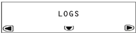
The LOGS menu provides access to the Event Log page. All alarms are entered into the Event log, tagged with a time/date stamp.
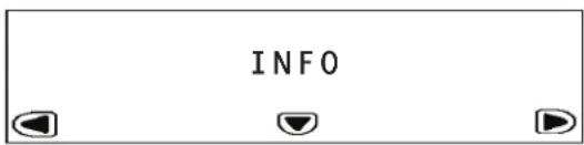
The INFO Menu provides access to the Information Page. This page displays the Model Name, Serial Number, Location, Unit Name and other information about the SRCOOL33K/SRXCOOL33K.
5.9 HELP Menu
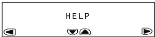
The HELP Menu provides an on-screen tutorial showing how to navigate through the menus and sub-menus.
5.10 Remote Monitoring and Control
The SRCOOL33K/SRXC00L33K can be remotely monitored and controlled via SNMP, Web, telnet or Modbus. Remote monitoring and control requires a network card such as Tripp Lite's SNMPWEBCARD (sold separately) in order to turn the SRCOOL33K/SRXC00L33K into a network-managed device. Please consult the SRCOOL33K/SRXC00L33K installation manual and web card documentation for further information on installing and configuring your network card. Update to the latest version of the SNMPWEBCARD firmware. It can be downloaded from triplite.com.
6. Troubleshooting
Locate the problem and review possible solutions in the following table. If the problem persists, visit www.tripplite.com/support to obtain service.
| Problem Possible | Cause Possible Solution | |
| Fan fails to start. Cooling unit | shutdown due to an external command. | Disconnect communications cable and restart unit. |
| Faulty fan. Replace the fan. | ||
| Cooling unit cannot achieve setpoint. | Dirty filter. Clean filter. | |
| Dirty coil. Clean coil. | ||
| Heat load is too far away. Relocate | cooling unit. | |
| Improper fan speed. Fan speed set | to Low. Set fan speed to Auto or increase fan speed. | |
| Excess water in or around the unit. | Room humidity too high. Add drain line. Adjust set point on humidifying equipment. Improve room sealing. | |
| Dirty filter. Clean filter. | ||
| Dirty coil. Clean coil. | ||
| Cooling unit noise level is excessive. | Improper fan speed. Select lower fan speed. | |
| Water around cooling unit. Con | condensate drain hose not connected or not properly routed. | Verify proper connection of condensate drain hose, proper routing to pump and proper routing outside of cooling unit. |
| Leak in drain system. Locate and repair leak. | ||
| Cooling unit not properly leveled. Adjust cooling unit's leveling feet. | ||
| Piping insulation damaged. Locate damage area and repair insulation. | ||
| Cooling unit operates but LCD panel does not function. | Local display not properly connected. | Verify proper connection of local display cable. |
7. Preventive Maintenance
Note: The following pages can be photocopied for use during scheduled maintenance. Tripp Lite recommends that completed maintenance forms be saved for future reference.
Self-Contained Air Conditioning Unit Preventive Maintenance
Tripp Lite SRCOOL33K/SRXCOOL33K MONTHLY MAINTENANCE CHECKLIST
Prepared By: Date:
Model Number Serial Number
General Inspection
Location of cooling unit
Temperature setpoint
Room temperature/humidity near the return of the cooling unit:
Temperature ____ Humidity ____
Is the unit maintaining the temperature setpoint? Yes □ No □
Is there visible damage to the cooling unit, e.g. dents or scratches? Yes □ (Specify) No □
Are there indications of environmental damage (dirt, dust, debris, liquid stains) around the unit installation area?
Yes □ (Specify) No □
Previous month's alarm history:
Cleanliness Inspection
☐ Check the condition of return air filters. Change if necessary.
Mechanical/Electrical Inspection

Caution!
Turn off the cooling unit and disconnect all power sources before performing mechanical and electrical checks.
☐ Check the fan. All components should be moving freely, with no indication of binding or damage.
☐ Verify that the condensate line is flowing freely.
☐ Inspect the power cord and plug for damage.
7. Preventive Maintenance
Tripp Lite SRCOOL33K/SRXCOOL33K QUARTERLY MAINTENANCE CHECKLIST
Prepared By: ____ Date: ____
Model Number Serial Number
Perform all Monthly Maintenance Checklist tasks PLUS the following tasks:
Mechanical/Electrical Inspection

Caution!
Turn off the cooling unit and disconnect all power sources before performing mechanical and electrical checks.
☐ Inspect fan hardware and tighten if necessary.
□ Clean or replace filters.
□ Clean condensate pans.
□ Clean the condensate drain line.
☐ Remove any debris from condensate floats.
□ Clean dust from door perforations.
□ Clean dust from fan bezels.
☐ Verify proper functioning of the cooling operation mode.
☐ Treat the drain pan with a plating product like Virginia Pan Tabs. Verify that the product you use is non-toxic, non-corrosive and will not leave deposits that could damage the unit and drain pan.
Note: Treating the drain pain helps eliminate problems such as odor, overflow and water damage by preventing plugged drain lines and openings.
Cleanliness Inspection
☐ Check the condition of the drain pan and accumulation of debris in the pan. Clean as required.
Tripp Lite SRCOOL33K/SRXCOOL33K SEMIANNUAL MAINTENANCE CHECKLIST
Prepared By: Date:
Model Number Serial Number
Perform all Monthly Maintenance Checklist tasks PLUS the following task:
☐ Inspect the evaporator and condenser coils and clean if required.
8. Storage and Service
Storage
Before storing the unit, confirm that all ducts and vents are secured or removed and properly stored. Also confirm that the unit is drained of condensation.
Service
Your Tripp Lite product is covered by the warranty described in this manual. A variety of Extended Warranty and On-Site Service Programs are also available from Tripp Lite. For more information on service, visit www.triplite.com/support. Before returning your product for service, follow these steps:
- Review the installation and operation procedures in this manual to insure that the service problem does not originate from a misreading of the instructions.
- If the problem continues, do not contact or return the product to the dealer. Instead, visit www.tripplite.com/support.
- If the problem requires service, visit www.triplite.com/support and click the Product Returns link. From here you can request a Returned Material Authorization (RMA) number, which is required for service. This simple on-line form will ask for your unit's model and serial numbers, along with other general purchaser information. The RMA number, along with shipping instructions will be emailed to you. Any damages (direct, indirect, special or consequential) to the product incurred during shipment to Tripp Lite or an authorized Tripp Lite service center is not covered under warranty. Products shipped to Tripp Lite or an authorized Tripp Lite service center must have transportation charges prepaid. Mark the RMA number on the outside of the package. If the product is within its warranty period, enclose a copy of your sales receipt. Return the product for service using an insured carrier to the address given to you when you request the RMA.
9. Warranty and Warranty Registration
1-YEAR LIMITED WARRANTY
Seller warrants this product, if used in accordance with all applicable instructions, to be free from original defects in material and workmanship for a period of 1 year from the date of initial purchase. If the product should prove defective in material or workmanship within that period, Seller will repair or replace the product, in its sole discretion. Service under this Warranty can only be obtained by your delivering or shipping the product (with all shipping or delivery charges prepaid) to: Tripp Lite, 1111 W. 35th Street, Chicago, IL 60609 USA. Seller will pay return shipping charges.
THIS WARRANTY DOES NOT APPLY TO NORMAL WEAR OR TO DAMAGE RESULTING FROM ACCIDENT, MISUSE, ABUSE OR NEGLECT. SELLER MAKES NO EXPRESS WARRANTIES OTHER THAN THE WARRANTY EXPRESSLY SET FORTH HEREIN. EXCEPT TO THE EXTENT PROHIBITED BY APPLICABLE LAW, ALL IMPLIED WARRANTIES, INCLUDING ALL WARRANTIES OF MERCHANTABILITY OR FITNESS, ARE LIMITED IN DURATION TO THE WARRANTY PERIOD SET FORTH ABOVE; AND THIS WARRANTY EXPRESSLY EXCLUDES ALL INCIDENTAL AND CONSEQUENTIAL DAMAGES. (Some states do not allow limitations on how long an implied warranty lasts, and some states do not allow the exclusion or limitation of incidental or consequential damages, so the above limitations or exclusions may not apply to you. This Warranty gives you specific legal rights, and you may have other rights which vary from jurisdiction to jurisdiction).
WARNING: The individual user should determine prior to use whether this device is suitable, adequate or safe for the use intended. Since individual applications are subject to great variation, the manufacturer makes no representation or warranty as to the suitability or fitness of this device for any specific application.
WARRANTY REGISTRATION
Visit www.tripplite.com/warranty today to register the warranty for your new Tripp Lite product. You'll be automatically entered into a drawing for a chance to win a FREE Tripp Lite product!*
* No purchase necessary. Void where prohibited. Some restrictions apply. Open to U.S. residents only. See www.triplite.com for details.
Regulatory Compliance Identification Numbers
For the purpose of regulatory compliance certifications and identification, your Tripp Lite product has been assigned a unique series number. The series number can be found on the product nameplate label, along with all required approval markings and information. When requesting compliance information for this product, always refer to the series number. The series number should not be confused with the marking name or model number of the product.
Tripp Lite follows a policy of continuous improvement. Specifications are subject to change without notice.


1111 W. 35th Street, Chicago, IL 60609 USA • www.tripplite.com/support
natural_image
Line drawing of a multi-tiered industrial air conditioning unit with ventilation grilles and control panels (no text or symbols)Índice
1111 W. 35th Street, Chicago, IL 60609 EE UU • www.tripplite.com/support
1. Introducción
natural_image
Line drawing of a multi-tiered industrial air conditioning unit with mounting brackets and ventilation slots (no text or symbols)flowchart
graph TD
    A["STATUS"] --> B["Operating Mode ON\nCooling Output XX.XkW\nReturn Temp XX.XF\nSupply Temp XX.XF"]
    B --> C["Remote Temp XX.XF\nCond. Inlet Temp XX.XF\nCond.Outlet Temp XX.XF"]
    C --> D["Suct. Pressure XX.XMpa\nDisch. Pressure XX.XMpa\nSuct. Temp XX.XF\nEvap. Temp XX.XF"]
    D --> E["Evap Fan Speed XX\nCond Fan Speed XX\nComp. Freq XXHz\nEEV Step XXXX"]
    E --> F["Comp Current XX.XA\nFan Current XX.XA\nTotal Current XX.XA"]
    F --> G["Run Hours\nAir Filter XXXXHr\nEvap Fan XXXXDay\nCond Fan XXXXDaj"]
    G --> H["Compressor XXXXDay\nCondensate Pump XXXXDay\nAtomizer XXXXDaj"]

1111 W. 35th Street, Chicago, IL 60609 EE UU • www.tripplite.com/support
natural_image
Line drawing of a multi-level industrial air conditioning unit with control panels and ventilation slots (no text or symbols)Table des matières
1111 W. 35th Street, Chicago, IL 60609 USA • www.tripplite.com/support
1. Introduction
natural_image
Line drawing of a multi-tiered industrial air conditioning unit with mounting holes and control panel (no text or symbols)flowchart
graph TD
    A["STATUS"] --> B["Operating Mode ON\nCooling Output XX.XkW\nReturn Temp XX.XF\nSupply Temp XX.XF"]
    B --> C["Remote Temp XX.XF\nCond. Inlet Temp XX.XF\nCond.Outlet Temp XX.XF"]
    C --> D["Suct. Pressure XX.XMpa\nDisch. Pressure XX.XMpa\nSuct. Temp XX.XF\nEvap. Temp XX.XF"]
    D --> E["Evap Fan Speed XX\nCond Fan Speed XX\nComp. Freq XXHz\nEEV Step XXXX"]
    E --> F["Comp Current XX.XA\nFan Current XX.XA\nTotal Current XX.XA"]
    F --> G["Run Hours\nAir Filter XXXXHr\nEvap Fan XXXXDay\nCond Fan XXXXDay"]
    G --> H["Compressor XXXXDay\nCondensate Pump XXXXDay\nAtomizer XXXXDay"]
flowchart
graph TD
    A["SETUP\nPress ENT to Unlock"] --> B["1. Open Password\n2. Close Password\n3. New Password\n4. Exit"]
    B --> C["Press SET"]
    C --> D["SETUP\nPress ENT to Unlock"]
    D --> E["Target Temp XX.XF\nMode: System Off\nPress ENT To Toggle"]
    E --> F["Auto Start X 10n 00ff\nUnits X 0 °C 1 °F\nBeep On Key X 10n 00ff"]
    F --> G["Air Filter Int XXXXHr\nFilter Alm X 10n 00ff"]
    G --> H["High Limit Alarms\nSupply Air XX.XF\nReturn Air XX.XF"]
    H --> I["Accessory Input\nInput Type X ON.0.1N.C.\nOff on Acc X 1YES ONO"]
    I --> J["Water Leak Input\nInput Type X ON.0.1N.C.\nOff on Leak X 1YES ONO"]
    J --> K["Accessory Output\nOutput Type X ON.C.1N.O.\nOutput Src X ONone 1All\n2 Crit."]

1111 W. 35th Street, Chicago, IL 60609 USA • www.tripplite.com/support
natural_image
Line drawing of a multi-tiered industrial air conditioning unit with ventilation grilles and mounting brackets (no text or symbols)Содержание

1111 W. 35th Street, Chicago, IL 60609 USA • www.tripplite.com/support
1. Введение
natural_image
Line drawing of a multi-tiered industrial air conditioning unit with mounting holes and control panels (no text or symbols)flowchart
graph TD
    A["STATUS"] --> B["Operating Mode ON\nCooling Output XX.XkW\nReturn Temp XX.XF\nSupply Temp XX.XF"]
    B --> C["Remote Temp XX.XF\nCond. Inlet Temp XX.XF\nCond.Outlet Temp XX.XF"]
    C --> D["Suct. Pressure XX.XMpa\nDisch. Pressure XX.XMpa\nSuct. Temp XX.XF\nEvap. Temp XX.XF"]
    D --> E["Evap Fan Speed XX\nCond Fan Speed XX\nComp. Freq XXHz\nEEV Step XXXX"]
    E --> F["Comp Current XX.XA\nFan Current XX.XA\nTotal Current XX.XA"]
    F --> G["Run Hours\nAir Filter XXXXHr\nEvap Fan XXXXDay\nCond Fan XXXXDaj"]
    G --> H["Compressor XXXXDay\nCondensate Pump XXXXDay\nAtomizer XXXXDaj"]

1111 W. 35th Street, Chicago, IL 60609 USA • www.tripplite.com/support