
SmartRack SRCOOL33K - Air Conditioning Tripp Lite - Free user manual and instructions
Find the device manual for free SmartRack SRCOOL33K Tripp Lite in PDF.
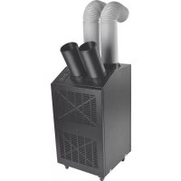
| Product Type | Self-contained air conditioning unit for 42U rack |
| Brand and Model | Tripp Lite SmartRack SRCOOL33K |
| Dimensions (H x W x D) | 199.3 x 60.3 x 122 cm (78.5 x 23.75 x 48 in) |
| Net Weight | 317.5 kg (700 lb) |
| Power Supply | 208-240 V~, 50/60 Hz, L6-30P plug or hardwired connection |
| Cooling Capacity | 33,000 BTU/h |
| Compressor | Inverter-driven variable speed DC |
| Refrigerant | R410a, 4 kg |
| Airflow (Evaporator) | 1000-1230 CFM |
| Airflow (Condenser) | 945-1012 CFM |
| Noise Level | <75 dBA |
| Control Panel | Multi-line LCD screen with interactive menu |
| Remote Monitoring | SNMP, Web, Telnet, Modbus (optional network card) |
| Main Functions | Precision cooling, dehumidification, condensate management by atomization |
| Air Filter | Removable, regular replacement with alarm |
| Warranty | 1 year limited (USA/Canada) |
| Materials | Steel and aluminum, black finish |
| Set Temperature | Default 25°C (77°F), adjustable |
| Humidification | Dehumidifier capacity: 0.85 gal/h |
| Preventive Maintenance | Cleaning filters and coils, checking condensate pump |
| Safety | Mandatory grounding, emergency stop, multiple alarms |
| Repairs | After-sales service via Tripp Lite, RMA authorization required |
Frequently Asked Questions - SmartRack SRCOOL33K Tripp Lite
User questions about SmartRack SRCOOL33K Tripp Lite
0 question about this device. Answer the ones you know or ask your own.
Ask a new question about this device
Download the instructions for your Air Conditioning in PDF format for free! Find your manual SmartRack SRCOOL33K - Tripp Lite and take your electronic device back in hand. On this page are published all the documents necessary for the use of your device. SmartRack SRCOOL33K by Tripp Lite.
USER MANUAL SmartRack SRCOOL33K Tripp Lite
Self-Contained Air Conditioning Unit
Models: SRCOOL33K, SRXCOOL33K
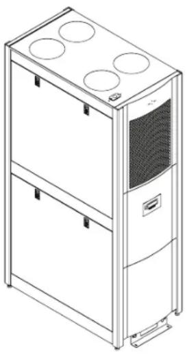
Table of Contents
- Introduction 2
- Important Safety Instructions 2
- Features 3
- Specifications 4
- Operation 5
-
Troubleshooting 11
-
Preventive Maintenance 12
- Storage and Service 14
- Warranty & Warranty Registration 15
Espanol 17
Francais 33
Pycckn 49


1111 W. 35th Street, Chicago, IL 60609 USA · www.triplite.com/support
Copyright © 2013 Tripp Lite. All trademarks are the sole property of their respective owners.
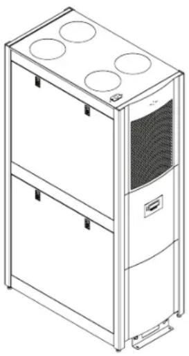
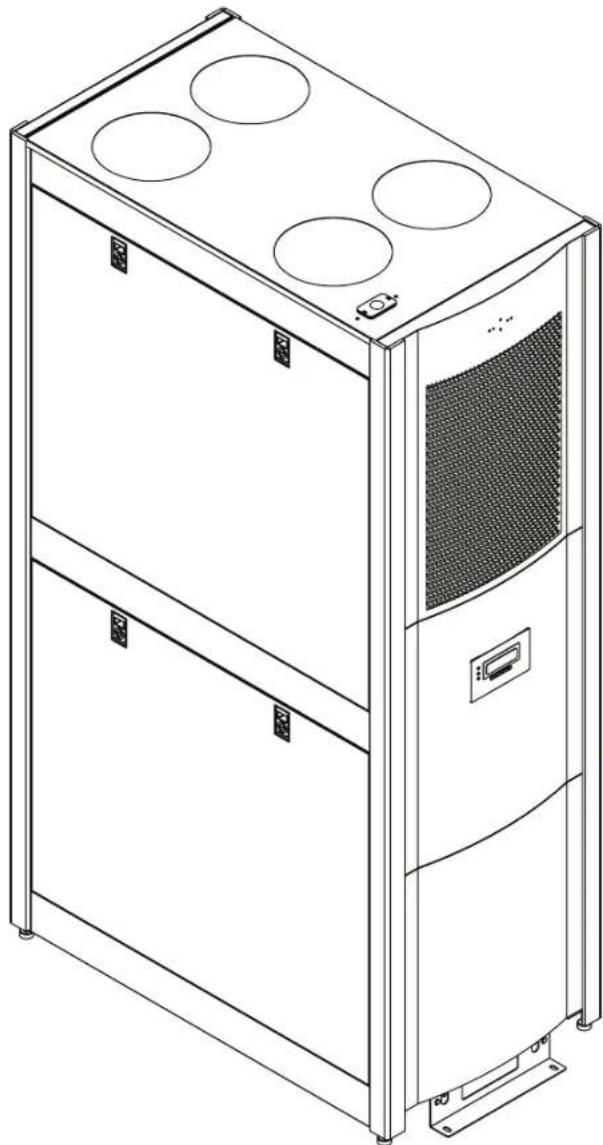
1. Introduction
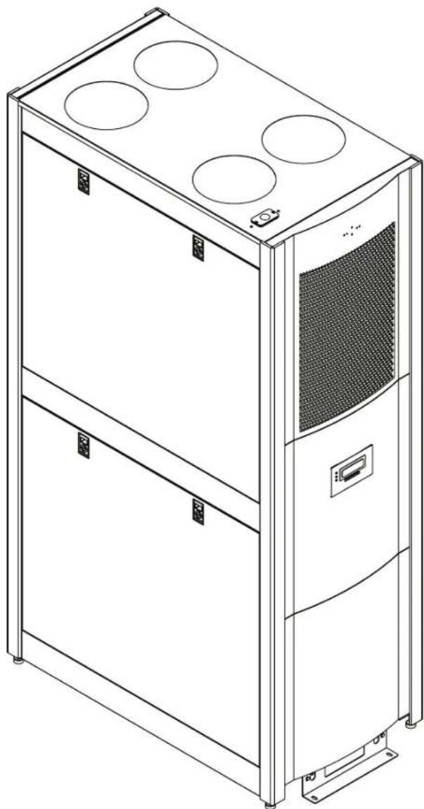
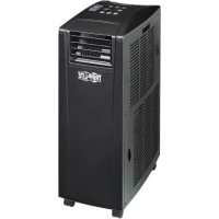
Tripp Lite's SRCOOL33K/SRXCOOL33K is a self-contained air conditioning unit housed in a standard 42U enclosure. The SRCOOL33K/ SRXCOOL33K is optimized for general computer room cooling or supplemental cooling in a large server room. It features an inverter-driven DC (direct current) variable-speed compressor that delivers high-efficiency precision cooling. This helps maintain set temperature without the traditional method of wasteful On/Off cycling.
A menu-driven, multi-line LCD screen provides on-site monitoring and control of various operating conditions. These operational conditions can also be monitored and controlled remotely via SNMP, Web, telnet or Modbus.
2. Important Safety Instructions

SAVE THESE INSTRUCTIONS
All sections of this owner's manual contain instructions and warnings that must be followed during the operation of the products described in this manual. Read ALL instructions before attempting to operate these products. Failure to comply may invalidate the warranty and cause serious property damage and/or personal injury.
- Prior to use, the individual user must determine whether this device is suitable, adequate or safe for the use intended. Since individual applications are subject to great variation, the manufacturer makes no representation or warranty as to the suitability or fitness of this device for any specific application.
- The cooling unit operates under pressure. Observe proper safety precautions when operating or servicing the unit.
- Do not operate the unit with any cover, guard, door, or panel removed unless the instructions indicate otherwise.
- Do not run cabling or service utilities in front of the fan outlets.
- Connect the unit directly to a grounded AC power outlet. Failure to do so may cause electric shock or fire. Note: If the unit is hardwired, the user should ground it according to local regulations.
The power supply for the unit must be rated as specified on the unit's nameplate. - Never modify the unit's plug or use an adapter if the unit is equipped with an input power cord.
Comply with all local and national wiring and safety regulations applicable where the unit will be installed, e.g. The National Electric Code (NEC) in the United States. - On models with an input cord, never use the cord as a means to turn the unit on or off. A serious electric shock may occur. Always use the control panel to power the unit on or off.
- Always turn the unit off and disconnect it from the mains input source by unplugging the unit or opening the mains circuit breaker before performing maintenance.
- Before connecting the unit to a dedicated drainage system, turn it off and unplug it.
- Maintenance should be performed by trained personnel only.
- Do not use thinners, alcohol, detergents or abrasive brushes to clean the unit's cabinet. These may damage the cabinet.
- Do not operate the unit without the air filter. This may cause dust accumulation that can damage the unit.
- Do not attempt to operate the unit in any room with inadequate air circulation. There must be adequate airflow to the condenser.
-
Do not place objects on top of the unit.
Prior to operation, ensure that: -
The unit has been properly installed in accordance with the procedures detailed in the Installation Manual
There is no evidence of damage to the unit
The unit is level and stabilized
The clearance around the cooling unit complies with local and national codes and regulations as well as the installation manual

- Warning! Do not use this equipment in the presence of a flammable anesthetic mixture with air, oxygen or nitrous oxide.
3. Features
33,000 BTU of cooling power
Variable-speed, DC-inverter-driven compressor and microprocessor-controlled electronic expansion valve (EEV) enable precision cooling adjustments
- Soft-start feature limits inrush current to prevent introduction of line noise, voltage disruptions and potential circuit overloads
- Self-contained, zero-maintenance unit atomizes condensate and expels it through the exhaust air stream—no floor drain, water collection tank, external condenser, refrigerant piping, ductwork or plumbing required when used in typical conditions
- Convenient LCD control panel and network interface enable local and remote monitoring and control of temperature, fan speed, alarms and logging via front-panel buttons, SNMP, Web, telnet or Modbus
- Row-based airflow path maximizes hot-aisle/cold-aisle efficiency and cooling predictability by supplying cold intake air high in the cold aisle and removing hot equipment exhaust air low from the hot aisle
Eco-friendly R410a refrigerant meets environmental standards worldwide
Nominal 208-240V AC Input, 50 / 60Hz frequency compatibility
4. Specifications
| Specification SRCOOL33K SRXCOOL33K | ||
| Input | ||
| Nominal input voltage 208-240V; 50/60Hz 208-240V; 50/60Hz | ||
| Input connection type L6-30P (Hardwire Optional) Hardwire (User supplied IEC 309 32 amp cord set, optional) | ||
| Input cord length (ft/m) 10 ft / 3.05 m 10 ft / 3.05 m | ||
| LEDs, Alarms and Switches | ||
| Controls Multi-line LCD control panel Multi-line LCD control panel | ||
| Physical | ||
| Unit weight (lb/kg) 700 / 317.5 700 / 317.5 | ||
| Unit dimensions (HWD/in) 78.5 x 23.75 x 48 | 78.5 x 23.75 x 48 | |
| Unit dimensions (HWD/cm) 199.3 x 60.3 x 122 | 199.3 x 60.3 x 122 | |
| Material of construction | Steel and aluminum | Steel and aluminum |
| Color | Black | Black |
| Form factor | Tower (42U equivalent) | Tower (42U equivalent) |
| Environmental | ||
| Cooling capacity (BTU) | 33,000 | 33,000 |
| Features | ||
| Dehumidifier capacity | 0.85 gal/hr | 0.85 gal/hr |
| Compressor type | DC, inverter-driven, variable speed | DC, inverter-driven, variable speed |
| Refrigerant (type/capacity) | R410a / 4kg (8.81 lbs.) | R410a / 4kg (8.81 lbs.) |
| Air flow | Evaporator: 1000-1230 CFM Condenser: 945-1012 CFM | Evaporator: 1000-1230 CFM Condenser: 945-1012 CFM |
| Amp draw | Variable (0-24 L6-30P; 0-30 Hardware) | Variable (0-24 L6-30P; 0-30 Hardware) |
| Sound level (noise) | <75dBA | <75dBA |
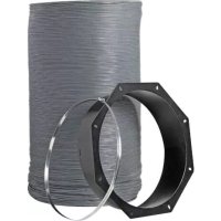
| Air tube length (in/cm) | 71/180 | 71/180 |
| Warranty | ||
| Standard limited warranty | 1 year (US/Canada only) | 1 year (Parts only) |
| Optional coverage (extensions of standard warranty period) | 2-year (WEXT3-SRCOOL33K); 4-year (WEXT5-SRCOOL33K) | Not available |
Regulatory Notice: This unit carries less than 22 lbs. of refrigerant and complies with all Department of Transportation shipping regulations. It is exempt from any additional requirements. The user does not have to make any extra accommodations to transport the unit.
5. Operation

Caution: Before attempting to operate the SRCOOL33K/SRXCOOL33K, ensure that it has been properly installed in accordance with the Installation Manual, including stabilization and sufficient clearance around the unit.
Tip Warning! If the unit has been tilted more than 15^ during shipping, unpacking or installation, allow unit to stand for 24 hours before turning on. Do not operate if there is visible internal or external damage.
5.1 Cooling Methods
The main function of the SRCOOL33K/SRXC0OL33K is to remove waste heat and return treated air to the room at the required temperature. The specific cooling method used is determined by the configuration of the rack enclosures in the room. The unit continuously varies the cooling output to maintain a set temperature at the return of the unit. The cooling output is varied by constantly adjusting the speed of the fans and the compressor. If desired, the fan speed may be set to a constant value by the user. Note: Setting a lower fan speed may limit the unit's capacity.
The unit uses the setpoint entered by the user to control the fan speed. This variable should be set based on the installation configuration.
Configurations
Room Cooling Mode: When the unit is installed stand-alone in a server room acting as a CRAC unit, the setpoint should be set to the desired room temperature.
In-Row/Hotspot Mode: When the unit is installed in a hot aisle/cold aisle configuration, the setpoint should be set to the desired cold aisle temperature plus the expected temperature rise across the problem rack ( 10^ ; 50^ ).
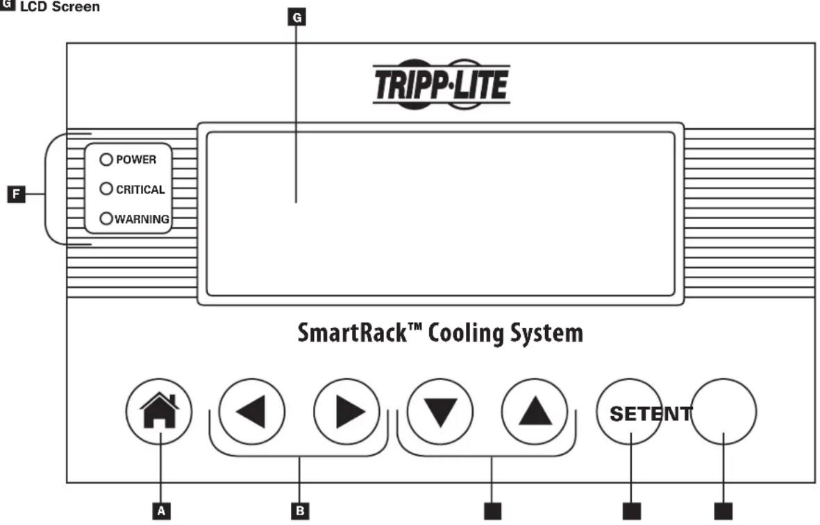
5.2 LCD Control Panel

Button leads directly to the HOME menu/Cancels input

Left/Right navigation arrows/Input adjustment buttons

Up/Down navigation arrows/ Input adjustment buttons

SET button scrolls through the input fields

ENT button confirms new value

Status LEDs

LCD Screen
5. Operation
5.3 Initial Operation
To Power the Unit On
1 Make sure that the SRC0OL33K/SRXCOOL33K is properly connected to the AC input source according to the Installation Manual.
To Change Initial Cooling Temperature
1 Scroll right to the SETUP Menu.
Press ENT to access the password screen.
3 Press SET to select Open Password option then press ENT to access the sub-menu.
4 The default password is 000000 and is already listed on the screen. Press SET to enter the password and press ENT to confirm.
5 The display will read SYSTEM UNLOCKED. The system will lock itself automatically after 3 minutes of inactivity.
6 Press the HOME button to return to the home screen.
7 Scroll right to the SETUP Menu.
8 Scroll down to the first sub-menu of the SETUP Menu.
9 Enter the desired Target Temperature using SET to select the temperature field and the up/down arrow keys to modify the numerical value. Press ENT to confirm new temperature.
10 Pressing the ENT key will now toggle the Cooling Mode ON and OFF.
Note: The unit has a factory default cooling temperature of 25^ C( 77^ F) .
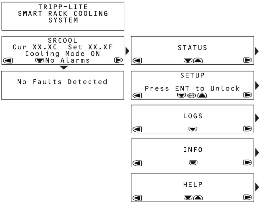
5.4 LCD Control Panel Menu Map
The SRCOOL33K/SRXCOOL33K is configured and controlled via an interactive, menu-based LCD Control Panel. Navigate from menu to menu by touching the left and right arrows. There are five menus: STATUS, SETUP, LOGS, INFO and HELP. When the SRCOOL33K/SRXCOOL33K is initialized, the HOME screen appears. The HOME and ALARMS screens are menus that alert you to the status of the unit. To navigate within a menu, use the up and down arrows.
5. Operation
5.5 HOME Menu and Alarms
The HOME menu indicates if the unit is operational, the current operating conditions and if there are any active alarms.
The HOME screen displays the current temperature and the set temperature the unit is trying to achieve.
If an alarm condition is indicated, details can be viewed by touching the down arrow. The SRCOOL33K/SRXCOOL33K can sense and display the following alarm conditions. (W) indicates a warning/advisory alarm; (!) indicates a fault that requires immediate attention.
Warnings
| Alarm Conditions Display User Action | ||
| Supply air sensor failure 1 (W)SUP AIR SEN FAIL Call Tripp Lite for service. | ||
| Condenser in sensor failure 3 (W)COND IN SEN FAIL Call Tripp Lite for service. | ||
| Condenser out sensor failure 4 (W)COND OUT SEN FAIL Call Tripp Lite for service. | ||
| Evaporator temperature probe fault 6 (W)EVAP TEMP FAIL Call Tripp Lite for service. | ||
| Air filter blockage/clog 9 (W)AIR FILTER CLOG Check the air filter for any blockage. Replace the air filter. Call Tripp Lite for service if error remains. | ||
| Air filter requires replacement | 10 (W)AF HOURS EXCEEDED | Check the air filter for any blockage. Replace the air filter. Reset the Air Filter Hours menu. Call Tripp Lite for service if error remains. |
| Excessive return temperature 20 (W)RETURN AIR HIGH The alarm set point is too low and the unit cannot keep up with the heat load. Reduce the heat load. If error remains, call Tripp Lite for service. | ||
| Excessive supply temperature | 21 (W)SUPPLY AIR HIGH | The alarm set point is too low and the unit cannot keep up with the heat load. Reduce the heat load. If error remains, call Tripp Lite for service. |
| Low suction pressure | 28 (W)LOW SUCT PRESS | Call Tripp Lite for service. |
| Water leak | 33 (W)WATER LEAK | Identify the water leak and correct it. |
Critical Faults
| Alarm Conditions Display User Action | ||
| Return air sensor failure 2 (!)RET AIR | SEN FAIL Call Tripp Lite for service. | |
| Suction temperature sensor fault 5 (!)SUCT TEMP SENSOR Call Tripp Lite for service. | ||
| High discharge pressure | 7 (!)HI DISCH PRESS | Check for any blockage of the condenser. Call Tripp Lite for service. |
| Suction pressure failure | 8 (!)SUCT PRESS FAIL | Call Tripp Lite for service. |
| Communications between controller and compressor have failed | 12 (!)INVERTER COM FAIL Call Tripp Lite for service. | |
| Remote shutdown has been closed | 13 (!)REMOTE SHUT DOWN | Reset the EPO or remote contact. If the error persists, call Tripp Lite for service. |
| Water pump failure | 14 (!)H2O PUMP FAIL | Check for any water in the upper tray. If the tray is full, pump the water out of the unit using the supplied hose and adjust any humidification systems in use. If the upper tray is dry, call Tripp Lite for service. |
| Condenser failure | 18 (!)COND FAILURE | Check for any blockage of the condenser. Call Tripp Lite for service. |
| Evaporator failure | 22 (!)EVAP FAILURE | Check the air filter and evaporator for any blockage. Call Tripp Lite for service. |
| Evaporator icing | 23 (!)EVAP ICE UP | Check the air filter and evaporator for any blockage. Call Tripp Lite for service. |
| Excessive discharge pressure | 24 (!)HIGH DISCH PRESS | Check for any blockage of the condenser. Call Tripp Lite for service. |
| Discharge switch failure | 25 (!)DISCH SWITCH FAIL | Call Tripp Lite for service. |
| Excessive system pressure | 26 (!)HIGH SYSTEM PRESS | Check for any blockage of the condenser. Call Tripp Lite for service. |
| System has run out of refrigerant | 27 (!)LOW CHARGE | Call Tripp Lite for service. |
| Persistent low suction pressure | 29 (!)LOW SUCT PRESS | Call Tripp Lite for service. |
| High and low pressures have not returned to nominal | 30 (!)LINE IMBALANCE | Call Tripp Lite for service. |
| Compressor failure | 31 (!)COMPRESSOR FAIL | Call Tripp Lite for service. |
| Fan failure | 34 (!)FAN FAIL | Call Tripp Lite for service. |
5. Operation
5.6 STATUS Menu
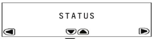
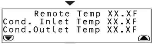
The STATUS menu provides information on current operating conditions. Touch the down arrow to access sub-menus.
The first sub-menu provides:
- Operating mode
Cooling output (estimated in kW)
Temperature of the air entering the SRCOOL33K/SRXCOOL33K
Temperature of the air leaving the SRCOOL33K/SRXC0OL33K
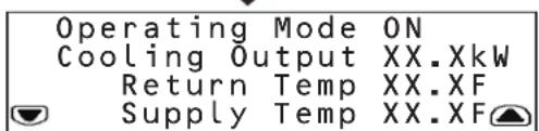
The second sub-menu provides:
- Temperature at the remote sensor
Temperature of the air entering the condenser
Temperature of the air leaving the condenser
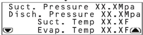
The third sub-menu provides:
- Refrigerant pressure at the compressor inlet
- Discharge pressure at the compressor outlet
Temperature of the refrigerant entering the compressor
Temperature at the evaporator
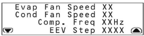
The fourth sub-menu provides:
- Speed of the fans that regulate evaporator air flow
- Speed of the fans that regulate condenser air flow
Frequency of compressor operation (in Hz)
Electronic expansion valve position
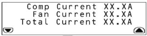
The fifth sub-menu provides:
Current the compressor is drawing
Current the fans are drawing
Total current for the unit
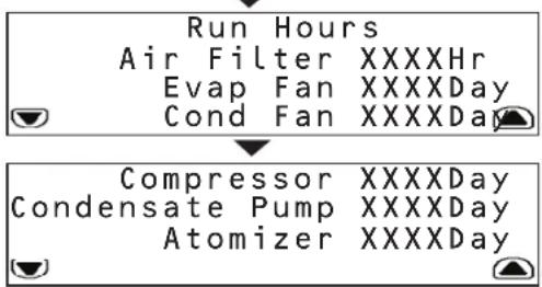
The sixth and seventh sub-menus provide the time the following components have been in use:
Air filter
Evaporator fan
Condenser fan
- Compressor
Condensate pump
Atomizer
5. Operation
5.7 SETUP Menu
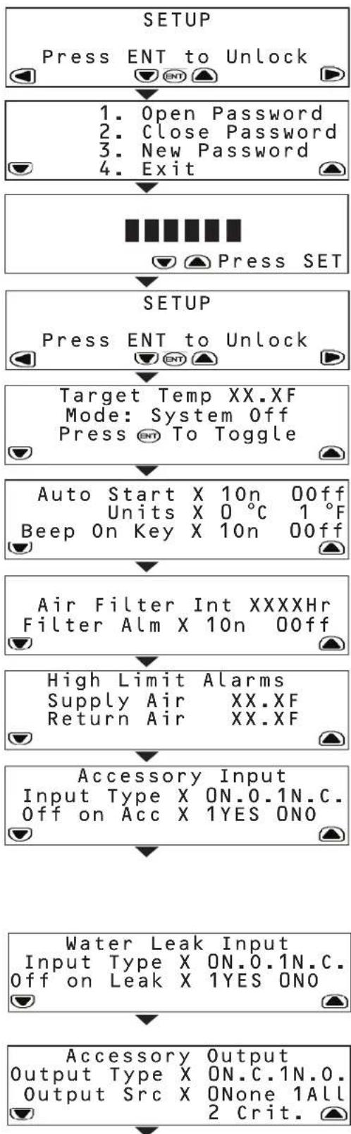
The SETUP menu enables you to set the operating parameters of the SRCOOL33K/ SRXCOOL33K. To access sub-menus, you must first unlock the menu by providing the assigned password. When at the initial SETUP menu, press ENT to bring up the password menu.
In the password menu, you have to option to:
- Enter the password to unlock the SETUP system
- Close the password and lock the system
Create a new password
To create a new password:
- Unlock the SETUP system with the current password. The default password is 000000.
- Scroll back to the password menu and use SET to scroll to 'New Password'.
- Press SET to access the numerical field and use the up/down arrows to enter the new password. Press ENT.
- At the confirmation menu, re-enter the new password and press ENT.
-
The unit will notify you if the password has been successfully changed.
-
Exit the SETUP menu
Note: Passwords can be up to six characters in length and must be made up of numeric values.
The first sub-menu allows you to input:
Target temperature of the room
System mode (On or Off)
The second sub-menu allows you to input:
- Whether the unit should start automatically when plugged in
Units of display (SI or English) - Beeping preference when keys are pressed
The third sub-menu allows you to input:
Hours until the air filter must be replaced
- Enable or disable air filter replacement alarm
The fourth sub-menu allows you to set high-limit alarms for:
Temperature leaving the SRCOOL33K/SRXCOOL33K
Temperature entering the SRCOOL33K/SRXCOOL33K
Note: The unit alerts you when either temperature exceeds your set value.
The fifth sub-menu allows you to input:
The normal state of the accessory input. (N.O. is defined as Normally Open while N.C. is defined as Normally Closed)
- Whether the unit shuts down if the input state changes
Note: The unit will always send a warning when the sensor changes.
The SRCOOL33K/SRXCOOL33K comes with an input contact that can be user
defined. The contact monitors a sensor and responds to any changes in the state of the sensor.
The sixth sub-menu allows you to toggle:
The normal state of the water leak sensor (Open or Closed)
- Whether the unit shuts down if a leak is detected
The SRCOOL33K/SRXCOOL33K comes with an output contact that can be user
defined. The contact monitors a sensor and responds to any changes in the state of the sensor.
The seventh sub-menu allows you to toggle:
The normal state of the accessory output (Open or Closed)
What type of alarm causes the output to change from normal
(None, All or Critical)
5. Operation
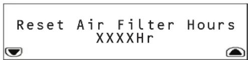
The eighth sub-menu allows you to reset the number of hours the current air filters has been in use.
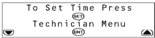
The ninth sub-menu allows you to set the time and access the Technician menu.

The Technician menu is used for changing the electrical current settings when using the unit in a hardwire configuration.
WARNING! Do not change this setting on the SRC0OL33K when using the supplied L6-30P input cord. Do not place setting at any other value other than 24.0 Amps (with Input Cord) or 30.0 Amps (Hardwire). Do not change this setting on the SRXCOOL33K.
Please consult the Installation Manual for further information.
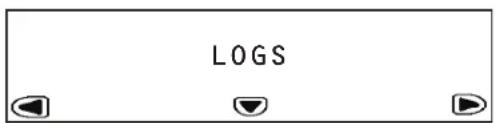
5.8 LOGS and INFO Menus
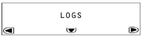
The LOGS menu provides access to the Event Log page. All alarms are entered into the Event log, tagged with a time/date stamp.
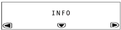
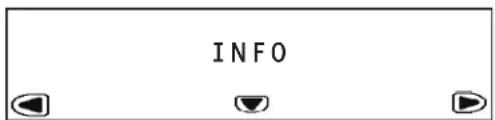
The INFO Menu provides access to the Information Page. This page displays the Model Name, Serial Number, Location, Unit Name and other information about the SRCOOL33K/SRXC0OL33K.
5.9 HELP Menu
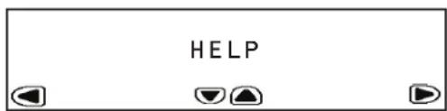
The HELP Menu provides an on-screen tutorial showing how to navigate through the menus and sub-menus.
5.10 Remote Monitoring and Control
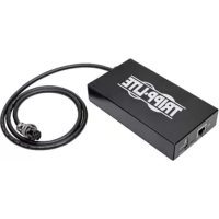
The SRCOOL33K/SRXC0OL33K can be remotely monitored and controlled via SNMP, Web, telnet or Modbus. Remote monitoring and control requires a network card such as Tripp Lite's SNMPWEBCARD (sold separately) in order to turn the SRCOOL33K/SRXC0OL33K into a network-managed device. Please consult the SRCOOL33K/SRXC0OL33K installation manual and web card documentation for further information on installing and configuring your network card. Update to the latest version of the SNMPWEBCARD firmware. It can be downloaded from triplite.com.
6. Troubleshooting
Locate the problem and review possible solutions in the following table. If the problem persists, visit www.triplite.com/support to obtain service.
| Problem Possible | Cause Possible Solution | |
| Fan fails to start. Cooling unit | shutdown due to an external command. | Disconnect communications cable and restart unit. |
| Faulty fan. Replace the fan. | ||
| Cooling unit cannot achieve setpoint. | Dirty filter. Clean filter. | |
| Dirty coil. Clean coil. | ||
| Heat load is too far away. Relocate | cooling unit. | |
| Improper fan speed. Fan speed set | to Low. Set fan speed to Auto or increase fan speed. | |
| Excess water in or around the unit. | Room humidity too high. Add drain | line. Adjust set point on humidifying equipment. Improve room sealing. |
| Dirty filter. Clean filter. | ||
| Dirty coil. Clean coil. | ||
| Cooling unit noise level is excessive. | Improper fan speed. Select lower fan speed. | |
| Water around cooling unit. Condensate drain hose not connected or not properly routed. | Verify proper connection of condensate drain hose, proper routing to pump and proper routing outside of cooling unit. | |
| Leak in drain system. Locate and repair leak. | ||
| Cooling unit not properly leveled. Adjust cooling unit's leveling feet. | ||
| Piping insulation damaged. Locate damage area and repair insulation. | ||
| Cooling unit operates but LCD panel does not function. | Local display not properly connected. | Verify proper connection of local display cable. |
| Unable to reset the switched circuit breaker. | Tripped high pressure switch. | Open unit's rear door and depress the high pressure cut off switch located above the compressor. Once reset, return the front panel circuit breaker to the ON position. |
7. Preventive Maintenance
Note: The following pages can be photocopied for use during scheduled maintenance. Tripp Lite recommends that completed maintenance forms be saved for future reference.
Self-Contained Air Conditioning Unit Preventive Maintenance
Tripp Lite SRCOOL33K/SRXCOOL33K MONTHLY MAINTENANCE CHECKLIST
Prepared By: Date:
Model Number Serial Number
General Inspection
Location of cooling unit
Temperature setpoint
Room temperature/humidity near the return of the cooling unit:
Temperature Humidity
Is the unit maintaining the temperature setpoint? Yes
Is there visible damage to the cooling unit, e.g. dents or scratches? Yes (Specify) No
Are there indications of environmental damage (dirt, dust, debris, liquid stains) around the unit installation area?
Yes (Specify) No
Previous month's alarm history:
Cleanliness Inspection
Check the condition of return air filters. Change if necessary.
Mechanical/Electrical Inspection

Caution!
Turn off the cooling unit and disconnect all power sources before performing mechanical and electrical checks.
Check the fan. All components should be moving freely, with no indication of binding or damage.
Verify that the condensate line is flowing freely.
Inspect the power cord and plug for damage.
7. Preventive Maintenance
Tripp Lite SRCOOL33K/SRXCOOL33K QUARTERLY MAINTENANCE CHECKLIST
Prepared By: Date:
Model Number Serial Number
Perform all Monthly Maintenance Checklist tasks PLUS the following tasks:
Mechanical/Electrical Inspection

Caution!
Turn off the cooling unit and disconnect all power sources before performing mechanical and electrical checks.
Inspect fan hardware and tighten if necessary.
Clean or replace filters.
Clean condensate pans.
Clean the condensate drain line.
Remove any debris from condensate floats.
Clean dust from door perforations.
Clean dust from fan bezels.
Verify proper functioning of the cooling operation mode.
Treat the drain pan with a plating product like Virginia Pan Tabs. Verify that the product you use is non-toxic, non-corrosive and will not leave deposits that could damage the unit and drain pan.
Note: Treating the drain pain helps eliminate problems such as odor, overflow and water damage by preventing plugged drain lines and openings.
Cleanliness Inspection
Check the condition of the drain pan and accumulation of debris in the pan. Clean as required.
Tripp Lite SRCOOL33K/SRXCOOL33K SEMIANNUAL MAINTENANCE CHECKLIST
Prepared By: Date:
Model Number Serial Number
Perform all Monthly Maintenance Checklist tasks PLUS the following task:
Inspect the evaporator and condenser coils and clean if required.
8. Storage and Service
Storage
Before storing the unit, confirm that all ducts and vents are secured or removed and properly stored. Also confirm that the unit is drained of condensation.
Service
Your Tripp Lite product is covered by the warranty described in this manual. A variety of Extended Warranty and On-Site Service Programs are also available from Tripp Lite. For more information on service, visit www.triplite.com/support. Before returning your product for service, follow these steps:
- Review the installation and operation procedures in this manual to insure that the service problem does not originate from a misreading of the instructions.
- If the problem continues, do not contact or return the product to the dealer. Instead, visit www.triplite.com/support.
- If the problem requires service, visit www.triplite.com/support and click the Product Returns link. From here you can request a Returned Material Authorization (RMA) number, which is required for service. This simple on-line form will ask for your unit's model and serial numbers, along with other general purchaser information. The RMA number, along with shipping instructions will be emailed to you. Any damages (direct, indirect, special or consequential) to the product incurred during shipment to Tripp Lite or an authorized Tripp Lite service center is not covered under warranty. Products shipped to Tripp Lite or an authorized Tripp Lite service center must have transportation charges prepaid. Mark the RMA number on the outside of the package. If the product is within its warranty period, enclose a copy of your sales receipt. Return the product for service using an insured carrier to the address given to you when you request the RMA.
9. Warranty and Warranty Registration
1-YEAR LIMITED WARRANTY
Sell w t i t t t t t t t t t t t t t t t t t t t t t t t t t t t t t t t t t t t t t t t t t t t t t t t t t t f
THIS WARRANTY DOES NOT APPLY TO NORMAL WEAR OR TO DAMAGE RESULTING FROM ACCIDENT, MISUSE, ABUSE OR NEGLECT. SELLER MAKES NO EXPRESS WARRANTY ISSUES. OTHER THAN THE WARRANTY EXPRESSLY SET FORTH HEREIN. EXCEPT TO THE EXTENT PROHIBITED BY APPLICABLE LAW, ALL IMPLIED WARRANTY ISSUES, INCLUDING ALL WARRANTY ISSUES OF MERCHANTABILITY OR FITNESS, ARE LIMITED IN DURATION TO THE WARRANTY PERIOD SET FORTH ABOVE; AND THIS WARRANTY EXPRESSLY EXCUSES ALL INCIDENTAL AND CONSEQUENTIAL DAMAGE. (Some states do not allow limitations on how long an implied warranty lasts, and some states do not allow the exclusion or limitation of incidental or consequential damages, so the above limitations or exclusions may not apply to you. This Warranty gives you specific legal rights, and you may have other rights which vary from jurisdiction to jurisdiction).
WARNING: The individual user should determine prior to use whether this device is suitable, adequate or safe for the use intended. Since individual applications are subject to great variation, the manufacturer makes no representation or warranty as to the suitability or fitness of this device for any specific application.
WARRANTY REGISTRATION
Visit www.triplite.com/warranty today to register the warranty for your new Tripp Lite product. You'll be automatically entered into a drawing for a chance to win a FREE Tripp Lite product!
* No purchase necessary. Void where prohibited. Some restrictions apply. Open to U.S. residents only. See www.triplite.com for details.
Regulatory Compliance Identification Numbers
For the purpose of regulatory compliance certifications and identification, your Tripp Lite product has been assigned a unique series number. The series number can be found on the product nameplate label, along with all required approval markings and information. When requesting compliance information for this product, always refer to the series number. The series number should not be confused with the marking name or model number of the product.
Tripp Lite follows a policy of continuous improvement. Specifications are subject to change without notice.


1111 W. 35th Street, Chicago, IL 60609 USA • www.triplite.com/support
1111 W. 35th Street, Chicago, IL 60609 EE UU • www.triplite.com/support
1111 W. 35th Street, Chicago, IL 60609 EE UU • www.triplite.com/support
Manufacturing Excellence
1111 W. 35th Street, Chicago, IL 60609 USA www.triplite.com/support
1111 W. 35th Street, Chicago, IL 60609 USA www.triplite.com/support
PykoB0dCTBO nOlb30BaTeIa
ABTOHOMHbI KOHdNcNoHep
Moden: SRC00L33K/ SRXC00L33K
CopepxaHne
-
BvBeHne 50
-
XpaHHe nTexHnueckoe 6cbnyKuBaHne 62
-
Baxhblye yka3aHnno TeXnKe 6e30nacchoctn 50
-
TapaHTnHbIe 06a3aTeJbCTBa n pernctpaunra paHTn 63
-
CboiCTba 51
English 1
- TexHuecknexapaKTepeNtKN 52
Espanol 17
- 3Knnnyataa 53
Francais 33
-
BbIaBHeHne uYcTaPaeHHe HncnPaBHoTei 59
-
PpoPnAaTneCckoe 6cnyKbAHne npemOH 60


Manufacturing Excellence.
1111 W. 35th Street, Chicago, IL 60609 USA · www.triplite.com/support
OxpaHcTc ABTOKIM npabOM 2013 Tripp lte. Bce TpobBme hAHH ABAHOTc MCKHOHTeBHO CObCTBEHOCTb CBMOX COOTBEETBAYUUX BnAaBmE
1. BvedeHne
Moenb SRCOOL33K/SRxCOOL33K npoH3BcDCTBa Tripp Lite npedctabniet cob0 ABTOHMh KOnHmHOp, BBynoHHehB CTaHdaptHom Kopnye BbCtO42U. Moenb SRCOOL33K/ SRxCOOL33K ONTMalbNo NOxOXHIT Dn8 o6uero OXNAJEDHMAaHHHO 3aA Hm DOABoOHrO OXAAJEDHBA CepBepHOM NOMEeHN M6bIeero OBeema. EOTNIHHTbeHOBIOOC6EHHO TBBOHETCAHmNE HHEBOPHRO KOMPeccoPAocNtOHHO TOKa CpeyunpyemO uactoT OBAuEHHo, OeCEeWBAIOe ToBcOKo3ΦeKTHBHO OXAAJEDHMe C B03MOJHOCTBO TOHOYCTAHOBKN Heo6xOIMM TeMnepaTyB. 3o NoMoraet NpOeepKaBaTB 3aADHHy ToMnepaTypeB 3cNIOb3OBAHn TpaDNIOHNO rCnO6ba, 3akIouAoJeERoCB KM6MHPOBAHHN 3Hepeo3TaPbTHb xIKNBo BKIIoueHH/NbIKNUoyHHa
Ynpabnemb C nmooubo MeHMOHOCTpOHyB KK-3KpaH o6eueMBAET BO3MOHcHOb TOKaHbHO KOHTpony H npabneHH pa3NHyBMpaOCHmpeKmAMn KoHTpoB m npabneHn 3TMM pa60mm peKHMAMM MOrTy TAKKe OcyuectBnAeBOA DctAHUHOH no npToKoAm SNMP, Web, telnet mnn Modbus.
2. BaxkhbIe yka3aHnNo texhNke 6e30naChoctn

COXPAHNTHE HACTOIIUE YKA3AHNIA
Bo Bcex pa3aIax hactoIero pykoBocTbA noIb3ObaTeIa coepkatay kka3AHn I npDynpkdeHn, KOTpIbe He6xOIMMo c6bnOaTbB npocece 3KcnpyaTuAMn OINCAHBix B HEM 3dEHN. Ipoc6Ba o3HaKOMtbc So BCEM YKa3AHmIM Do haayala EKcPiYATAuM DAHbX i3dEIn. HecobKeDeHne 3TxN yKa3AHn I npDynpkdeHn MOKeT pNBeCTN KaHHynPobAHIO rapaHTMN n npUHMtb cyueCTBeHNb MaTePnaIbHb yuepe Nnn Bpe 3IopOBbIIOeJ.
IpeHauanomHCNb30BAHn daHHOyCTPOCTBa NcBb3oAteBdoJHcB aTOM,TOO hABaTeCpNFOHbIM,COOTBCTBYUcMUN 6eONaCHbIM IINI pPeDnolaraEMOR npmHeHn. B CBA3u c6bHWM pa3HOoPbMaem KOHPeTHbIX npmHeHn PpO3BOUeB He DaET KAKNX-N60 3aBeEHn INI rapaHTM OTHOcHbHO pNPOHOCTN daHHOrO H3denia dKaKoro-Imo KOHPeTHorO npmHeHn IMI erO COOTBCTBn KaKM-N60 KOHPeTHbIM TpeOBAHnM.
Kohnmuhoep pa6oTaet noi daBneHem. Pn 3KcIpyataunnn TeXHmueckom 0cbnykBaHH nn DaHnHO yctpoCTBa cOblnoaTE Bc HndJeauae Mebp npedoctopoknoctn
He 3Kpnyatpyte daHnoe yctpoTcBO pnp CHaTOI KpbIwke, 3aunTHOM npncnoc6neHH, DBepue HIN naHEn 3a NCKNoueHem TEx CNYaeB, KOJa 3To npeDyCMtpHBaetcOoTBETCYIOUmm MHCTpykUmm.
He npoknaIbIaIe Ka6eINIIM KOMMYHkaIeN IpeE BeHTNIaIOHHbIM NTBePCTHMAI.
IopKJIIOUaIEyCTPOBHeOePcTeBENHO K3a3eMnHn0 p03eTKe cTeH npeMeHHOro TOKa. HecoBIOeHne 3TOr TpeBOAHN MoKET npHBecTH N opaJaeHN 3JIeKTPueckHM TKOM mN B03rOpaHNI. PpumueHue. B Cnyae Jecmko2o KaebbHOzo noeknoeHua daHNO zcmpcmba noIb3oBamel doJxH eobceHm b e20 3a3emne Hue coombemcbu C Mecmhmu HOpMaMbHbIM mpe6oBuHaMu.
HomHnHbHe npametpy 3neKtponntaHHa dHHORO yCTPOHCTBA DOJXHbCOOTBcTBOBaTb Yka3aHHbIM Ha e0 3aOBckoT a6nHke.
HnB KOem Cnyae H BHOCTe KaKHX-IM60 N3MeHeH N B KOHCTpyKcHIO pa3bema daHHoro yCTpoCTBa Hne NOJIb3yIITecb aadantpeom B TOM Cnyae, eCIN yCTPOICTBO OCHaUeHO BXOHNbIM
Cobnndte Bce MeTbIe H ouhauHohalbIe HOpMbI npBnHa 3eKpOMHTaHa I TexHNI 6eOaHcOHT, DeCTByIOue Ha Toi TeppuTopm, Tne npednonaraetca yctahOBKa daHHoro yctpoCTBa, HapnPmep, HauHouHbHm CBOd 3aKoHO B n CTanaptro No 3eKpToexHKe (NEC) BC llaA.
B Moedjx, OchaeHHbIX BxDhbl mHpyom, H N Koem Cnyae He nCnOJb3yIte eR O KaueCTBe cpeCTBa BkIOUeHn IIN BbIKIOUeHn YcTPOIHCTBa. 3To Moket npHBecTu KOnaChomy nopaxEHNO 3NekTPnueckm TokOM. IIN BkIOUeHn IIN BbIKIOUeHn yctpoCTBa nCnOJb3yIte TOnBko COOTBeCTByIOUne 3NeEMHTb NaHEn ynpabNEHn.
- IpeH naIom pa60T no texnueckomy o6cnykBaHHuO yctpoCTBa 6b3aTeBbHO BbIKIOaHTe ero N OTOeHNHaTE OT NTOCHNKA CETEBORO 3NEKPTPOHTHNA IyTeM BbHIMAHIN BUNKN H3 po3ETKn cTeHnn p3MbKaHnA CETEBORO aBtOMaTHueCKrO BbIKIOHATEII.
- Ipeepnoknouehm yctpoTBA K CneuaHnBnPOBaHHoJ DpehaxHoCtemeeroEeYet BbIKNoHTb NOTcOeHNHTb OTcETN 3JeKTPoNTaHnA.
TexHHueckoe 6cbnyKbAHHe OJINKHO OCUyEeTBaTbCra TOLbKO CNEuaHCTAMC CCOOTBeCTBHyOe NOIROTOBko.
-ДяочNTКИКорпуca Данногу оустретва He noIb3yIteb pa36baIITeIaMIM, cIINPTaMIM MOIOUIMM CpeDCTBaMIM IIN A6pa3NIBbIMM UTeKAM. 3To MoXET pInBBeTn K nobpeJckDeHIO KORpYca.
HeeknnyatnpyTe daHnoe yctpoCTBO 63 Bo3dyuHoro fNtpoT. To MoKet npHBcTm K cONPHeHIO nbIIM C nocJeDuM mOBpeJdHEm yctpoCTBA.
HeeknnyatpyntaDnHoe yctpoiCtBO B kAkmN-nmOneuHnx C HeoocTaTOOH uKpkyuaeB03dyxa. Heo6xoDMo o6ceueHne doCTaTOHO npriTOKa BO3dyxa K KOHeHcTOpTy.
He nomeaaiTe KaKne-Im6o npEmeTbI noBepx yctpoiCTBa.
- Neped hauanom pa60tbl cneyeT o6ecneHtB:
- npaBnIbHyO yCTaHOBky DaHHO rYCTPOcTBa corIacHo nopAky, n3IOKeHHoMy B PyKoBOcTBe no MoHTaKy;
OTCYTCBME BUNIMbIX NOBpeKdEHN yCTpOCTBA;
POBHOeIyToHmBOe paCNOJXeHHe yCTpoCTBa; - HAIYIe CBO6oHOrO IPOcTpaHCTBa BOKpyr KOHNIOHOHePc cOITaCHO MeCTbIM IOUeEOCyapCTBeHHbIM HopMaM IN paBILAM, a TAKKe pyKOBOCTBy IO MOHTaKy.

BHHMaHHe I He nCnObn3yIte daHnoe oobOpDyBaHMe B npNcyTCTBm BOCpNaMeHHOeCi aHEcTeTMECKo CMEc C Bo3DyOM, KINcNoPdOM mnn 3aKnbcIa 30TA.
3.CboyCTBa
0xnaKaDaua cnoc6HocTb 33000BTU (6pHTaHcKHX TeNIOBbIX eHNHI)
- INBepTOpHbKOMnpeccop NoCToAHHOrTo TOKa c perynpyeMoH qACToToB BpaueHn HneKTpoHHb paunPtehBb BEHTNb CMHKpOPOeCCOPbM ynpAbeHem oecneuBaHT Bo3MOXHOCTb TOHcH perynpoBKN npametPoB OxJaakDeHn
- OyHKUaIJIABHOIpyCKaOrpaHmVbAeB6pOcK npEoTbPaauaB O3HKnHOBeHMe UyMoB BInHn, npoOeB HapJxKeHN I Bo3MOXhIx nepperpy30k cien
A ToHOMHm, Heo6cnyKnaeMbmy arperat oobceuWbaet pactbIineHe KOHNHeCATA Hero BbIOd C nTOKOM BblnckaemrO Bo3dyxa, 10To MCKNHOaET Heo6xoIMocTB HAnHUMCNIIBHO OTBepTBA NONY, pe3epByapa dnc6opa BDOby, BHeuHrero KOHNecHcatopA, TpyoOpnoBoDn IINpKyIaun XnadaReHa, CNTEmbBo3dyuHbIX KaHANOB INN NOkKnueHn K KaHAN3auH, Tpe6yeMbix npn HCNOIb3OBAHm B TNIOBx ycIOBHX
- yD6HnKoKpCTaJIHueckra NaHbIy npabHe HcTeB0 INHTepEeO bcceuHbAOT Bo3MOHOrIO NDCtAHUHOHor KOHTPONHy npabHe TEmpeatpyo, CkopoctbBOpaHnBEHTnATopAp, CnHnHa3aueH n pRnCTpaueH npametPoB c nomoub kHONKepeJeHn aeHn IpToKOB SNMP, Web, telnet nn Modbus
PaeHoe paonnoJeHne BO3dyXOBIOB o6eNeuBaET MaKcMaIbHyO 0eFKeTMBHOCT npoxKeHnnoTOKOB rpoAero/XoNOHOBO3DyxA npeKa3yeMOCT npaMeTPOB OxNAJDeHHaCCHOT NOAHNoCTNpOHTNOUeEO XoNOHOBO3DyxA B BepxHOOqCTb "xoNOHO" npoTe a ydaNEHnO tOBMOrO t OBPOYOBANHn rpoAero BO3DyxA HKKHeH cHtIN "rpoAero" npoTeA
3KoONrWccknYCTbXyIaIaReHRT410a yIOBJeTBoPaeTpe6oBaHmM MeKdyHapOaNbIX npRpoOooXpaHHbx CTaHApTOB
HITAHHEOTcEHNEPEMeHHOrTOKa208-240B,COBMEChMocTbCCETAMNAACTToT50/60T
4. Texnueckne xapaKTepeNtIKN
Hakmte SET nBb6opa Open Password (otKpbItb napoi), a 3aTe m HAKMTE ENT nBxOa B noMeHO.
HaKpaHbBOIDTc npHcBoEHnI no yMOnHnIO npoB 000000.HaxMMTE SET IIN BBOda npoia, nOce Yero HaxMMTE ENT IIN erO noITBePExeHHa.
Ha dncnne noaBntca coo6eHne SYTEM UNLOCKED (CNCTEMA PA3bIOKPOBAHA).PnO tcyTbHn AKTHBNOCTM NOIb3OBaTeRn B TeueHne 3 MHyT CnCTema ABTOMATUcckn 6IOKpyetca.
Hakmnte KhoNkYo HMOIa Bo3bPaTa Ha ochOBHO kpaH.
Ppokpytnte Bnpabo Do MeHIO SETUP (HaahJIbHbIy yCTAHOBKn).
Ipokpytme BnH3do npebBorpo nOMeHo B MeHo SETUP.
BBeIe Jeaemoe 3aueHme uebeo TemepatpybI, Hcnobn3y SET dna Bb6pa Tmepatpyhoro nla KnaBn CtpenBvBepx/Bn3 dnM3MeHnHnMnHnHO 3aueHn.
HaxMMTEENTIINIOBTepeKHeHNOBO3HaueHHTeMnepaTypb.
Tenepb KnaBnA ENT byet cnJyKntb dN BKNIOUeHm N BbIKIOUeHm pexkMa oxnaJeHHa.
IpmeuHue,Ja daHnzo ycmpoUmba 3abodckaa hcmpoia kmemnpampyb oxxadhen noymouanuo coomraern 25℃(77℃)
5.4 Ctpyktypa MeHIO KK-naHEn ynpabHeHH
yctpoiCTBO SRCOOL33K/SRXCOOL33K KOHfhypnyeTcN yynpaBnAe TceE hntepaKmbHyoo KX-naneIb ynpabneHa o cHOBe MeHIO. IpexoDITE uO dHOrO MeHIO Bdyroe HaxaTMem CTpeoK "BnEo" N "Bnpabo." Bcer Bo CmTeMe IMeeTc PAIb MeHO: STATUS (CTATYC), SETUP (HAJALbHAR YCTAHOBKA), LOGS (JKPHAlbl), INFO (MHFO) HELP (CIPABKA). PpHIMUmaHuaMn yctpoCTBA SRCOOL33K/SRXCOOL33K NOBnAeTcR kpaHnoe MeHo HOME. 3kpaHbIe MeHO H ALRMS npedctabnHOT co60m MeHIO, coo6uauuue BAM O CTatye yctpoCTBa. DnpepeMeueHna BByTPn TORI MIN MHO IO MeHO Nolb3yTeB CTpeKaAMN "BBePx" "BHN3".
TRIPP-LITE SMART RACK COOLING SYSTEM
SRCOOL Cur XX.XC Set XX.XF Cooling Mode ON No Alarms
No Faults Detected
STATUS
SETUP
Press ENT to Unlock
LOGS
INFO
HELP
5.3Kcnnyataua
5.5 MeHIO HOME (HA4AIO) n npdeynpeDntBhbie CnHaIb
MeHO HO MOKa3bIAeT, HAKOHTCAI YCtpoBTO B paoueM cOCTaHNN, efo TeKuyiIM peKIM paobToH hAIHNIcpeDyIpneITbeHbIX CNHAnOB B KOHNpTeBHm MoMeHn.
Ha 3kpaeHOMe OTo6paXaetra TeKUeEe 3aueHHe TemnepaTpybI yCTaHOBNEHoe 3aueHHe TemnepaTpybI, KOtopoRo DAHHoe YcTpoCTBO nbTaTeC TdoCTM.
Bcnyae otobpaexhena kaoi-n6o onachoH cmtyaunipocmOp ee noopbohoro ooncaHnO cyuntctra nyem hakta TcpeKN "BHN". YcptcoTb0 SRCOO133K/SRXCOOL33K MOkET bblnTb 0toobpaaatcbnekyuune onaChbe cmtyaun.(W) 03haaet haHnme npdynpdtntbHor/ho/HnOpmauHOHOR cHtHa; (I) 03haaet haHnme HnCnPabHcHt, Tpe6yooie HeMeDnenHOr BHMAMHA.
PpeDynpexkdenia
IpeBoeNoDMHeHIOaETB03MOXHOCTbBBOJNTb:
- TceneByo TemnepaTyP noMeueHn
CnCTeMHbI pexMM (Bkn nn BbKn)
Btopoe noMeHO daet BO3MOxHocTB BBOIDHT:
3aHaHe Ha aBtOMaTnueckn 3aNyck npBkNIOeHm B cTeb
EHHHbIOTOBpaKaemOHΦOpMaunn(CHNHeMeTpueckne)
PepnoHTeBbH3BkyOBoCMHaI npHaXaTMKnAaB
TpeBte NOIMEHIO Daet BO3MOXHOCTb BBOJNTb:
KolmucCTBOaC0Bdo Heo6xOIMMo3AmeHb BO3DyHOrO foNlbTa
3aDHaHe HaakTbuaHIO HIN DeaKTbuaHIO INpeDynpedHTenbHoro CMTHana O Heo6xoHMOCTN 3aMeHbB03dyHoro fHnTpTa
YeTBePToe NoDMHeIO DaET BO3MOXHOCTb 3aDaBaTb npeDyInpeDHTenbHbIe CMHaBbO DOCTMKeHN BepxHIX npdeEhBbix 3NaHeHn DIA:
TemnepaTpybHaBbXoJe SRCOOL33K/SRXCOOL33K
TemnepatypbHa BxOe SRCOOL33K/SRXCOOL33K
Ppumeyaue. Ycmpoem80 coo6aem o npebwneu HIO620 u3 aadnHbix nonb30aemeim 3auehu.
Praoe NoDMeHIO DaET B03MOXHOCTB BBOIDtB:
- Hopmaibhoe coctoHnne ha BXOe yCTpOcTBA. (N.O. 03Haayet HopmaibHo pa30MKHyToe, a N.C. - HopmaibHO 3aMKHyToe)
3aHaHe OTKIOHcHHeYCTPOIcTBa PnN 3MeHHeM COCTOHHa HxOe Ipumeyue. YcmpoICMbHO HanpaBnaem npdeynpeXdHe npu KaKdoM U3MeHHeu ccoMoHHa damuKa.
UcTPOCTBO SRCOOL33K/SRXC0OL33K NOCTynae C BXOHDHM KOHTAKTOM, COCTOHHE KOtOPORo MOKeT ONpeDJIbTaONb3OBATEmE. 3OT KOtAKT OTCENEXMBAET COCTOHHE DaTUnKa HpeaHpyet Ha NIObIe I3MeHeHr erO coCTOHnI. WeCtoe noIDMeHO daTe BO3MOxHocTB NepeKNIQaTb:
HopmaHoe coctOHHe DaTHKa yTeKu BObI (pa3OMKHyTOe Hn 3AMKHYToe)
3aHaHe Ha OTKIOUeHHe yCTPOIcTBa npn 06hApHyKeHHyTeKu
UyctnoCTBO SRCOOIL33K/SRXCOOIL33K noCTynaet C bIXbOHNbIM KOHTAKTOM, COCTOHNHE KOtOporo MOKeT ONpeJeIbTaCBnIb3oBaTeMe. 3ToT KOHTAKT OTCNEKINBAeT COCTOHNHe DaTuKHa IpeaHpye Ha NIOBble H3MeHeHRA erO COCTOHNHA.
CeIbMoE IOIMeHIO Daet BO3MOXHOCTb NepeKIOHcAaTb:
HopmaBhoe coctoHHe Ha BbXOJe yCtpOnCTBa (pa30MKHyToe nn 3AMKHyToe)
TIN npDynpdntBnHO rCnHa, Bb3bBAIOeRr N3MeHeHMe COCTOHN Ha BbIXOe H3 HopMaIbHO (OTCYTCTByET, BCE INN KpUInueckn)
5.3Kcnnnyatauia
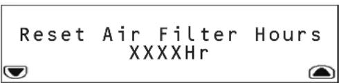
BocbMoI NOmEHIOEcneHnBaET Bo3MOxKHOCTb C6pOCA KOINHECTBa YacOB INONb30BAHNy yCTaHOBNEHHbIX B0DyUHbIX fHbTPOB.
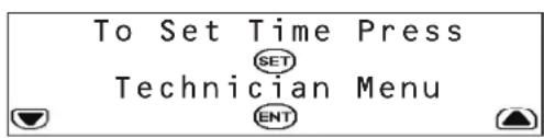
DeBraeNoDMHeHO 06ecneHbAeB 03MOxHObCTyTahOBKn BpeMeHN HxOJa B MeHIO Technician (HaJauNK).

MeHIO Technician IcnoNb3yETcIgI NImMeHnna napaMetpo 3JIeKTPueCKoTo TOKa npH cNoIb3OBAHm yCTpOCTBa CKeCTKIM KaBbHbIM NOkIKNuEHnEM.

BHMMAHIE! He MeHnIte DaHHyO NaCTPOky B MoDen SRCOOL33K npn MCNoIb3OBaHmB XbOHDoro Ka6eLa L6-30P, noCTabNlAemOro B KOMPiNeKe. Te. HnpNCBaHbIaTe DaHHomy npaMaTepy 3NaHeHme, OTMNHOe O24,O A (pyn MCNoIb3OBaHmB XbOHDoro Ka6eLa) mnn 30,O A (pyn JeckTcOM Ka6eNbHm ONDKNUChHm) He MeHnIte DaHHyO NaCTPOky B MoDen SRXCOOL33K.
Bone noDpo6hyo HhphiOpmauHcM. B PykoBOCTbe NO MoHTaKy.
5.8 MeHIO LOGS (XyPHAJIbl) u INFO (MHOO)
MeHIO LOGS oecneuBaet doctyn K ctpaHnue Event Log (Xyphan co6bTm).Bce npedynpeDntenbHbe crHnbl BHOATCR BxypHAN co6bTm C metKoBpEMHe/daTb.
MeHIO INFO o6ecneuBaet doctyn K cTpaHnue Inforamation (HfOpmaa). Ha 30i TcpaHnue OTo6paKaetca HauMeHoBaNHe MoJeIe, cepHbHbHOMep, MeTo yCTaHOBKn, HauMeHoBaNHe yCTpOCTBa I IpOue CBeDeHNr O6 yCTpoiCTBe SRCOOIL33K/SRXCOOIL33K.
5.9 MeHIO HELP (CTIPABKA)
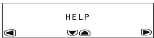
MeHIO HEPIpeTcbTaeT cobOeKpaHnoe nocbOeNo nepeMeueHnBHytn MeHO nnoMeHo.
5.10ДиctaHOnHHb KOHTpOJIb uynpaBneHne
Kohtpnb uynpablenhe yctpoiTbOM SRCOOL33K/SRXC0OL33K MOyT TAKKE OuyueCTBnTbCA mntaHIOHO no npoToKoanSMNP, Web, telnet nIe Modbus. IIN dmtauHHOHO KOthponnyu npablenh Tpe6yETc ceteBa Kapta, Hanpimep SMPWBCARD npo3BOcTBa Tripp Lite (npoaeTc oTdeNbno), npebpaauoana SRCOOL33K/SRXC0OL33K B yctpoiCTBO C cetEBIM npapablenhem. Bonne npoDp6Hy nHooPmaunho 06 ytaHOBKe n Hacptoe K eotbeo Kahtb moHNO pOnyUHTb n pykoBDCTBA no MoHTaKy ycTpoiCTBA SRCOOL33K/SRxC0OL33K u dokymehaum K Be6-kapte. 06HOBNTe npoWbky yctpoiCTBa SMPWBCARD do noocneHn BepCN. Ee moHNo 3aRpy3ntb caai triplite.com.
6. BbIaBHeHne uYcTpaHHe HEnCnPaBHOCTe
HaHnIte np6bemy nO3aKoMbtec b O3MoXbHbIM cno6abm ee peuehen B cnekyoue Ta6nue. B cnuyae coxpaHennBa3HKwe np6bembl nocetnte ctpnHy www.triplite.com/support dnnolnyehn Texhueckoi noepdkn.
Manufacturing Excellence
1111 W. 35th Street, Chicago, IL 60609 USA · www.triplite.com/support
14-11-20 9:30 PM

- Self-Contained Air Conditioning Unit
- Table of Contents
- Introduction
- Important Safety Instructions
- SAVE THESE INSTRUCTIONS
- Features
- Specifications
- Operation
- Cooling Methods
- Configurations
- LCD Control Panel
- Initial Operation
- To Power the Unit On
- To Change Initial Cooling Temperature
- LCD Control Panel Menu Map
- HOME Menu and Alarms
- Warnings
- Critical Faults
- STATUS Menu
- The first sub-menu provides:
- The second sub-menu provides:
- The third sub-menu provides:
- The fourth sub-menu provides:
- The fifth sub-menu provides:
- The sixth and seventh sub-menus provide the time the following components have been in use:
- SETUP Menu
- In the password menu, you have to option to:
- The first sub-menu allows you to input:
- The second sub-menu allows you to input:
- The third sub-menu allows you to input:
- The fourth sub-menu allows you to set high-limit alarms for:
- The fifth sub-menu allows you to input:
- The sixth sub-menu allows you to toggle:
- The seventh sub-menu allows you to toggle:
- LOGS and INFO Menus
- HELP Menu
- Remote Monitoring and Control
- Troubleshooting
- Preventive Maintenance
- Self-Contained Air Conditioning Unit Preventive Maintenance
- Tripp Lite SRCOOL33K/SRXCOOL33K MONTHLY MAINTENANCE CHECKLIST
- General Inspection
- Cleanliness Inspection
- Mechanical/Electrical Inspection
- Caution!
- Tripp Lite SRCOOL33K/SRXCOOL33K QUARTERLY MAINTENANCE CHECKLIST
- Tripp Lite SRCOOL33K/SRXCOOL33K SEMIANNUAL MAINTENANCE CHECKLIST
- Storage and Service
- Storage
- Service
- Warranty and Warranty Registration
- 1-YEAR LIMITED WARRANTY
- WARRANTY REGISTRATION
- Regulatory Compliance Identification Numbers
- PykoB0dCTBO nOlb30BaTeIa
- ABTOHOMHbI KOHdNcNoHep
- CopepxaHne
- BvedeHne
- BaxkhbIe yka3aHnNo texhNke 6e30naChoctn
- COXPAHNTHE HACTOIIUE YKA3AHNIA
- 3.CboyCTBa
- Texnueckne xapaKTepeNtIKN
- Ctpyktypa MeHIO KK-naHEn ynpabHeHH
- 5.3Kcnnyataua
- MeHIO HOME (HA4AIO) n npdeynpeDntBhbie CnHaIb
- PpeDynpexkdenia
- 5.3Kcnnnyatauia
- MeHIO LOGS (XyPHAJIbl) u INFO (MHOO)
- MeHIO HELP (CTIPABKA)
- 5.10ДиctaHOnHHb KOHTpOJIb uynpaBneHne
- BbIaBHeHne uYcTpaHHe HEnCnPaBHOCTe
Brand : Tripp Lite
Model : SmartRack SRCOOL33K
Category : Air Conditioning