
LUKE 700 RGB - Laser pointer Cameo - Free user manual and instructions
Find the device manual for free LUKE 700 RGB Cameo in PDF.
| Product type | Professional laser projector for shows |
| Brand | Cameo |
| Model | LUKE 700 RGB |
| Colors | Red (650 nm), Green (532 nm), Blue (447 nm) |
| Total power | 700 mW |
| Beam diameter | 3 mm |
| Divergence | 2 mrad |
| Laser class | 4 |
| Scan angle | 60° |
| Galvanometers | 30 kpps at 8° ILDA |
| Built-in presets | 128 |
| Control modes | DMX (4/11 channels), ILDA, automatic, sound, Master/Slave, standalone |
| DMX connectors | XLR 3-pin male (input) and female (output) |
| ILDA connectors | Sub-D 25-pin male (input) and female (output) |
| Mains power | 110-240 V, 50/60 Hz via Neutrik PowerCON |
| Power consumption | 75 W |
| Fuse | F2AL / 250 V |
| Dimensions (W x H x D) | 215 x 157 x 225 mm |
| Weight | 4.5 kg |
| Housing material | Metal (aluminum) |
| Cooling | Silent fan |
| Safety | Key lock, emergency stop connector (Interlock), Scan Fail Safety system |
| Operating temperature | 10°C to 40°C |
| Relative humidity | 10 to 70%, non-condensing |
Frequently Asked Questions - LUKE 700 RGB Cameo
User questions about LUKE 700 RGB Cameo
0 question about this device. Answer the ones you know or ask your own.
Ask a new question about this device
Download the instructions for your Laser pointer in PDF format for free! Find your manual LUKE 700 RGB - Cameo and take your electronic device back in hand. On this page are published all the documents necessary for the use of your device. LUKE 700 RGB by Cameo.
USER MANUAL LUKE 700 RGB Cameo
natural_image
Exterior view of a black Luke 1000R68 laser unit with camera and warning label (no readable text beyond branding)LUKE SERIES
ANIMATION LASER
CLLLUKE400RGY / CLLUKE700RGB /CLLLUKE1000RGB
EN You've made the right choice!
We have designed this product to operate reliably over many years. Please read this User's Manual carefully, so that you can begin making optimum use of your Cameo Light product quickly. Learn more about Cameo Light on our website WWW.CAMEOLIGHT.COM.
- Please read these instructions carefully.
- Keep all information and instructions in a safe place.
- Follow the instructions.
- Observe all safety warnings. Never remove safety warnings or other information from the equipment.
- Use the equipment only in the intended manner and for the intended purpose.
- Use only sufficiently stable and compatible stands and/or mounts (for fixed installations). Make certain that wall mounts are properly installed and secured. Make certain that the equipment is installed securely and cannot fall down.
- During installation, observ e the applicable safety regulations for your country.
- Never install and operate the equipment near radiators, heat registers, ovens or other sources of heat. Make certain that the equipment is always installed so that is cooled sufficiently and cannot overheat.
- Never place sources of ignition, e.g., burning candles, on the equipment.
- Ventilation slits must not be blocked.
- This appliance is designed exclusively for indoor use, do not use this equipment in the immediate vicinity of water (does not apply to special outdoor equipment - in this case, observe the special instructions noted below). Do not expose this equipment to flammable materials, fluids or gases.
- Make certain that dripping or splashed water cannot enter the equipment. Do not place containers filled with liquids, such as vases or drinking vessels, on the equipment.
- Make certain that objects cannot fall into the device.
- Use this equipment only with the accessories recommended and intended by the manufacturer.
- Do not open or modify this equipment.
- After connecting the equipment, check all cables in order to prevent damage or accidents, e.g., due to tripping hazards.
- During transport, make certain that the equipment cannot fall down and possibly cause property damage and personal injuries.
- If your equipment is no longer functioning properly, if fluids or objects have gotten inside the equipment or if it has been damaged in anot her way, switch it off immediately and unplug it from the mains outlet (if it is a powered device). This equipment may only be repaired by authorized, qualified personnel.
- Clean the equipment using a dry cloth.
- Comply with all applicable disposal laws in your country. During disposal of packaging, please separate plastic and paper/cardboard.
- Plastic bags must be kept out of reach of children.
FOR EQUIPMENT THAT CONNECTS TO THE POWER MAINS:
- CAUTION: If the power cord of the device is equipped with an earthing contact, then it must be connected to an outlet with a protective ground. Never deactivate the protective ground of a power cord.
- If the equipment has been exposed to strong fluctuations in temperature (for example, after transport), do not switch it on immediately. Moisture and condensation could damage the equipment. Do not switch on the equipment until it has reached room temperature.
-
Before connecting the equipment to the power outlet, first verify that the mains voltage and frequency match the values specified on the equipment. If the equipment has a voltage selection switch, connect the equipment to the power outlet only if the equipment values and the mains power values match. If the included power cord or power adapter does not fit in your wall outlet, contact your electrician.
-
Do not step on the power cord. Make certain that the power cable does not become kinked, especially at the mains outlet and/or power adapter and the equipment connector.
- When connecting the equipment, make certain that the power cord or power adapter is always freely accessible. Always disconnect the equipment from the power supply if the equipment is not in use or if you want to clean the equipment. Always unplug the power cord and power adapter from the power outlet at the plug or adapter and not by pulling on the cord. Never touch the power cord and power adapter with wet hands.
- Whenever possible, avoid switching the equipment on and off in quick succession because otherwise this can shorten the useful life of the equipment.
- IMPORTANT INFORMATION: Replace fuses only with fuses of the same type and rating. If a fuse blows repeatedly, please contact an authorised service centre.
- To disconnect the equipment from the power mains completely, unplug the power cord or power adapter from the power outlet.
- If your device is equipped with a Volex power connector, the mating Volex equipment connector must be unlocked before it can be removed. However, this also means that the equipment can slide and fall down if the power cable is pulled, which can lead to personal injuries and/or other damage. For this reason, always be careful when laying cables.
- Unplug the power cord and power adapter from the power outlet if there is a risk of a lightning strike or before extended periods of disuse.
- The device must only be installed in a voltage-free condition (disconnect the mains plug from the mains).
- Dust and other debris inside the unit may cause damage. The unit should be regularly serviced or cleaned (no guarantee) depending on ambient conditions (dust etc., nicotine, fog) by qualified personnel to prevent overheating and malfunction.

CAUTION
RISK OF ELECTRIC SHOCK DO NOT OPEN

CAUTION:
To reduce the risk of electric shock, do not remove cover (or back). There are no user serviceable parts inside. Maintenance and repairs should be exclusively carried out by qualified service personnel.

The warning triangle with lightning symbol indicates dangerous uninsulated voltage inside the unit, which may cause an electrical shock.

The warning triangle with exclamation mark indicates important operating and maintenance instructions.
The warning triangle with laser marker shows the laser exit port on the device.
CAUTION! HIGH VOLUMES IN AUDIO PRODUCTS!
This device is meant for professional use. Therefore, commercial use of this equipment is subject to the respectively applicable national accident prevention rules and regulations. As a manufacturer, Adam Hall is obligated to notify you formally about the existence of potential health risks. Hearing damage due to high volume and prolonged exposure: When in use, this product is capable of producing high sound-pressure levels (SPL) that can lead to irreversible hearing damage in performers, employees, and audience members. For this reason, avoid prolonged exposure to volumes in excess of 90 dB.
CAUTION! IMPORTANT INFORMATION ABOUT LIGHTING PRODUCTS!
- The product has been developed for professional use in the field of event technology and is not suitable as household lighting.
- Do not stare, even temporarily, directly into the light beam.
- Do not look at the beam directly with optical instruments such as magnifiers.
- Stroboscope effects may cause epileptic seizures in sensitive people! People with epilepsy should definitely avoid places where strobes are used.
CAUTION! IMPORTANT INFORMATION ABOUT LASER PRODUCTS!
- The product has been developed for professional use in the field of event technology and is not suitable as household lighting.
- This device includes a laser, the laser class is marked on the case and in the technical data and is in accordance with the classification in compliance with EN 60825-1.
- Under no circumstances should you look into the exiting laser beam. Risk of injury and blindness!
- Avoid exposure to the laser beam. The laser beam can cause burns.
- In this context, exercise extreme caution when using optical instruments (for example, magnifying glass, camera, binoculars, etc.)!
- If installed incorrectly, or operated improperly, laser radiation may pose a fire and explosion hazard. Therefore, the device should only be operated by trained personnel.
- In some countries, the installation or the operation of lasers is subject to approval. Please contact your local authority.
- Appointing a laser safety officer for the installation is always advisable and even mandatory in some countries. Please observe your country-specific safety regulations and guidelines for the operation of a laser device.
- The required safety distances between the device and the public at the site, or maximum permitted radiation values (MPR) must always be determined and their compliance with MPR limit values (country-specific) controlled by trained, qualified personnel.
- Even if the laser diode is not illuminated, harmful radiation to the eye may be present. When unplugging the appliance, always disconnect all poles from the mains, when not in use.
- Make sure that unauthorised people cannot operate the device, lock the lock switch and remove the associated key.
- If the device has an interlock connector (from laser class 3B), it must be installed so that an emergency shutdown is possible at any time.
The product has been developed for professional use in the field of event technology and is not suitable as household lighting.
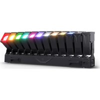
The professional show lasers of the Luke series are designed in two levels for optimum performance and thus separate power pack and fan from the optical components. They feature high-speed 30 Kpps galvos @ 8° ILDA, a 60° scan range and 128 presets that produce impressive graphic projections with crystal clear, razor-sharp beams. The Luke lasers have an ILDA interface with 25-pin D-sub connectors for computer control, 3-pin input and outputs to the DMX control in 11-channel and 4-channel modes and a sensitivity adjustable microphone for sound control. Furthermore, they can be operated as master, slave or in standalone mode. The rugged and lightweight aluminium housing is equipped with a key switch against unauthorised use, a bright display with four buttons for manual control and Neutrik powerCON power connections. A low noise fan ensures low operating temperatures, and to protect the public, the lasers of the Luke series boast a Scan Fail Safety System.
NOTE: The Luke lasers and Ioda series models are equipped with identical presets and are compatible with master-and-slave operation. Using switchable inversion, the master-and-slave arrangement is capable of producing even more impressive laser shows.
LUKE 400RGY
The LUKE 400 RGY boasts a power output of 400 mW, as well as diodes and DPSS lasers for the colours red, green and yellow. The beam diameter is 3 mm with an extremely low divergence of 2 mrad.
LUKE 700RGB
The LUKE 700 RGB boasts diodes and DPSS lasers for the colours red, green and blue and a power output of 700 mW. The beam diameter is 3 mm with a maximum divergence of 2 mrad.
LUKE 1000RGB
The LUKE 1000 RGB boasts a high power output of 1,000 mW and is equipped with diode and DPSS lasers for the colours red, green and blue. The beam diameter is 3 mm with an extremely low divergence of 2 mrad. The red 638 nm diode achieves a significantly better visibility than a conventional 650 nm diode and makes the LUKE 1000 RGB the ideal choice for highly professional laser shows.
• Professional show laser
- Two-level design for superior optical performance
• High-speed 30 Kpps galvoscanner @ 8° ILDA
• 128 impressive presets
- Accurate beams with extremely low divergence for razor-sharp projections
• Control via ILDA, DMX and sound as well as automatic control
• Master, Slave and Standalone operation
- Display with 4 function buttons for easy manual adjustment
- Scan Fail Safety System (prevents leaking of dangerous stray beams)
- Neutrik powerCON power input and output
- Rugged aluminium housing with low-noise fan and key switch
DE Einführung
natural_image
Exterior view of a modern industrial laser unit (no signage or text visible on body)
1 MOUNTING BRACKET / MONTAGEBÜGEL / SUPPORT DE MONTAGE / SOPORTE DE MONTAJE / UCHWYT MONTAŻOWY / STAFFA DI MONTAGGIO
EN Mounting bracket with 2 locking screws.
DE Montagebügel mit 2 Feststellschrauben.
FR Support de montage, avec deux vis de fixation.
ES Soporte de montaje con 2 tornillos de bloqueo.
PL Uchwyt montażowy z 2 śrubami ustalającymi
IT Staffa di montaggio con 2 viti di arresto.
2 OUTLET APERTURE FOR THE LASER BEAMS / AUSTRITTSÖFFNUNG FÜR DIE LASERSTRAHLEN / OUVERTURE POUR LE PASSAGE DU RAYON LASER / ABERTURA DE SALIDA PARA EL LÁSER / OTWÓR WYJŚCIOWY DLA WIĄZKI LASEROWEJ / PUNTO DI EMISSIONE PER I FASCI LASER
EN Under no circumstances should you look into the exiting laser beam. Risk of injury and blindness!
DE Unter keinen Umständen in den austretenden Laserstrahl blicken. Verletzungs- und Erblindungsgefahr!
FR Ne regardez jamais le rayon laser sortant. Danger de blessure ou d'aveuglement!
ES En ningún caso mire directamente al haz láser. ¡Existe peligro de lesiones y ceguera!
PL Pod żadnym pozorem nie patrzeć na wiązkę laserową. Grozi uszkodzeniem ciała i wzroku!
IT Non fissare mai in nessun caso lo sguardo sul fascio laser emesso: pericolo di lesione e accecamento!
3 MAINS INPUT SOCKET / NETZEINGANGSBUCHSE / EMBASE ENTRÉE SECTEUR / ENTRADA ELÉCTRICA / GNIAZDO SIECIOWE WEJŚCIOWE / PRESA DI INGRESSO
EN Neutrik powerCON mains socket. An appropriate power cord is included in the delivery.
DE Neutrik powerCON Netzbuchse. Ein geeignetes Netzkabel befindet sich im Lieferumfang.
FR Embase secteur Neutrik powerCON. Le câble secteur correspondant est livré.
ES Entrada eléctrica por Neutrik powerCON. Se suministra con el cable eléctrico apropiado.
PL Gniazdo zasilania sieciowego Neutrik powerCON. W zestawie znajduje się odpowiedni kabel sieciowy.
IT Presa di rete Neutrik powerCON. In dotazione viene fornito un cavo di rete idoneo.
4 FUSE HOLDER / SICHERUNGSHALTER / PORTE-FUSIBLE / PORTAFUSIBLES / PODSTAWA BEZPIECZNIKA / PORTAFUSIBILI
EN Always replace the fuse only with a fuse of the same type with the same rating (printed on the device). If the fuse blows repeatedly, please contact an authorised service centre.
EN Neutrik powerCON mains output socket for supplying power to other CAMEO products. Make sure that the total current consumption in amperes (A) of all connected devices does not exceed the specified value on the device.
EN On / Off switch for the power supply of the device.
EN Connection socket for the optional emergency stop switch CLLEKS20M with 20 m connection cable. If the emergency stop switch is not used, the supplied jumper plug must be connected to the interlock socket in order to be able to activate the laser.
EN Lock switch for turning the laser effect on and off. In the OFF position, the laser effect is disabled; in the ON position, it is enabled. Two keys are included. Make sure that unauthorised users cannot operate the device, lock the lock switch and remove the associated key.
EN 3-pin male XLR socket for connection of a DMX controller (e.g. DMX mixer).
EN 3-pin female XLR socket for looping through the DMX control signal.
EN ILDA input with 25-pin D-Sub connector for computer control. ILDA software for show programming is not included.
EN 25-pin D-Sub connector for looping through the ILDA control signal.
EN Displays the operating mode and other system settings. The lighting of the LC display can be optionally adjusted in the system settings to permanently on, permanently off, on for 5 seconds, or for 15 seconds.
On the top level of the menu structure, (if necessary, press MODE repeatedly) select the menu item "DMX-512 Mode" using the UP and DOWN buttons and confirm with ENTER. Using the UP and DOWN buttons, one of the two available modes 4-channel or 11-channel mode (4CHmode, 11CHmode) can now be selected. Confirm the input with ENTER.
SETTING THE DMX START ADRESS
On the top level of the menu structure, (if necessary, press MODE repeatedly) select the menu item "DMX-512 Address" using the UP and DOWN buttons and confirm with ENTER. Using the UP and DOWN buttons, the DMX start address can now be set as desired (Address 001 - Address 512). Confirm the input with ENTER.

AUTOMATIC MODE
On the top level of the menu structure, (if necessary, press MODE repeatedly) select the menu item "Auto Mode" using the UP and DOWN buttons and confirm with ENTER. Using the UP, DOWN and ENTER buttons, you can select the items in the sub-menus, access lower levels in the menu structure and adjust settings as desired (see menu structure table). Confirm all inputs with ENTER. The characters in the Cartoon category are suitable for projections on surfaces; the programming of the Beam category for use in fog; Mix is a combination of all categories. The speed of the projection movement can be individually adjusted (Speed 01 - 99).

flowchart
graph LR
    A["->AUTO MODE"] --> B["Auto Mode ENTER --> UP/DOWN Cartoon ENTER --> UP/DOWN Animals ENTER --> UP/DOWN Speed 01 - 99"]
    B --> C["Persons ENTER --> UP/DOWN Speed 01 - 99"]
    B --> D["Objects ENTER --> UP/DOWN Speed 01 - 99"]
    B --> E["Mix ENTER --> UP/DOWN Speed 01 - 99"]

MUSIC CONTROL
On the top level of the menu structure, (if necessary, press MODE repeatedly) select the menu item "Sound Mode" using the UP and DOWN buttons and confirm with ENTER. Using the UP, DOWN and ENTER buttons, you can select the items in the sub-menus, access lower levels in the menu structure and adjust settings as desired (see menu structure table). Confirm all inputs with ENTER. The characters in the Cartoon category are suitable for projections on surfaces; the programming of the Beam category for use in fog; Mix is a combination of all categories.
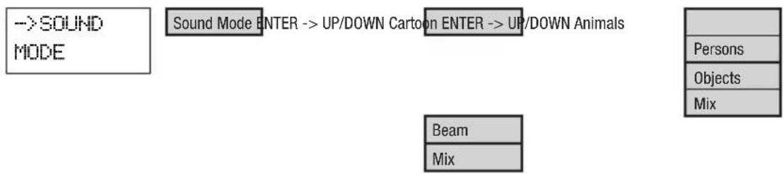
flowchart
graph TD
    A["->SOUND MODE"] --> B["Sound Mode ENTER --> UP/DOWN Cartoon"]
    B --> C["ENTER --> UP/DOWN Animals"]
    C --> D["Beam"]
    C --> E["Mix"]
    F["Persons"] --> G["Objects"]
    G --> H["Mix"]
SYSTEM SETTINGS
On the top level of the menu structure, (if necessary, press MODE repeatedly) select the menu item "Setup" using the UP and DOWN buttons and confirm with ENTER. Using the UP, DOWN and ENTER buttons, you can select the items in the sub-menus, access lower levels in the menu structure and adjust settings as desired (see menu structure table). Confirm all inputs with ENTER.

flowchart
graph TD
    A["Setup ENTER --> UP/DOWN Display ENTER --> UP/DOWN ON"] --> B["Master"]
    B --> C["ENTER --> UP/DOWN ON"]
    C --> D["Laser"]
    D --> E["ENTER --> UP/DOWN Size"]
    E --> F["Colour"]
    F --> G["ENTER --> UP/DOWN RGB"]
    G --> H["RGY"]
    E --> I["InvertX"]
    I --> J["ENTER --> UP/DOWN ON"]
    J --> K["OFF"]
    E --> L["InvertY"]
    L --> M["ENTER --> UP/DOWN ON"]
    M --> N["OFF"]
    A --> O["Default"]
    O --> P["ENTER"]
    P --> Q["Test Pattern"]
    Q --> R["ENTER --> UP/DOWN Scanner 10 - 30KPPS"]
| CLLLUKE700RGB / CLLLUKE1000RGB System Settings - terms and explanations | |||
| Display ON = Display light | s permanently on | ||
| OFF = Display light is permanently off | |||
| 5S = Display light turns off after 5 seconds of inactivity | |||
| 15S = Display light turns off after 15 seconds of inactivity | |||
| Master ON = Master/Slave | mode: DMX signals will be output | ||
| OFF = Master/Slave mode: DMK signals will not be output | |||
| Note on the master/slave mode: Master unit: Master ON | |||
| Slave unit: 4-CH Mode | |||
| Laser Size 10 - 128 = Setting | the maximum size of the laser projection | ||
| Colour = RGB = entire colour spectrum. RGY = red, green and yellow. | |||
| InvertX ON = Movement direction of the X-axis is reversed | |||
| InvertX OFF = Standard movement direction of the X-axis | |||
| InvertY ON = Movement direction of the Y-axis is reversed | |||
| InvertY OFF = Standard movement direction of the Y-axis | |||
| Default = Reset to factory setting | |||
| Test Pattern = Test projection and setting the speed of stepper motors | |||
CLLLUKE400RGY System Settings menu
Setup ENTER -> UP/DOWN Display ENTER -> UP/DOWN ON
| 0FF |
| 5S |
| 15S |
Master
ENTER -> UP/DOWN ON
OFF
Laser
ENTER -> UP/DOWN Size
InvertX
ENTER -> UP/DOWN Size 10 - 128
ENTER -> UP/DOWN
| N |
| OFF |
InvertY
ENTER -> UP/DOWN
| N |
| OFF |
Default
ENTER
Test Pattern
ENTER -> UP/DOWN Scanner 10 - 30KPPS
| CLLLUKE400RGY System Settings - terms and explanations | |||
| Display ON = Display light | is permanently on | ||
| OFF = Display light is permanently off | |||
| 5S = Display light turns off after 5 seconds of inactivity | |||
| 15S = Display light turns off after 15 seconds of inactivity | |||
| Master ON = Master/Slave mode: DMX signals will be output | |||
| Laser Size 10 - 128 = Setting the maximum size of the laser projection | |||
| Default = Reset to factory setting | |||
| Test Pattern = Test projection and setting the speed of stepper motors | |||
DE BEDIENUNG
AUSWAHL DES DMX-MODUS
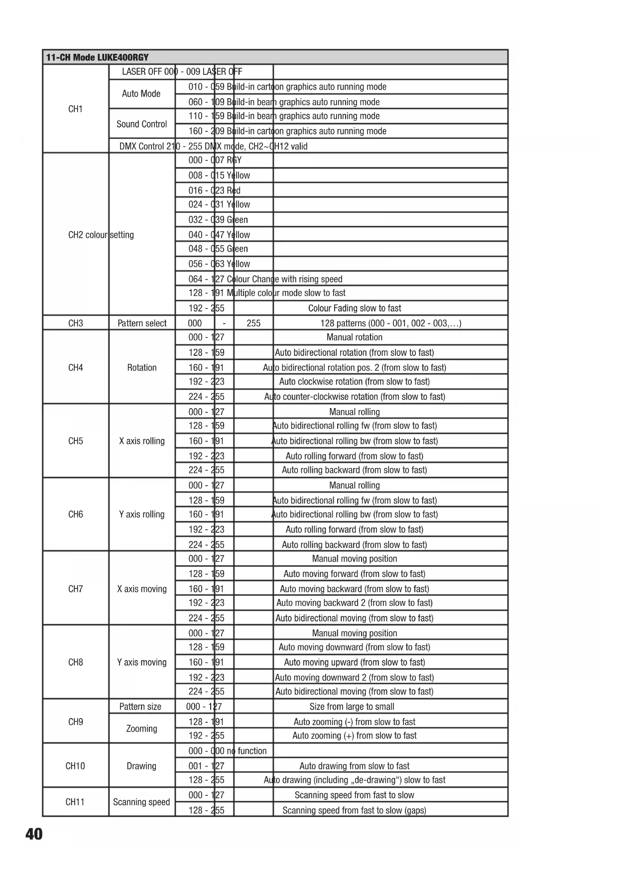
| 11-CH Mode LUKE400RGY | ||||
| CH1 | LASER OFF 000 | - 009 LASER OFF | ||
| Auto Mode | 010 - 059 Build-in cartoon graphics auto running mode | |||
| 060 - 109 Build-in beam graphics auto running mode | ||||
| Sound Control | 110 - 159 Build-in beam graphics auto running mode | |||
| 160 - 209 Build-in cartoon graphics auto running mode | ||||
| DMX Control 210 | - 255 DMX mode, CH2~CH12 valid | |||
| CH2 colour setting | 000 - 007 R&Y | |||
| 008 - 015 Yellow | ||||
| 016 - 023 Red | ||||
| 024 - 031 Yellow | ||||
| 032 - 039 Green | ||||
| 040 - 047 Yellow | ||||
| 048 - 055 Green | ||||
| 056 - 063 Yellow | ||||
| 064 - 127 Colour Change with rising speed | ||||
| 128 - 191 Multiple colour mode slow to fast | ||||
| 192 - 255 | Colour Fading slow to fast | |||
| CH3 | Pattern select | 000 | - | 255 |
| CH4 | Rotation | 000 - 127 | Manual rotation | |
| 128 - 159 | Auto bidirectional rotation (from slow to fast) | |||
| 160 - 191 | Auto bidirectional rotation pos. 2 (from slow to fast) | |||
| 192 - 223 | Auto clockwise rotation (from slow to fast) | |||
| 224 - 255 | Auto counter-clockwise rotation (from slow to fast) | |||
| CH5 | X axis rolling | 000 - 127 | Manual rolling | |
| 128 - 159 | Auto bidirectional rolling fw (from slow to fast) | |||
| 160 - 191 | Auto bidirectional rolling bw (from slow to fast) | |||
| 192 - 223 | Auto rolling forward (from slow to fast) | |||
| 224 - 255 | Auto rolling backward (from slow to fast) | |||
| CH6 | Y axis rolling | 000 - 127 | Manual rolling | |
| 128 - 159 | Auto bidirectional rolling fw (from slow to fast) | |||
| 160 - 191 | Auto bidirectional rolling bw (from slow to fast) | |||
| 192 - 223 | Auto rolling forward (from slow to fast) | |||
| 224-255 | Auto rolling backward (from slow to fast) | |||
| CH7 | X axis moving | 000 - 127 | Manual moving position | |
| 128 - 159 | Auto moving forward (from slow to fast) | |||
| 160 - 191 | Auto moving backward (from slow to fast) | |||
| 192 - 223 | Auto moving backward 2 (from slow to fast) | |||
| 224 - 255 | Auto bidirectional moving (from slow to fast) | |||
| CH8 | Y axis moving | 000 - 127 | Manual moving position | |
| 128 - 159 | Auto moving downward (from slow to fast) | |||
| 160 - 191 | Auto moving upward (from slow to fast) | |||
| 192 - 223 | Auto moving downward 2 (from slow to fast) | |||
| 224 - 255 | Auto bidirectional moving (from slow to fast) | |||
| CH9 | Pattern size | 000 - 127 | Size from large to small | |
| Zooming | 128 - 191 | Auto zooming (-) from slow to fast | ||
| 192 - 255 | Auto zooming (+) from slow to fast | |||
| CH10 | Drawing | 000 - 000 no function | ||
| 001 - 127 | Auto drawing from slow to fast | |||
| 128 - 255 | Auto drawing (including „de-drawing“) slow to fast | |||
| CH11 | Scanning speed | 000 - 127 | Scanning speed from fast to slow | |
| 128 - 255 | Scanning speed from fast to slow (gaps) | |||
| 11-CH Mode LUKE700RGB / LUKE1000RGB | ||||
| CH1 | LASER OFF 000 - 009 LASER OFF | |||
| Auto Mode | 010 - 059 Build-in cartoon graphics auto running mode | |||
| 060 - 109 Build-in beam graphics auto running mode | ||||
| Sound Control | 110 - 159 Build-in beam graphics auto running mode | |||
| 160 - 209 Build-in cartoon graphics auto running mode | ||||
| DMX Control 210 - 255 DMX mode, CH2~CH12 valid | ||||
| CH2 colour setting | 000 - 007 RGB | |||
| 010 - 015 White | ||||
| 016 - 023 Red | ||||
| 024 - 031 Yellow | ||||
| 032 - 039 Green | ||||
| 040 - 047 Cyan | ||||
| 048 - 055 Blue | ||||
| 056 - 063 | Magenta | |||
| 064 - 127 | Colour Change with rising speed | |||
| 128 - 191 | Multiple colour mode slow to fast | |||
| 192 - 255 | Colour Fading slow to fast | |||
| CH3 | Pattern select | 000 - | 255 | 128 patterns (000 - 001, 002 - 003,...) |
| CH4 | Rotation | 000 - 127 | Manual rotation | |
| 128 - 159 | Auto bidirectional rotation (from slow to fast) | |||
| 160 - 191 | Auto bidirectional rotation pos. 2 (from slow to fast) | |||
| 192 - 223 | Auto clockwise rotation (from slow to fast) | |||
| 224 - 255 | Auto counter-clockwise rotation (from slow to fast) | |||
| CH5 | X axis rolling | 000 - 127 | Manual rolling | |
| 128 - 159 | Auto bidirectional rolling fw (from slow to fast) | |||
| 160 - 191 | Auto bidirectional rolling bw (from slow to fast) | |||
| 192 - 223 | Auto rolling forward (from slow to fast) | |||
| 224 - 255 | Auto rolling backward (from slow to fast) | |||
| CH6 | Y axis rolling | 000 - 127 | Manual rolling | |
| 128 - 159 | Auto bidirectional rolling fw (from slow to fast) | |||
| 160 - 191 | Auto bidirectional rolling bw (from slow to fast) | |||
| 192 - 223 | Auto rolling forward (from slow to fast) | |||
| 224-255 | Auto rolling backward (from slow to fast) | |||
| CH7 | X axis moving | 000 - 127 | Manual moving position | |
| 128 - 159 | Auto moving forward (from slow to fast) | |||
| 160 - 191 | Auto moving backward (from slow to fast) | |||
| 192 - 223 | Auto moving backward 2 (from slow to fast) | |||
| 224 - 255 | Auto bidirectional moving (from slow to fast) | |||
| CH8 | Y axis moving | 000 - 127 | Manual moving position | |
| 128 - 159 | Auto moving downward (from slow to fast) | |||
| 160 - 191 | Auto moving upward (from slow to fast) | |||
| 192 - 223 | Auto moving downward 2 (from slow to fast) | |||
| 224 - 255 | Auto bidirectional moving (from slow to fast) | |||
| CH9 | Pattern size | 000 - 127 | Size from large to small | |
| Zooming | 128 - 191 | Auto zooming (-) from slow to fast | ||
| 192 - 255 | Auto zooming (+) from slow to fast | |||
| CH10 | Drawing | 000 - 000 no function | ||
| 001 - 127 | Auto drawing from slow to fast | |||
| 128 - 255 | Auto drawing (including „de-drawing“) slow to fast | |||
| CH11 | Scanning speed | 000 - 127 | Scanning speed from fast to slow | |
| 128 - 255 | Scanning speed from fast to slow (gaps) | |||
DMX TECHNOLOGY / DMX-TECHNIK / TECHNIQUE DMX / TECNOLOGÍA DMX / TECHNIKA DMX / TECNOLOGÍA DMX
EN DMX-512
DMX (Digital Multiplex) is the designation for a universal transmission protocol for communications between corresponding devices and controllers. A DMX controller sends DMX data to the connected DMX device(s). The DMX data is always transmitted as a serial data stream that is forwarded from one connected device to the next via the "DMX IN" and "DMX OUT" connectors (XLR plug-type connectors) that are found on every DMX-capable device, provided the maximum number of devices does not exceed 32 units. The last device in the chain needs to be equipped with a terminator (terminating resistor).

natural_image
Coiled black cable with two connectors, no visible text or symbolsDMX CONNECTION
DMX is the common "language" via which a very wide range of types and models of equipment from various manufacturers can be connected with one another and controlled via a central
controller, provided that all of the devices and the controller are DMX compatible. For optimum data transmission, it is necessary to keep the connecting cables between the individual devices as short as possible. The order in which the devices are integrated in the DMX network has no influence on the addresses. Thus the device with the DMX address 1 can be located at any position in the (serial) DMX chain: at the beginning, at the end or somewhere in the middle. If the DMX address 1 is assigned to a device, the controller "knows" that it should send all data allocated to address 1 to this device regardless of its position in the DMX network.
SERIAL CONNECTION OF MULTIPLE LIGHTS
- Connect the male XLR connector (3-pin or 5-pin) of the DMX cable to the DMX output (female XLR socket) of the first DMX device (e.g. DMX-Controller).
- Connect the female 3-pin XLR connector of the DMX cable connected to the first projector to the DMX input (male 3-pin socket) of the next DMX device. In the same way, connect the DMX output of this device to the DMX input of the next device and repeat until all devices have been connected. Please note that as a rule, DMX devices are connected in series and connections cannot be shared without active splitters. The maximum number of DMX devices in a DMX chain should not exceed 32 units.
The Adam Hall 3 STAR, 4 STAR, and 5 STAR product ranges include an extensive selection of suitable cables.
DMX CABLES
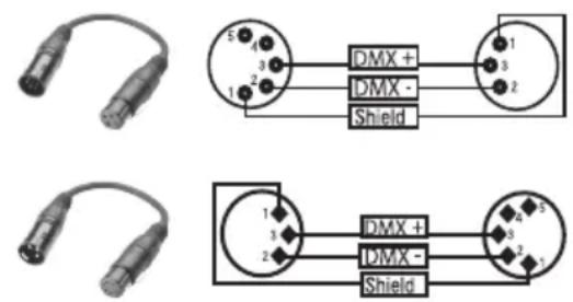
When fabricating your own cables, always observe the illustrations on this page. Never connect the shielding of the cable to the ground contact of the plug, and always make certain that the shielding does not come into contact with the housing of the XLR plug. If the shielding is connected to the ground, this can lead to short-circuiting and system malfunctions.
Pin Assignment
DMX cable with 3-pin XLR connectors: DMX cable with 5-pin XLR connectors (pin 4 and 5 are not used):

flowchart
graph LR
    A["1"] --> B["Shield"]
    C["3"] --> B
    D["2"] --> B
    B --> E["1"]
    B --> F["3"]
    B --> G["2"]

DMX TERMINATORS (TERMINATING RESISTORS)
To prevent system errors, the last device in a DMX chain needs to be equipped with a terminating resistor (120 ohm, 1/4 Watt).
3-pin XLR connector with a terminating resistor: K3DMXT3
5-pin XLR connector with a terminating resistor: K3DMXT5
Pin Assignment
3-pin XLR connector: 5-pin XLR connector:


DMX ADAPTER
The combination of DMX devices with 3-pin connectors and DMX devices with 5-pin connectors in a DMX chain is possible with suitable adapters.
Pin Assignment
DMX Adapter 5-pin XLR male to 3-pin XLR female: K3DGF0020
Pins 4 and 5 are not used.
Pin Assignment
DMX Adapter 3-pin XLR male to 5-pin XLR female: K3DHM0020
Pins 4 and 5 are not used.
DE DMX-512
natural_image
Coiled black cable with two connectors and a terminal connector (no text or symbols visible)DMX-VERBINDUNG:
natural_image
Coiled black cable with two connectors and a terminal connector (no text or symbols visible)PROTOCOLE DMX
natural_image
Coiled black cable with two connectors and a terminal connector (no text or symbols visible)natural_image
Coiled black cable with two connectors and a connector pin (no text or symbols visible)ZŁĄCZE DMX:
IT DMX512
natural_image
Coiled black cable with two connectors and a terminal connector (no text or symbols visible)COLLEGAMENTO DMX:
EN
Model Name: CLLLUKE400RGY CLLLUKE700RGB CLLLUKE1000RGB
| Product Type: effect projector | |||
| Type: laser | |||
| Colour Spectrum: Red 650 nm | Green 532 nm | Red 650 nm | Red 638 nm |
| Green 532 nm | Green 532 nm | ||
| Blue 447 nm | Blue 447 nm | ||
| Number of Diodes: 1 x red, 1 x green 1 x red, 1 x green, 1 x blue 1 x red, 1 x green, 1 x blue | |||
| Type of Diodes: Red 300 mW (laser diode) | Green 100 mW (DPSS) | Red 300 mW (laser diode) | Red 250 mW (laser diode) |
| Green 80 mW (DPSS laser) | Green 150 mW (DPSS laser) | ||
| Blue 300 mW (laser diode) | Blue 600 mW (laser diode) | ||
| Stepper Motors X / Y: 10 - 30 kpps | |||
| Beam Angle: 60° | |||
| Laser Class: 3B 4 4 | |||
| Beam Data: | Approx. 3 mm/2 mrad | Approx. 3 mm/2 mrad | Approx. 3 mm/1.5 mrad |
| Laser Shutdown (safety function): | Key switch, interlock connection, Scan Fail Safety System | ||
| ILDA Input: | 25-pin D-SUB connector male | ||
| ILDA Output: | 25-pin D-SUB connector female | ||
| DMX Protocol: | DMX512 | ||
| DMX Input: | 3-pin XLR male | ||
| DMX Output: | 3-pin XLR female | ||
| DMX Mode: | 4-channel, 11-channel | ||
| DMX Functions: | Auto program, Sound program, 128 animations, laser, X-motor, Y-motor | ||
| Standalone Functions: | Auto program, Sound program, 128 animations, master/slave function | ||
| Controls: | Mode, Enter, Up, Down, Sound Sensitivity | ||
| Display Elements: | backlit, 2-line LC display, 4 indicator LEDs | ||
| Power Connector: | Neutrik powerCON input and output | ||
| Power Out Maximum Connection Value: | 4A | ||
| Operating Voltage: | 100 V - 240 V AC, 50 - 60 Hz | ||
| Power Consumption: | 75 W | 75 W | 100 W |
| Fuse: | F2AL / 250 V | ||
| Operating Temperature: | 10°C - 40°C | ||
| Relative Humidity: | 10% to 70%, non-condensing | ||
| Housing Material: | metal | ||
| Housing Colour: | black | ||
| Housing Cooling: | fan | ||
| Dimensions (W x H x D, excluding bracket): | 215 x 157 x 225 mm | ||
| Weight: | 4.4 kg 4.5 kg | 4.5 kg | |
Other Features:
Power cable, adjustable mounting bracket, safety eyelet, jumper plug, key included, emergency stop switch optional
You can find our current warranty conditions and limitations of liability at: http://www.adamhall.com/media/shop/downloads/documents/manufacturersdeclarations.pdf. To request warranty service for a product, please contact Adam Hall GmbH, Daimler Straße 9, 61267 Neu Anspach / Email: Info@adamhall.com / +49 (0)6081 / 9419-0.

CORRECT DISPOSAL OF THIS PRODUCT
(valid in the European Union and other European countries with a differentiated waste collection system) This symbol on the product, or on its documents indicates that the device may not be treated as household waste. This is to avoid environmental damage or personal injury due to uncontrolled waste disposal. Please dispose of this product separately from other waste and have it recycled to promote sustainable economic activity. Household users should contact either the retailer where they purchased this product, or their local government office, for details on where and how they can recycle this item in an environmentally friendly manner. Business users should contact their supplier and check the terms and conditions of the purchase contract. This product should not be mixed with other commercial waste for disposal.
natural_image
Stylized white letter 'J' on black background, enclosed in a rounded square frame (no text or symbols)WWW.CAMEOLIGHT.COM


- LUKE SERIES
- EN You've made the right choice!
- FOR EQUIPMENT THAT CONNECTS TO THE POWER MAINS:
- CAUTION
- CAUTION:
- CAUTION! HIGH VOLUMES IN AUDIO PRODUCTS!
- CAUTION! IMPORTANT INFORMATION ABOUT LIGHTING PRODUCTS!
- CAUTION! IMPORTANT INFORMATION ABOUT LASER PRODUCTS!
- LUKE 400RGY
- LUKE 700RGB
- LUKE 1000RGB
- DE Einführung
- MOUNTING BRACKET / MONTAGEBÜGEL / SUPPORT DE MONTAGE / SOPORTE DE MONTAJE / UCHWYT MONTAŻOWY / STAFFA DI MONTAGGIO
- OUTLET APERTURE FOR THE LASER BEAMS / AUSTRITTSÖFFNUNG FÜR DIE LASERSTRAHLEN / OUVERTURE POUR LE PASSAGE DU RAYON LASER / ABERTURA DE SALIDA PARA EL LÁSER / OTWÓR WYJŚCIOWY DLA WIĄZKI LASEROWEJ / PUNTO DI EMISSIONE PER I FASCI LASER
- MAINS INPUT SOCKET / NETZEINGANGSBUCHSE / EMBASE ENTRÉE SECTEUR / ENTRADA ELÉCTRICA / GNIAZDO SIECIOWE WEJŚCIOWE / PRESA DI INGRESSO
- SETTING THE DMX START ADRESS
- AUTOMATIC MODE
- MUSIC CONTROL
- SYSTEM SETTINGS
- CLLLUKE400RGY System Settings menu
- DE BEDIENUNG
- AUSWAHL DES DMX-MODUS
- DMX TECHNOLOGY / DMX-TECHNIK / TECHNIQUE DMX / TECNOLOGÍA DMX / TECHNIKA DMX / TECNOLOGÍA DMX
- EN DMX-512
- DMX CONNECTION
- SERIAL CONNECTION OF MULTIPLE LIGHTS
- DMX CABLES
- Pin Assignment
- DMX TERMINATORS (TERMINATING RESISTORS)
- DMX ADAPTER
- DE DMX-512
- DMX-VERBINDUNG:
- PROTOCOLE DMX
- ZŁĄCZE DMX:
- IT DMX512
- COLLEGAMENTO DMX:
- CORRECT DISPOSAL OF THIS PRODUCT
Brand : Cameo
Model : LUKE 700 RGB
Category : Laser pointer