
LUCIA 60170 - Receiver Lab Gruppen - Free user manual and instructions
Find the device manual for free LUCIA 60170 Lab Gruppen in PDF.
| Product Type | Audio Amplifier / Receiver |
| Brand | Lab Gruppen |
| Model | LUCIA 60170 |
| Power Supply | 100-240 V, 50/60 Hz |
| Output Power | 60 W RMS (70 V model) |
| Load Impedance | 2, 4, 8 or 16 ohms (low-impedance models); 70/100 V (high-impedance models) |
| Audio Inputs | Balanced (Euroblock 3-pin), Unbalanced (RCA) |
| Speaker Outputs | Euroblock connectors, up to 4 mm² (12 AWG) |
| Connectivity | USB (mini B), GPIO (Euroblock 6-pin), RS-232 |
| DSP Functions | Mix matrix, filters, limiter, configurable presets |
| Remote Control | GPIO for volume, standby, status; RS-232 for third-party control |
| Standby | Automatic after 20 minutes without signal; wake in 2 seconds |
| Cooling | Smart fan, speed control based on load |
| Mounting | Wall mount (brackets included) or rack shelf (optional kit) |
| LED Indicators | Standby/service LED (orange/green), signal/limiter/clip (green/orange/red) |
| Protection | Voltage limiter, thermal protection, short circuit, power supply fault |
| Compliance | FCC Class B, Canada NMB-003, electrical safety |
| Maintenance | Clean with dry cloth; do not block ventilation openings |
| Included Accessories | USB mini B cable, wall brackets, Torx bolts, IEC power cord |
| Operating Temperature | 0 °C to 40 °C |
Frequently Asked Questions - LUCIA 60170 Lab Gruppen
User questions about LUCIA 60170 Lab Gruppen
0 question about this device. Answer the ones you know or ask your own.
Ask a new question about this device
Download the instructions for your Receiver in PDF format for free! Find your manual LUCIA 60170 - Lab Gruppen and take your electronic device back in hand. On this page are published all the documents necessary for the use of your device. LUCIA 60170 by Lab Gruppen.
USER MANUAL LUCIA 60170 Lab Gruppen
Compact installation amplifiers

LUCIA 60/2
LUCIA 120/2
LUCIA 240/2
LUCIA 60/2M
LUCIA 120/2M
LUCIA 240/2M
LUCIA 60/1-70
LUCIA 120/1-70
LUCIA 240/1-70
LAB.GRuppen
Quick Start Guide
2
Contents
4 English - Quick start guide
9 中文 快速入门指南
14日本語 イイクスロー・ガイド
19 François - Guide de prise en main
24 Deutsch - Das Wichtigste in Kürze
29 Espanol-Guia de Inicio Rápido
Introduction
The information contained in this Quick Start Guide (QSG) is sufficient for proper installation of LUCIA amplifiers, and for configuration of settings in many basic applications. Please refer to the full Operation Manual for detailed information on maintenance, cooling requirements, warranty, and configuration for complex installations.
This QSG also provides an overview of the DSP features offered in the LUCIA and a brief explanation of use with the default DSP preset, which is appropriate for many typical applications. It also includes instructions on downloading the Windows-based PC editor software which is required for custom configuration of DSP features. Advanced users familiar with software-based DSP configuration will find the PC editor highly intuitive, and may not require further information. All other users should consult the detailed information available in the full Operation Manual.
The full Operation Manual is available for download in PDF format from www.labgruppen.com/support.
Important safety instructions
- Read these instructions.
- Keep these instructions
- Heed all warnings.
- Follow all instructions.
- Do not use this apparatus near water.
- Clean only with a dry cloth.
- Do not block any ventilation openings. Install in accordance with the manufacturer's instructions.
- Do not install near any heat sources such as radiators, heat registers, stoves, or other apparatus (including amplifiers) that produce heat.
- Do not defeat the safety purpose of the polarized or grounding-type plug. A polarized plug has two blades with one wider than the other. A grounding-type plug has two blades and a third grounding prong. The wide blade or the third prong is provided for your safety. If the provided plug does not fit into your outlet, consult an electrician for replacement of the obsolete outlet.
- Protect the power cord from being walked on or pinched, particularly at plugs, convenience receptacles, and the point where they exit from the apparatus.
- Only use attachments/accessories specified by the manufacturer.
- Use only with a cart, stand, tripod, bracket, or table specified by the manufacturer, or sold with the apparatus. When a cart is used, use caution when moving the cart/apparatus combination to avoid injury from tip-over.
- Unplug this apparatus during lightning storms or when unused for long periods of time.
- Refer all servicing to qualified service personnel. Servicing is required when the apparatus has been damaged in any way, such as power-supply cord or plug is damaged, liquid has been spilled or objects have fallen in to the apparatus, the apparatus has been exposed to rain or moisture, does not operate normally, or has been dropped.
C
EU marking:
Manufacturer:
Music Group Innovation DK A/S
Sindalsvej 34
DK-8240 Risskov, Denmark
EU representative:
MUSIC Group Innovation UK Limited
Quay House, City Park Business Village 5 Brindley Road
Old Trafford,
Manchester, M16 9UN
United Kingdom
North America Compliance
This equipment has been tested and found to comply with the limits for a Class B Digital device, pursuant to part 15 of the CC rules.
These limits are designed to provide reasonable protection against harmful interference in residential installations. This equipment generates, uses and can radiate radio frequency energy and, if not installed and used in accordance with the instructions, may cause harmful interference to radio communications. However, there is no guarantee that Interference will not occur in a particular installation. If this equipment does cause harmful interference to radio or television reception, which can be determined by turning the equipment off and on, the user is encouraged to try to correct the interference by one or more of the following measures:
Reorientorrelocatethereceivingantenna.
- Increase the separation between the equipment and receiver.
Connect the equipment into an outlet on a circuit different from that to which the receiver is connected.
Consult the dealer or an experienced radio/TV technician for help.
For customers in Canada
This Class B digital apparatus complies with Canadian
ICES-3(b)
Explanation of graphic symbols

The lightning bolt triangle is used to
alert the user to the presence of
un-insulated "dangerous voltages"
within the unit's chassis that may be
of sufficient magnitude to constitute a
risk of electric shock to humans.

The exclamation point triangle is used to alert
the user to presence of important
operating and service instructions in the
literature accompanying the product.
Warning
To reduce risk of fire or electric shock, do not expose this apparatus to rain or moisture.
Do not expose this system/apparatus to dripping or splashing and ensure that no objects filled with liquids, such as vases, are placed on the apparatus.
This apparatus must be connected to a mains socket outlet with a protective earthing connection.
The mains plug is used as a disconnect device and shall remain readily operable.
To prevent electric shock do not remove top or bottom covers. No user serviceable parts inside. Refer servicing to qualified service personnel.
To completely disconnect this equipment from the AC mains, disconnect the power supply cord plug from the ac receptacle. The mains plug of the power supply cord shall remain readily operable.
Do not install this device in a confined space.
Check the voltage in your area and use the correct type of mains connector.
Please refer to the following table:
| Voltage Line plug (according to standard) | |
| 110-125 V (US) UL817 and CSA C22.2 no 42. | |
| 220-230 V (EUROPE) | CEE 7 page VII, SR section 107-2-D1/IEC 83 page-C4. |
| 240 V (UK) | BS 1363 of 1984. Specification for13 A fused plugs and switched andunswitched socket outlets. |
Unpacking and visual checks
Every Lab.gruppen amplifier is carefully tested and inspected before leaving the factory and should arrive in perfect condition. If any damage is discovered, please notify the shipping carrier immediately. Save the packing materials for the carrier's inspection and for any future shipping.
Installation
Wall mounting - For attaching brackets (marked "B" on the drilling guide) to the wall, please use appropriate means for mounting to a specified load of 3kg minimum on each screw. Ensure that all four screws are secured properly to the wall.
For drywall mounting, use a woodscrew (3.5 mm diameter with 25 mm minimum length) and 4.5 mm drywall plug with specified maximum load of greater than 3 kg (e.g. Molly E22412). This method of mounting is evaluated for North America according to UL/CA60065.
For mounting on surfaces other than drywall, please ensure that the method of mounting is suitable for the wall material. Also ensure that the brackets will be secured to the wall with the appropriate means to ensure similar load condition as specified above.
To attach the wall brackets "B" to your amplifier, please use the supplied 3 mm Torx machine screws.
Rack shelf mounting - The amplifier can be mounted to a rack shelf or similar by means of the three holes in the bottom marked "A" on the drilling guide.
Use a 4 mm diameter machine screw (not supplied), ensuring that the length of the screw is suitable for the thickness of the shelf. The screws used should not penetrate into the amplifier for more than 10 - 20mm after mounting.
Lab.gruppen rack shelf kit - A special dedicated rack mount shelf designed to hold two LUCIA amplifiers is available from Lab.gruppen. It includes all necessary accessories, screws, and mounting instructions.
Cooling
Ensure that there is sufficient open space on at least two ventilating surfaces (top, bottom, front and rear) of the amplifiers to allow for free air flow. Please refer to the Thermal Dissipation Chart in the full Operation Manual when installing large numbers of amplifiers in air conditioned spaces.
LUCIA amplifiers feature intelligent fan control. In low power applications and with good ventilation, the fan will remain off. At moderate power levels, the fan may activate in "whisper mode." The fan will run at full speed only at elevated output levels, when noise will be masked by the louder program.
Operating voltage
LUCIA amplifiers have a universal power supply that operates on AC mains from 100 - 240 V at 50 or 60 Hz. The power receptacle on the rear panel accepts the supplied IEC cord which terminates in a connector appropriate for the country of sale.
Grounding
Signal ground is floating via a resistor to chassis, and therefore grounding (earthing) is automatic. For safety reasons, never disconnect the earth (ground) pin on the AC power cord. Use balanced input connections to avoid hum and interference when longer input cables (more than about 1 m/39") are used.
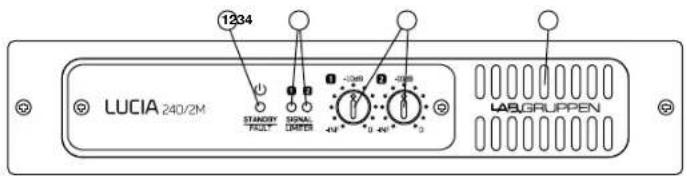
Front panel (all LUCIA models)
The front panel presents the following amplifier status indicators:
1 Standby/On LED indicator - A three-color LED illuminates amber when amplifier is in standby power mode and illuminates green when the amplifier is on. When the amplifier enters Protection mode, the LED flashes red and the speaker outputs are muted. For more information on Protection mode, please refer to the full Operation Manual.
2 Signal present/limit/clip indicators - A three-color LED illuminates to provide channel status information as follows:
Green - Signal is present at the input and the channel is operating normally.
Amber - Limiting is active on the channel. Limiting is engaged when:
The channel reaches the voltage limit as determined by the automatic Voltage Peak Limiter (VPL) setting
Maximum current output is reached
- Mains voltage cannot maintain rail voltage
Red - Channel is clipping either at the input or in DSP.
3 Signal attenuators - A signal attenuator is provided for input channels 1 and 2. Attenuators are adjustable over a range of minus infinity to 0 dB.
Note: In LUCIA constant voltage mono models (60/1-70, 120/1-70 and 240/1-70), the attenuators provide an input select and mixing function by setting the level from each input that goes to the single output channel.
4 Airflow input - Make certain this input is not blocked or covered.
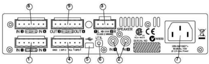
Rear panel: Two output low impedance models
(LUCIA 60/2, 120/2, 240/2, 60/2M, 120/2M, 240/2M)
1 Balanced audio inputs (1 & 2) Connect balanced inputs using 3-pole Euroblock connectors. Correct polarity (+, -) and ground terminations are shown on the rear panel.
2 Unbalanced audio inputs (1 & 2) Connect unbalanced inputs (e.g. local video screen output, CD player) to the RCA (phono) inputs. Note: Balanced and unbalanced inputs are in parallel; only one pair of inputs should be connected at one time.
3 Speaker outputs Connect loudspeakers with nominal impedance of 2,4,8 or 16 ohms. Maximum connector current rating is 41 Arms (exceeding capacity of the amplifier). Cables up to 4mm^2 (12 AWG) can be accommodated. Observe polarity to avoid low frequency cancellation loss.
Note: Bridge mode connection is not supported.
4 GPIO/Remote connector - Connect external control and status monitoring devices using the six-pole Euroblock connector. See "GPIO Configuration" in Set-up and Operation section following.
5 USB port - Connects to external computer for downloading DSP presets. See "DSP/Matrix Configuration" in full Operation Manual. Connection requires cable with a Mini B type connector (Included).
6 UTIL (Utility) switch - Recessed switch places unit in update mode for firmware updates. The switch must be pushed in and held down while the USB connector is being inserted to activate update mode. Refer to the full Operation Manual for more information.
7 AC line input Connect the included IEC power cable.
The following features are located on the rear panel of LUCIA 60/2M, 120/2M and 240/2M only:
8 Balanced audio inputs (3 & 4) Connect balanced inputs using 3-pole Euroblock connectors. Correct polarity (+, -) and ground terminations are shown on the rear panel.
9 Matrix line outputs - Connect balanced line output cable using 3-pole Euroblock connectors Correct polarity (+, -) and ground terminations are shown on the rear panel.

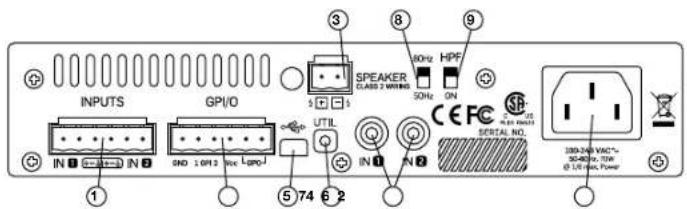
Rear panel: Mono high-impedance models
(LUCIA 60/1-70, 120/1-70 and 240/1-70)
1 Balanced audio inputs (1 & 2) Connect balanced inputs using 3-pole Euroblock connectors. Correct polarity (+, -) and ground terminations are shown on the rear panel.
2 Unbalanced audio inputs (1 & 2) Connect unbalanced inputs (e.g., local video screen output, CD player) to the RCA (phono) inputs. Note: Balanced and unbalanced inputs are in parallel; only one pair of inputs should be connected at one time.
3 Speaker outputs - Connect to loudspeakers in a 70 V or 100 V distributed system. Note that if the transformer has marking for 100 V, then the same total power will be delivered as with 70 V. However, since limiting engages at -3 dB relative to 100 V, the power delivered per loudspeaker will be half of the marking on the loudspeaker transformer. Consequently, taps should be set to twice the desired power.
4 GPIO/Remote connector - Connect external control and status monitoring devices using the six-pole Euroblock connector. See "GPIO Configuration" in Set-up and Operation section following.
5 USB port - Connects to external computer for downloading DSP presets. See "DSP/Matrix Configuration" in full Operation Manual. Connection requires cable with a Mini B type connector (included).
6 UTIL (Utility) switch - Recessed switch places unit in update mode for firmware updates. The switch must be pushed in and hold down while the USB connector is being inserted to activate update mode. Refer to the full Operation Manual for more information.
7 AC line input - Connect the included IEC power cable.
8 High pass frequency - Select 80Hz or 50Hz for high pass cutoff frequency. This filter is in series with what gets configured in the Application Browser software.
9 HPF switch - Select ON or bypass for the high pass filter.
Set-up and Operation
Auto Standby / Power-up
LUCIA amplifiers do not have a power switch. The amplifier will turn on automatically when AC power is connected to the unit; it will go into standby mode if no signal is present at any input for 20 minutes. When in standby, the amplifier will power up in two seconds when a signal above the preset threshold (-54 dBi default) is present at any channel input.
GPIO Configuration: Two Output Low Impedance Models
Default functionality is as described below for General Purpose Inputs and Output (GPIO).
Remote volume control - The default functionality for the GPI is independent control of output volume; please note that this control is in series with the control of from the front panel. There are two ways to do this:
- Connect a GPO from a control device that outputs 0 - 3.3 V for control. Their grounds also need to be connected; see full Operational Manual for further instructions.
- Connect a remote volume control potentiometer per channel to pins 1 through 4 of the GPIO connector as shown below. (The Vcc voltage output is 3.3V ).
Amplifier status - Pins 5 and 6 connect to an internal relay to provide amplifier fault indication. The relay is closed when the amplifier is on and operating normally. The relay opens if a fault in either the output channel(s) or in the power supply interrupts normal operation of one or both channels.
Optional GPIO modes - The Matrix models allow other GPIO functions to be enabled by applying changes to the amplifier firmware. See the full Operation Manual for more information.
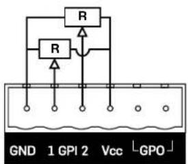
Individual volume control
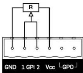
Common volume control
GPIO Configuration: Mono High-Impedance
The Default functionality is as described below for General Purpose Inputs and Output (GPIO).
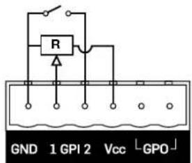
Remote volume control Connect a remote volume control potentiometer to Ground, GPI and Vcc as shown in the diagram following. Volume control is after input mixing. (The Vcc voltage output is 3.3V).
Amplifier wake-up Connect an external contact closure to Ground and GPI2 as shown in the diagram following. Wake-up happens within 0.5 s after contact closure.
Amplifier status - Pins 5 and 6 connect to an internal relay to provide amplifier fault indication. The relay is closed when the amplifier is on and operating normally. The relay opens if a fault in either the output channel(s) or in the power supply interrupts normal operation of one or both channels. Optional GPIO modes - The Matrix models allow other GPIO functions to be enabled by applying changes to the amplifier firmware. See the full Operation Manual for more information.
DSP/Matrix Configuration
The LUCIA models include a mix matrix and a comprehensive suite of DSP features. In nearly all applications for this type of amplifier, the included features eliminate the need for an external mixer or processing unit. Also, the default DSP and matrix configuration allows "out of the box" installation with no further configuration required for many typical applications.
Default preset - The default matrix and DSP configuration is as follows for the M models:
SPEAKER 1 = IN ↑; volume attenuated with GPI 1 (and front knob)
SPEAKER 2 = IN 2; volume attenuated with GPI 2 (and front knob)
Out 3 = In 1 (-6 dB) + In 2 (-6 dB); volume attenuated with GPI 1
Out 4 = In 1 (-6 dB) + In 2 (-6 dB); volume is not affected by GPI
Software download and installation - Very intuitive configuration
software is available that allows selection of which preset to use
(optimized for different loudspeakers) and what dynamics processing to
use. This application is available for free download from
www.labgruppen.com/support.
USB connection - A USB connection is provided for firmware updates and downloading presets to the LUCIA. For complete information please refer to the full Operation Manual.
Custom configuration - Please refer to the full Operation Manual for detailed information on custom configuration of DSP functions using the LUCIA configuration application.
Third-party control - The LUCIA models have a built-in RS-232 serial interface, enabling third-party products to control and monitor LUCIA. For more information on RS-232 serial interface usage, please refer to the "LUCIA Serial Dongle - RS-232 Quick Start Guide", which can be downloaded from http://labgruppen.com/support/download-quick-start-guide
介绍
(LUCIA 60/2,120/2,240/2,60/2M,120/2M,240/2M)
For customers in Canada
This Class B digital apparatus complies with Canadian ICES-003.
| 電圧 | フラガ規格 |
| 110-125 V (US) UL817 and | CSA C22.2 no 42. |
| 220-230 V (EUROPE) | CEE / page VII, SR section 10/7-2-D1/IEC 83 page C4. |
| 240 V (UK) | BS 1363 of 1984. Specification for 13 A fused plugs and switched and unswitched socket outlets. |