
MULTI V URNU48GVLA2 - Water pump LG - Free user manual and instructions
Find the device manual for free MULTI V URNU48GVLA2 LG in PDF.
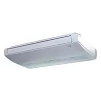


| Product type | Ceiling-mounted indoor air conditioning unit |
| Brand | LG |
| Model | MULTI V URNU48GVLA2 |
| Capacity | Up to 48,000 Btu/h (approximately 14 kW) |
| Dimensions (L x W x H) | Approximately 1655 x 320 x (height not specified) mm |
| Weight | Not specified in the manual |
| Power supply | Single-phase or three-phase depending on installation, requires dedicated circuit breaker |
| Refrigerant | R-410A |
| Refrigerant connection | Flared copper piping, dimensions up to 15.88 mm (gas) and 9.52 mm (liquid) |
| Main functions | Air conditioning, heating, ventilation, dehumidification, wired and wireless remote control |
| Control | Wired (PQRCVSL0) and wireless remote control device |
| Installation | Ceiling-mounted, tilted downward for drainage, requires 4 suspension bolts |
| Drainage | Drain connection with downward slope, left or right orientation |
| Electrical safety | Mandatory grounding, residual current circuit breaker, dedicated circuit |
| Refrigerant safety | Nitrogen leak test after installation, specific tightening torque |
| Maintenance | Regular air filter cleaning, gas leak inspection |
| Spare parts and repairability | Contact dealer or authorized service center for parts and repairs |
| High humidity conditions | Add additional thermal insulation if dew point > 23°C |
Frequently Asked Questions - MULTI V URNU48GVLA2 LG
User questions about MULTI V URNU48GVLA2 LG
0 question about this device. Answer the ones you know or ask your own.
Ask a new question about this device
Download the instructions for your Water pump in PDF format for free! Find your manual MULTI V URNU48GVLA2 - LG and take your electronic device back in hand. On this page are published all the documents necessary for the use of your device. MULTI V URNU48GVLA2 by LG.
USER MANUAL MULTI V URNU48GVLA2 LG
- Please read this installation manual completely before installing the product.
- Installation work must be performed in accordance with the national wiring standards by authorized personnel only.
- Please retain this installation manual for future reference after reading it thoroughly.
TYPE: Ceiling Suspended
TABLE OF CONTENTS
Installation Requirements
Required Parts Required Tools
Introduction. 3
Safety Precautions. 4
Installation
Installation guide map Four type "A" screws & plastic anchors - Connecting cable
Level gauge Screw driver Electric drill Hole core drill Horizontal meter
Selection of the best location 6
Pipes: Gas side
Liquid side
(Refer to Product
Data)
Preparing Work for Installation 6
Indoor Unit Installation 8
Insulation Materials Additional Drain Pipe
Flaring Tool Set - Specified Torque Wrenches (different depending on model No.) Spanner ....Half Union
Preparation of Piping 9 Checking the Drainage.....11 Wiring Connection 11 Side Cover Assembly 13 Installation of Wired Remote Controller 14 Optional Operation of Wired Remote Controller ....16 Dip Switch Setting 17 Group Control Setting 18
Hexagonal Wrench Gas-leak Detector Vacuum Pump Gauge Manifold
Owner's Manual Thermometer
Introduction
Symbols Used in this Manual

This symbol alerts you to the risk of electric shock.

This symbol alerts you to hazards that may cause harm to the air conditioner.

This symbol indicates special notes.
Features
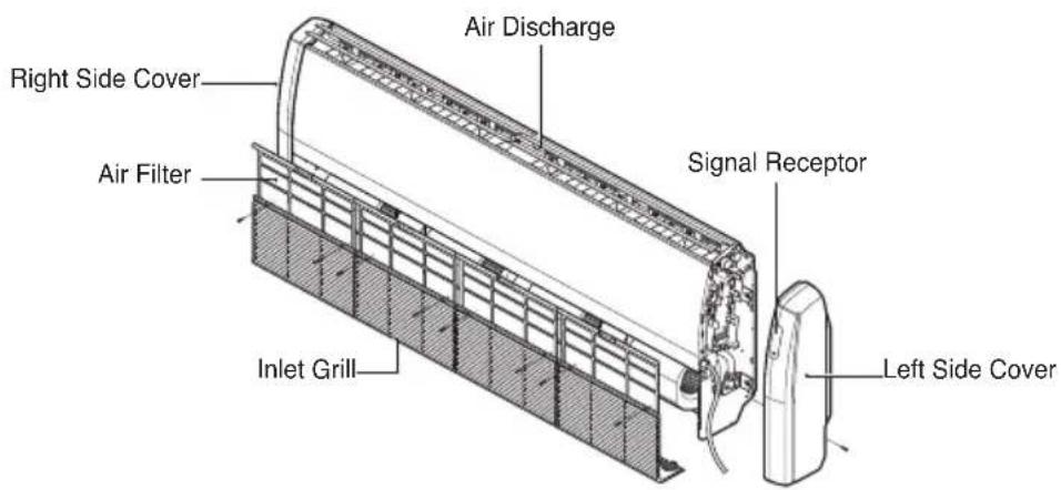
Safety Precautions
To prevent injury to the user or other people and property damage, the following instructions must be followed.
■ Be sure to read before installing the air conditioner. ■ Be sure to observe the cautions specified here as they include important items related to safety. Incorrect operation due to ignoring instruction will cause harm or damage. The seriousness is classified by the following indications.

WARNING
This symbol indicates the possibility of death or serious injury.

CAUTION
This symbol indicates the possibility of injury or damage to properties only.
■ Meanings of symbols used in this manual are as shown below.
| ∅ | Be sure not to do. |
| ! | Be sure to follow the instruction. |

WARNING
■ Installation
Do not use a defective or underrated circuit breaker. Use this appliance on a dedicated circuit.
- There is risk of fire or electric shock.
For electrical work, contact the dealer, seller, a qualified electrician, or an Authorized Service Center.
- Do not disassemble or repair the product. There is risk of fire or electric shock.
Always ground the product.
- There is risk of fire or electric shock.
Install the panel and the cover of the control box securely.
- There is risk of fire or electric shock.
Always install a dedicated circuit and breaker.
- Improper wiring or installation may cause fire or electric shock.
Use the correctly rated breaker or fuse.
- There is risk of fire or electric shock.
Do not modify or extend the power cable.
- There is risk of fire or electric shock.
Do not let the air conditioner run for a long time when the humidity is very high and a door or a window is left open.
- Moisture may condense and wet or damage furniture.
Be cautious when unpacking and installing the product.
- Sharp edges could cause injury. Be especially careful of the case edges and the fins on the condenser and evaporator.
For installation, always contact the dealer or an Authorized Service Center.
- There is risk of fire, electric shock, explosion, or injury.
Do not install the product on a defective installation stand.
- It may cause injury, accident, or damage to the product.
Be sure the installation area does not deteriorate with age.
- If the base collapses, the air conditioner could fall with it, causing property damage, product failure, and personal injury.
Operation
Do not store or use flammable gas or combustibles near the product.
- There is risk of fire or failure of product.
CAUTION
Installation
Always check for gas (refrigerant) leakage after installation or repair of product.
- Low refrigerant levels may cause failure of product.
Install the drain hose to ensure that water is drained away properly.
- A bad connection may cause water leakage.
Keep level even when installing the product.
- To avoid vibration or water leakage.
Do not install the product where the noise or hot air from the outdoor unit could damage the neighborhoods.
- It may cause a problem for your neighbors.
Use two or more people to lift and transport the product.
- Avoid personal injury.
Do not install the product where it will be exposed to sea wind (salt spray) directly.
- It may cause corrosion on the product. Corrosion, particularly on the condenser and evaporator fins, could cause product malfunction or inefficient operation.
If you eat the liquid from the batteries, brush your teeth and see doctor. Do not use the remote if the batteries have leaked.
- The chemicals in batteries could cause burns or other health hazards.
Installation
Read completely, then follow step by step.
Select the best Location
Indoor unit
- Do not have any heat or steam near the unit.
- Select a place where there are no obstacles in front of the unit.
- Make sure that condensation drainage can be conveniently routed away.
- Do not install near a doorway.
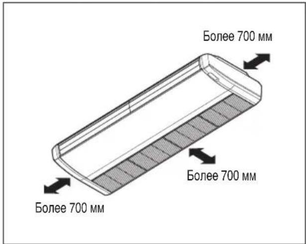
- Ensure that the interval between a wall and the left (or right) of the unit is more than 70cm.
- Use a stud finder to locate studs to prevent unnecessary damage to the wall.
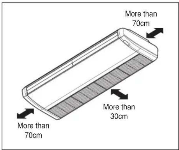
CAUTION: In case that the unit is installed near the sea, the installation parts may be corroded by salt. The installation parts (and the unit) should be taken appropriate anti-corrosion measures.
Preparing Work for Installation
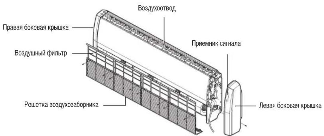
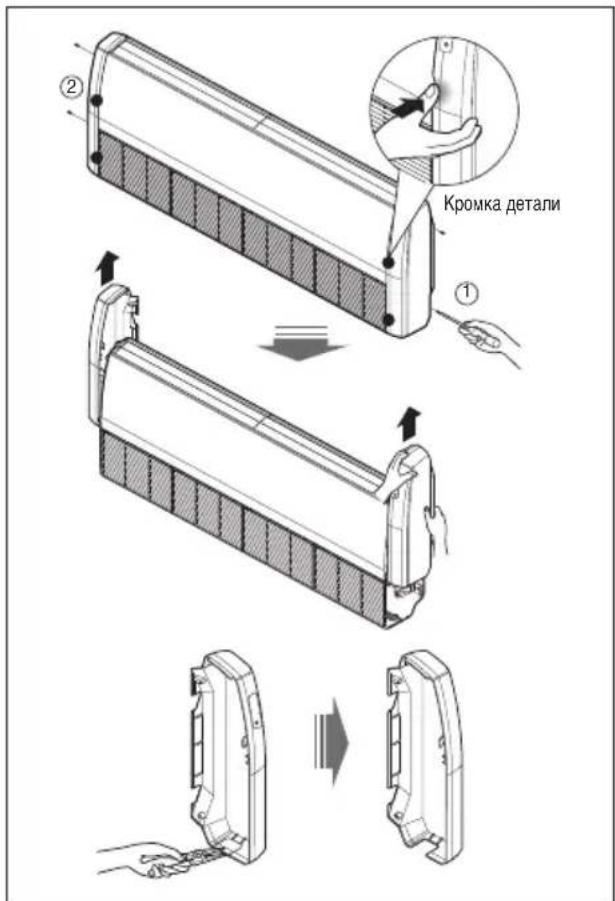
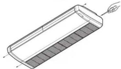
Open side cover
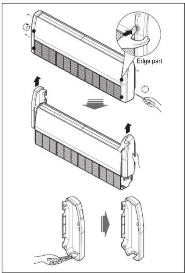
- Remove two screws from side-cover as shown in fig.
- Unlock side-cover from side panel by slightly pulling the edge of side cover.
- Tap the side-cover with your palm on the backside.(Inlet grill side.)
- Hold the side-cover with other hand while tapping to prevent it to fall down.
- The Drain hole is on the left side of the unit and side cover opening is common for drain pipe, connecting pipe and wiring diagram.
- Remove the rubber stopple in the desired drain direction.
- Knock out the pipe hole from the left side-cover with the help or nipper/plier.
- Knock hole on right side-cover only if right side is selected for water drain.
MOUNTING THE ANCHOR NUT AND BOLT
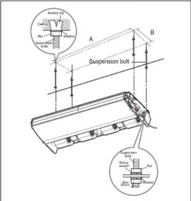
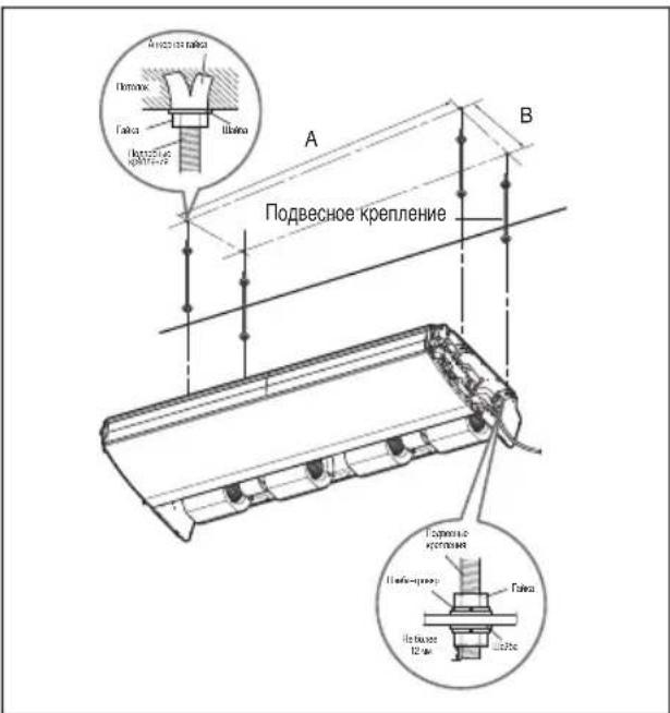
- Prepare 4 suspension bolts. (Each bolt's length should be the same.) Measure and mark the position for the suspension bolts and the piping hole.
- Drill the hole for the anchor nut on the ceiling.
- Insert the nuts and washers onto the suspension bolts to lock the suspension bolts on the ceiling.
- Mount the suspension bolts firmly to the anchor nuts.
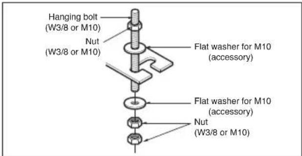
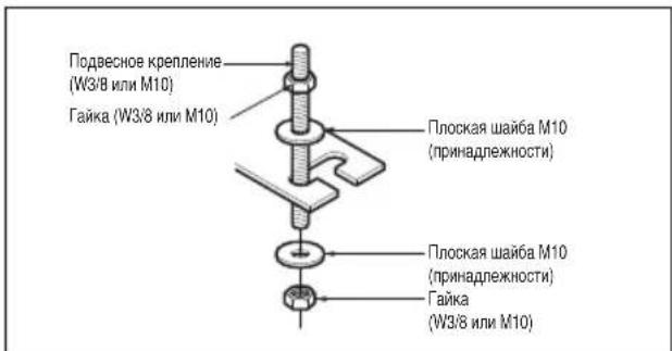
- Secure the hangers onto the suspension bolts (adjust level roughly) using nuts, washers, and spring washers.
- Adjust the level with a level gauge in the left-right and front-back directions by adjusting the suspension bolts.
- Adjust the level in the top-bottom direction by adjusting the suspension bolts. Then the unit will be inclined to the bottom side so as to drain well.
| Dim(mm) Capacity(Btu/h) | A | B |
| 18/24k 855 320 | ||
| 36k 1255 320 | ||
| 48k 1655 320 |

CAUTION
: Tighten the nut and bolt to prevent the unit from falling.
DRILL A HOLE IN THE WALL.
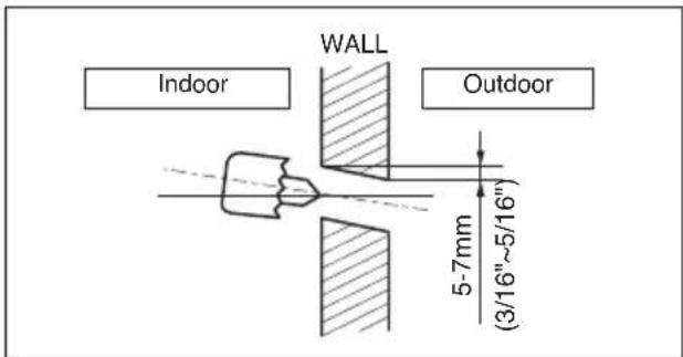
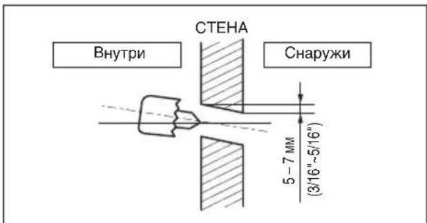
- Drill the piping hole with a 70 mm hole core drill. Drill the piping hole at either the right or the left, with the hole slightly slanted to the outdoor side.
Indoor unit installation
Hang the indoor unit on the suspension bolts as per the following guidelines:
- Lift the indoor unit to a sufficient height.
- Insert the suspended part of the four suspension bolts into the four hangers provided on the side of the main body one by one.
- Lower the indoor unit until the hangers rest on their respective flat washers.
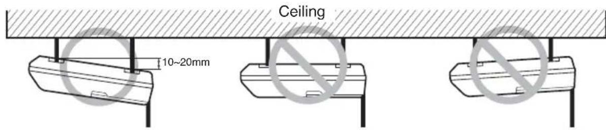
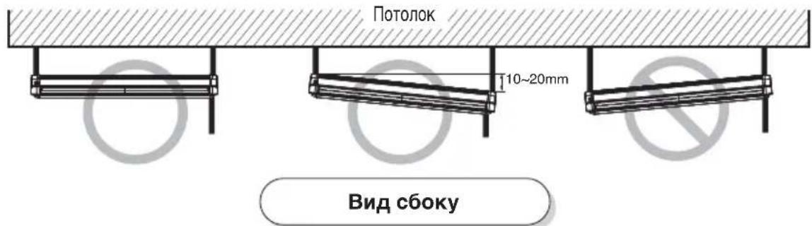
- Adjust the level in the top-down direction by adjusting the suspension bolts. Incline the indoor unit as per the direction provided in the figure.
CAUTION
: Installation Information For Declination
- Install declination of the indoor unit is very important for the drain of the convertible type air conditioner.
- Minimum thickness of the insulation for the connecting pipe shall be 10 mm.
- If the installation plates are fixed to a horizontal line, the indoor unit after installation will be declined to the bottom side.
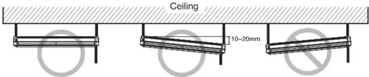
Front view
- The unit must be horizontal or inclined at an angle.
- The inclination should be less than or equal to 1° or between 10 to 20 mm inclined in the drain direction as shown in the figure.
Side view
- The unit must be declined to the bottom side of the unit when installation is finished.
Preparation of Piping
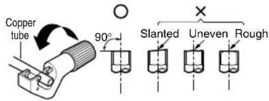
The main cause of gas leakage is a defect in flaring work. Carry out correct flaring work in the following procedure.
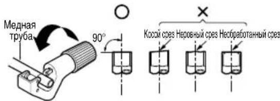
1. Cut the pipes and the cable.
Use the accessory piping kit or pipes purchased locally. Measure the distance between the indoor and outdoor units. Cut the pipes a little longer than the measured distance. Cut the cable 1.5 m longer than the pipe length.
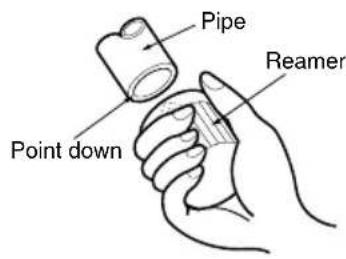
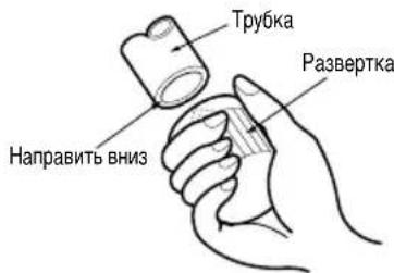
2. Burr removal
- Completely remove all burrs from the cut cross section of the pipe/tube. Point the end of the copper tube/pipe downward while removing burrs to prevent them from falling into the tubing.
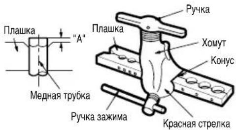
3. Flaring work
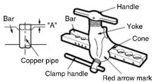
- Perform flaring work using a flaring tool as shown below.
| Indoor unit [kW(Btu/h)] | Pipe " A" | |||
| Gas(mm) | Liquid(mm) | Gas(mm) | Liquid(mm) | |
| <5.6(19,100) | 12.7 | 0.5~0.8 | 0~0.5 | |
| <16.0(54,600) | 15.88 | 0.8~1.0 | 0.5~0.8 | |
| <22.4(76,400) | 19.05 | 0.5~1.0 | 0.5~0.8 | |
Firmly hold the copper tube in a bar (or die) as indicated in the dimensions in the table above.
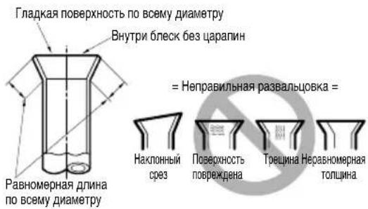
4. Check
Compare the flared work with the figure below. If the flare is defective, cut off the flared section and perform flaring work again.
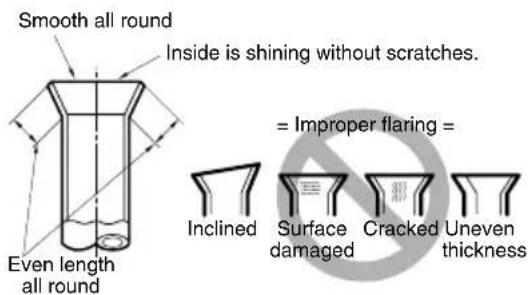
FLARE SHAPE AND FLARE NUT TIGHTENING TORQUE
Precautions when connecting pipes
- See the following table for flare part machining dimensions.
- When connecting the flare nuts, apply refrigerant oil to the inside and outside of the flares and turn them three or four times at first. (Use ester oil or ether oil.)
- See the following table for tightening torque. (Applying too much torque may cause the flares to crack.) After all piping has been connected, use nitrogen to perform a gas leak check.
| pipe size Torque(kgf.m) A(mm) flare shape | ||
| ∅6.35 1.8~2.5 | 8.7~9.1 | |
| ∅9.52 3.4~4.2 | 12.8-13.2 | |
| ∅12.7 5.5~6.6 | 16.2-16.6 | |
| ∅15.88 | 6.3~8.2 19.3-19.7 |

CAUTION
- Always use a charge hose for service port connection. After tightening the cap, check that no refrigerant leaks are present.
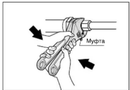
- When loosening a flare nut, always use two wrenches in combination. When connecting the piping, always use a spanner and torque wrench in combination to tighten the flare nut.
- When connecting a flare nut, coat the flare (inner and outer faces) with oil for R410A (PVE) and hand tighten the nut 3 to 4 turns as the initial tightening.
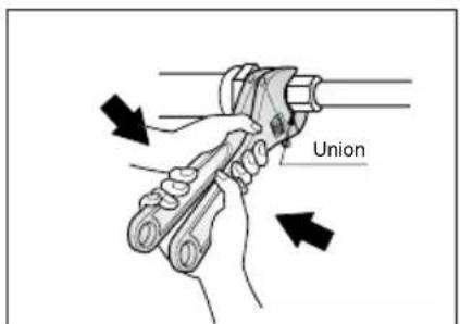
Opening shutoff valve
- Remove the cap and turn the valve counterclockwise with the hexagon wrench.
- Turn it until the shaft stops.
Do not apply excessive force to the shutoff valve. Doing so may break the valve body, as the valve is not a backseat type. Always use the special tool.
- Make sure to tighten the cap securely.
Closing shutoff valve
- Remove the cap and turn the valve clockwise with the hexagon wrench.
- Securely tighten the valve until the shaft contacts the main body seal.
- Make sure to tighten the cap securely.
- For the tightening torque, refer to the table below.
Tightening torque
| Shutoff valve size | Tightening torque N-m(Turn clockwise to close) | |||||
| Shaft(valve body) | Cap(Valve lid) | Service port Flare nut | Gas line piping attached to unit | |||
| Ø6.35 | 5.4-6.6 | Hexagonal wrench 4mm | 13.5-16.5 | 11.5-13.9 | 14-17 | - |
| Ø9.52 | 33-39 | |||||
| Ø12.7 | 8.1-9.9 | 18-22 | 50-60 | |||
| Ø15.88 | 13.5-16.5 | Hexagonal wrench 6mm | 23-27 | 62-75 | ||
| Ø22.2 | 27-33 36 | 44 Hexagonal wrench 10mm | 22-28- | |||
| Ø25.4 | ||||||
HEAT INSULATION
- Use the heat insulation material for the refrigerant piping which has an excellent heat-resistance (over 120°C).
- Precautions in high humidity circumstance:
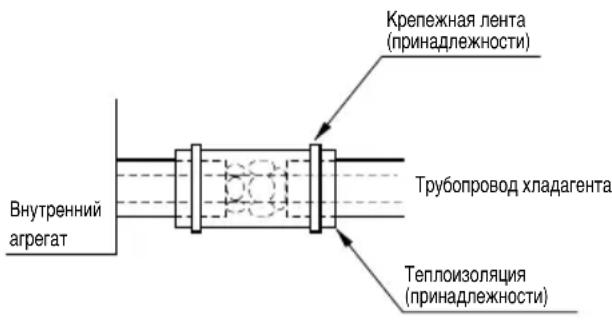
This air conditioner has been tested according to the "ISO Conditions with Mist" and confirmed that there is not any default. However, if it is operated for a long time in high humid atmosphere (dew point temperature: more than 23°C), water drops are liable to fall. In this case, add heat insulation material according to the following procedure:
- Heat insulation material to be prepared... EPDM
(Ethylene Propylene Diene Methylene)-over 120°C
the heat-resistance temperature.
- Add the insulation over 10mm thickness at high humidity environment.
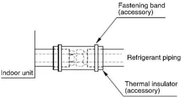
Checking the Drainage
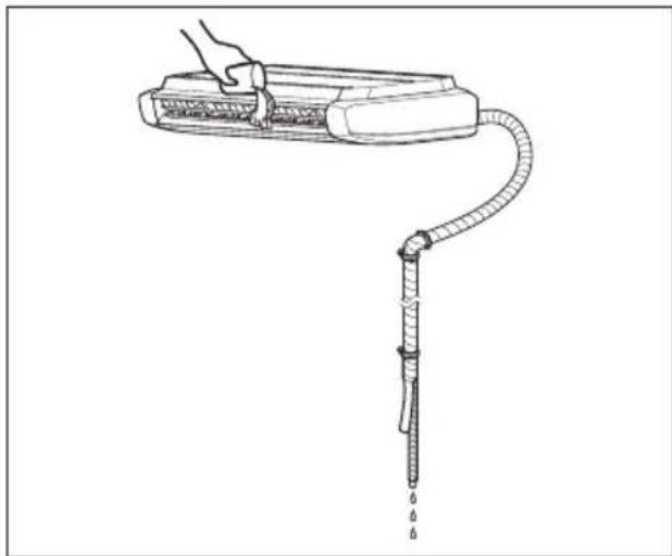
- Set the air direction louvers up-and-down to the position (horizontally) by hand.
To check the drainage.
- Pour a glass of water on the evaporator using a kettle.
- Ensure the water flows through the drain hose of the indoor unit without any leakage and goes out the drain exit.
Drain piping
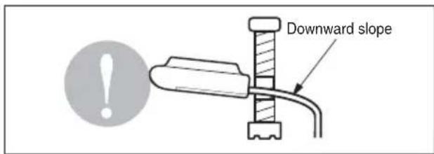
- The drain hose should point downward for easy drain flow.
- Do not make drain piping like the following.

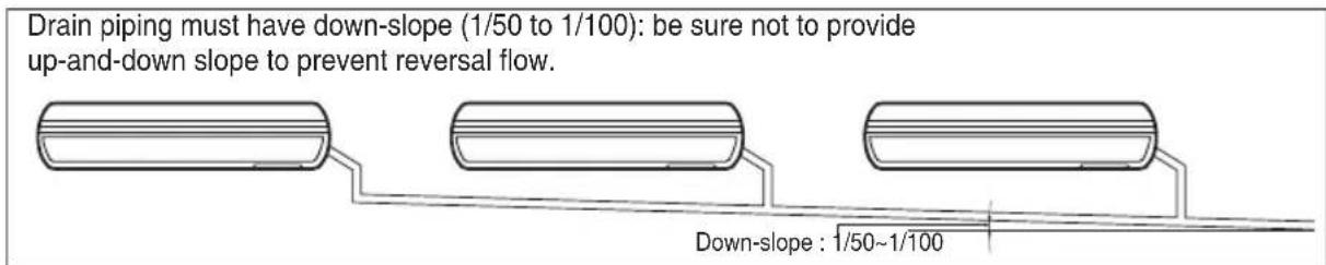
- While merging numerous drain pipes, follow the procedure mentioned below.
Wiring Connection
Connect the wires to the terminals on the control board individually according to the outdoor unit connection.
- Ensure that the color of the wires of outdoor unit and the terminal No. are the same as those of indoor unit respectively.
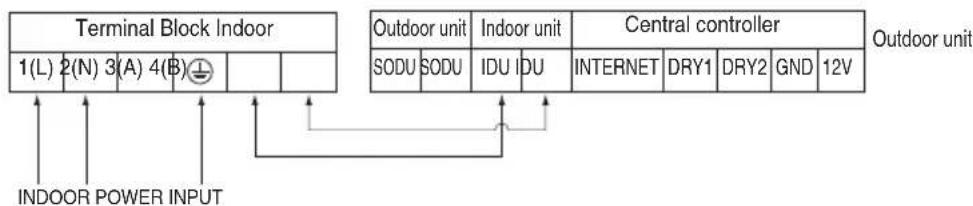

WARNING: Make sure that the screws of the terminal are free from looseness.

CAUTION:
After the confirmation of the above conditions, prepare the wiring as follows:
1) Never fail to have an individual power specialized for the air conditioner. As for the method of wiring, be guided by the circuit diagram posted on the inside of control box cover. 2) Provide a circuit breaker switch between power source and the unit. 3) The screws which fasten the wiring in the casing of electrical fittings are liable to come loose from vibrations to which the unit is subjected during the course of transportation. Check them and make sure that they are all tightly fastened. (If they are loose, it could give rise to burn-out of the wires.) 4) Specification of power source 5) Confirm that electrical capacity is sufficient. 6) Be sure that the starting voltage is maintained at more than 90 percent of the rated voltage marked on the name plate. 7) Confirm that the cable thickness is as specified in the power sources specification. (Particularly note the relation between cable length and thickness.) 8) Never fail to equip a leakage breaker where it is wet or moist. 9) The following troubles would be caused by voltage drop-down.
- Vibration of a magnetic switch, damage on the contact point, fuse breaking, disturbance by the normal function of an overload protection device.
- Proper starting power is not given to the compressor.
HANDOVER
Teach the customer the operation and maintenance procedures, using the operation manual.
air filter cleaning, temperature control, etc.)
WIRED REMOTE CONTROLLER INSTALLATION
- Since the room temperature sensor is in the remote controller, the remote controller box should be installed in a place away from direct sunlight, high humidity and direct supply of cold air to maintain proper space temperature. Install the remote controller about 5ft (1.5m) above the floor in an area with good air circulation at an average temperature.
Do not install the remote controller where it can be affected by:
- Drafts, or dead spots behind doors and in corners.
- Hot or cold air from ducts.
- Radiant heat from sun or appliances.
- Concealed pipes and chimneys.
- Uncontrolled areas such as an outside wall behind the remote controller.
- This remote controller is equipped with a seven segment LED display. For proper display of the remote controller LEDs, the remote controller should be installed properly as shown in Fig.1. (The standard height is 1.2 to 1.5 m from floor level.)
Fig.1 Typical locations for remote controller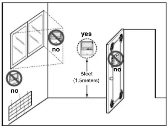
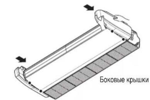
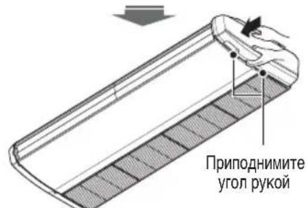
Side Cover Assembly
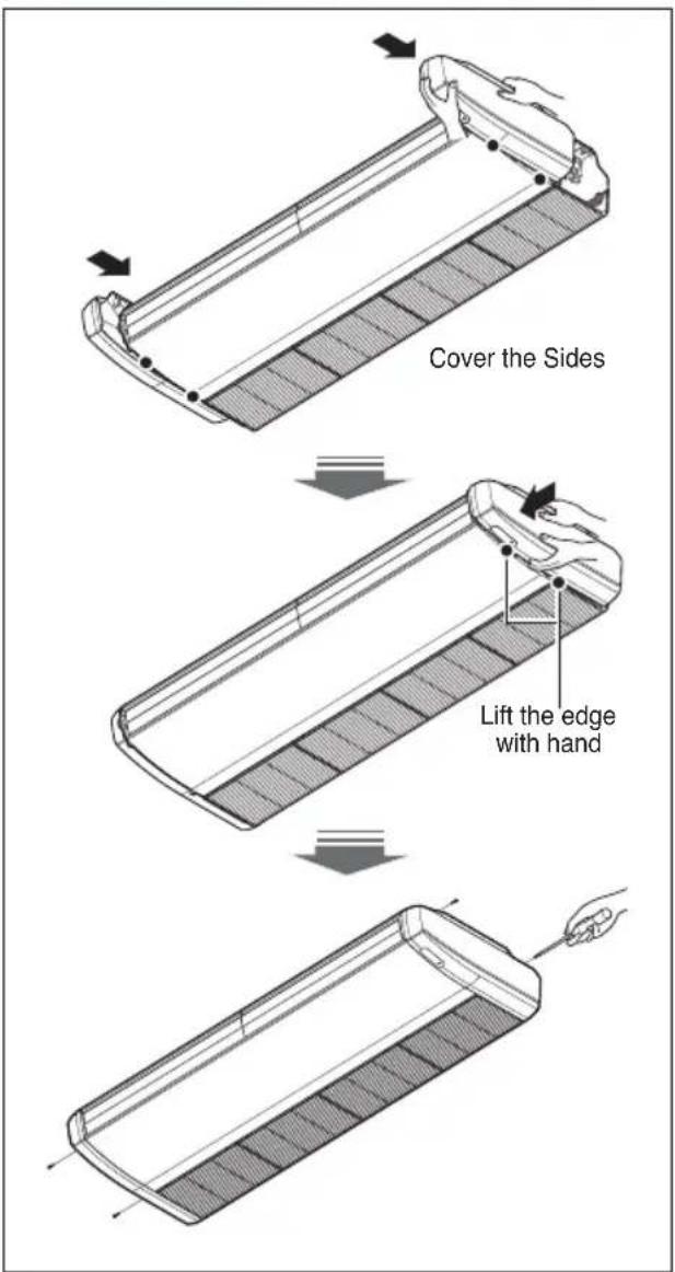
- Cover the sides of main body with side cover as shown in fig.
- Lift slightly the edge of side-cover with hands to fix the cover properly on the panel.
- Push the side-cover from front side (air outlet side) towards the inlet grill side to lock the side cover on the main body.
- Fasten the securing screw.
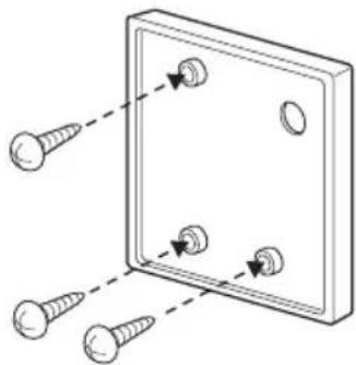
Installation of Wired Remote Controller
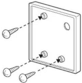
- Please fix tightly using provided screw after placing remote controller setup board on the place where you like to setup.
- Please set it up not to bend because poor setup could take place if setup board bends. Please set up remote controller board fit to the reclamation box if there is a reclamation box.
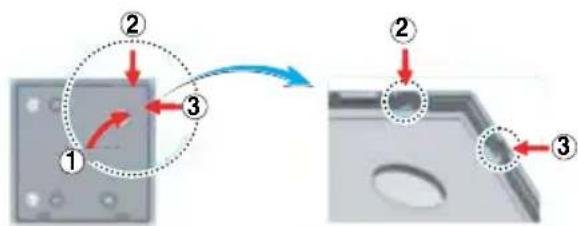
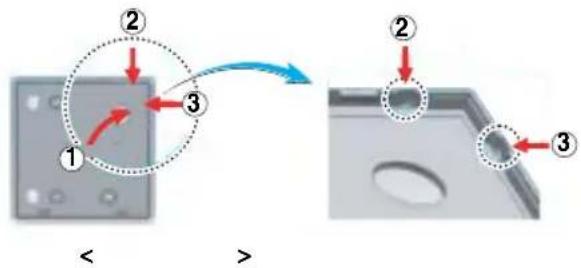
- Can set up Wired remote controller cable into three directions.
- Setup direction: the surface of wall reclamation, upper, right
- If setting up remote controller cable into upper and right side, please set up after removing remote controller cable guide groove.
*Remove guide groove with long nose.
① Reclamation to the surface of the wall ② Upper part guide groove ③ Right part guide groove
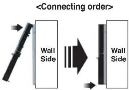
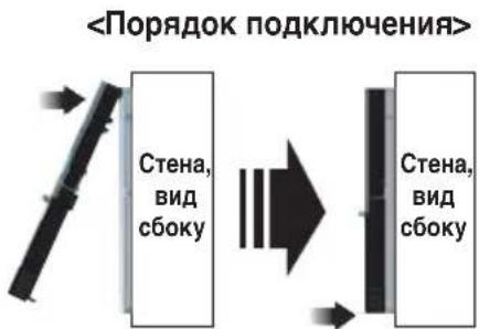
- Please fix the upper part of the remote controller into the setup board attached to the wall surface, as shown in the picture below, and then connect it by pressing the lower part.
- Please connect the remote controller and the setup board without any gaps on the upper, lower, right, and left sides.
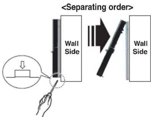
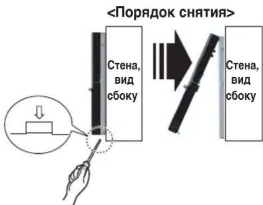
When separating the remote controller from the setup board, as shown in the picture below, insert a screwdriver into the lower separating hole and spin it clockwise to separate the remote controller.
- There are two separating holes. Please separate them one at a time.
- Please be careful not to damage the internal components when separating.
- Please connect the indoor unit and the remote controller using the connection cable.
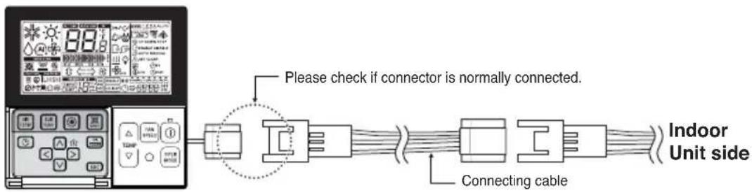
- Please use an extension cable if the distance between the wired remote controller and the indoor unit is more than 10 m.

CAUTION
When installing the wired remote controller, do not bury it in the wall.
(This can cause damage to the temperature sensor.)
Do not install the cable to be 50 m or longer.
(This can cause communication errors.)
- When installing the extension cable, check the connecting direction of the connector on the remote controller side and the product side for correct installation.
- If you install the extension cable in the opposite direction, the connector will not be connected.
- Specification of extension cable: 2547 1007 22# 2 core 3 shield 5 or above.
Name and function of wired remote controller (Accessory)
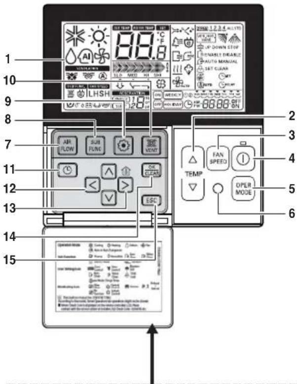
Please attach the inform label inside of the door. Please choose proper language depending on your country.
- Operation indication screen
- Set temperature button
- Fan speed button
Fan speed has 3 steps.
- ON/OFF button
- Operation mode selection button
- Wireless remote controller receiver
- Some products don't receive the wireless signals.
- Air flow button
- Subfunction button
- Function setting button
- Ventilation button
Not working.
- Reservation 12. Up, down, left, right button
To check the indoor temperature, press button.
- Room temperature button
- Displays only the room temperature of the remote controller perception.
- There is no control of room temperature.
- In case of fresh air intake unit, displays only the temperature around remote controller.
- Setting/Cancel button 15.Exit button
* Some functions may not be operated and displayed depending on the product type. * It will display strange value to the room temperature if wired remote controller is not connected.
Model:PQRCVSL0 (Black Color)
PQRCVSLOQW (White Color)
Dip Switch Setting of Indoor unit PCB
| Function Descrip | ption Setting Off Setting On Default | ||||
| SW1 | Communication | N/A (Default) | - | - | Off |
| SW2 | Cycle | N/A (Default) | - | - | Off |
| SW3 | Group Control | Selection of Master or Slave | Master | Slave | Off |
| SW4 | Dry Contact Mode | Selection of Dry Contact Mode | Wired/Wireless remote controllerSelection of Manual or Auto operation Mode | Auto | Off |
| SW5 | Installation | Fan continuous operation | Continuous operation Removall | - | Off |
| SW6 | Heater linkage | N/A | - | - | Off |
| SW7 | Ventilator linkage | Selection of Ventilator link-age | Linkage Removal | Working | Off |
| Vane selection(Console) | Selection of up/down side Vane | Up side + Down side Vane | Up side Vane Only | ||
| Region selection | Selection tropical region | General model | Tropical model | ||
| SW8 | Etc. | Spare | - | - | Off |

CAUTION
For Multi V Models, Dip switch 1, 2, 6, 8 must be set OFF.
Group Control Setting
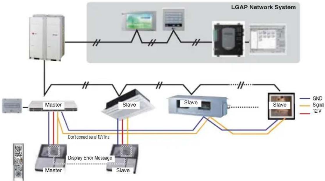
1. Group Control 1
n Wired remote controller 1 + Indoor units

n Dip Switch in PCB
① Master Setting Slave Setting - No. 3 Off - No. 3 On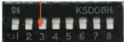
②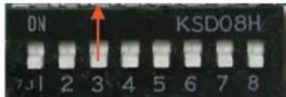
- It is possible to connect up to 16 indoor units (Max) with one wired remote controller.
Set only one indoor unit to Master, set the others to Slave.
- It is possible to connect with every type of indoor unit.
- It is possible to use a wireless remote controller at the same time.
- It is possible to connect with Dry Contact and Central controller at the same time.
- The Master indoor unit is able to recognize Dry Contact and Central Controller only.
- In case of using Central controller and Group controller at the same time, it is possible to connect standard 2-series indoor units or later since Feb. 2009.
- In case of Central controller setting, the Central controller can control indoor units after setting only the address of the master indoor unit.
- Slave indoor unit will be operated like master indoor unit.
- Slave indoor unit cannot be individually controlled by the central controller.
- Some remote controllers cannot operate with both Dry Contact and the central controller at the same time. Please contact us for further information.
- In case of any error occurring at the indoor unit, it will be displayed on the wired remote controller.
Except for the error indoor unit, individual control of an indoor unit is possible.
- In case of Group Control, the following functions can be used.
- Selection of operation options (operation/stop mode/set temperature)
- Control of airflow rate (High/Middle/Low)
- Some functions are not available.
- Master/Slave setting of indoor units can be set using a PCB Dip Switch. * It is possible to connect indoor units manufactured since Feb. 2009. For other cases, please contact LGE.
- It can be the cause of malfunctions when there is no setting of master and slave.
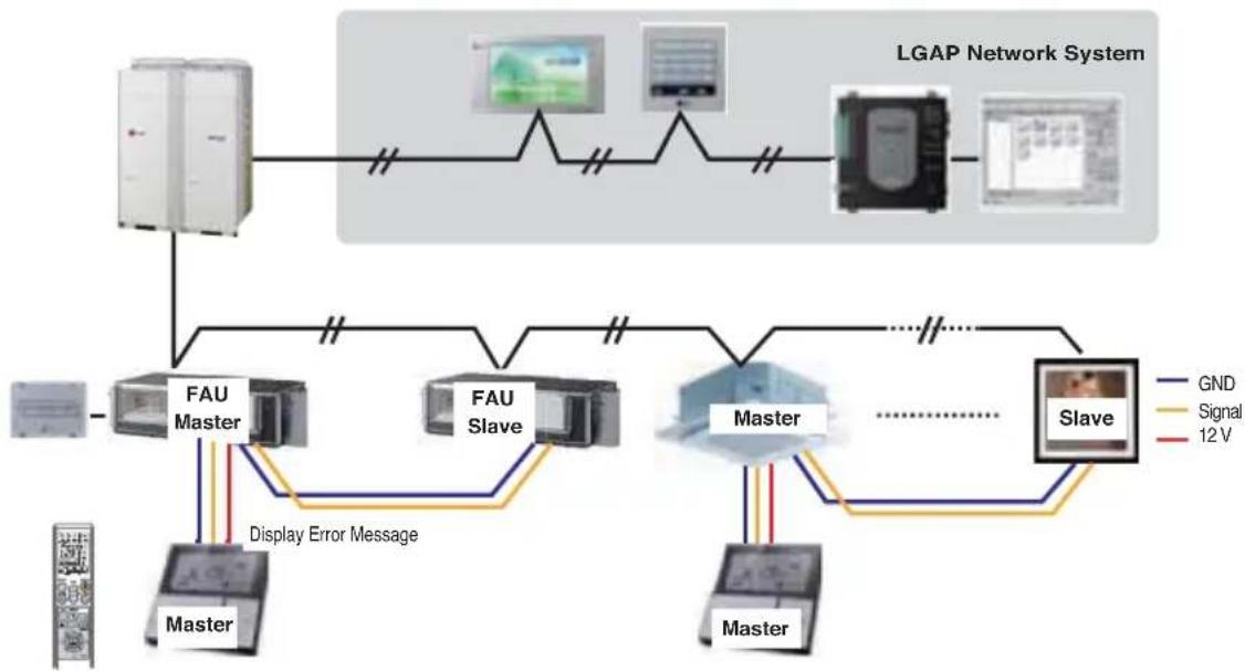
2. Group Control 2
- It is possible to control N indoor units by M wired remote controllers. (M + N ≤ 17 Units)
Set only one indoor unit to Master, set the others to Slave.
Set only one wired remote controller to Master, set the others to Slave.
Other than those, it is same with the Group Control 1.
3. Group Control 3
■ Mixture connection with indoor units and Fresh Air Intake Unit
- In case of connecting with standard indoor unit and Fresh Intake Unit, separate Fresh Air Intake Unit with standard units. (Because setting temperature are different.)
- Other than those, it is same with Group Control 1.
* FAU : Fresh Air Intake Unit Standard: Standard Indoor Unit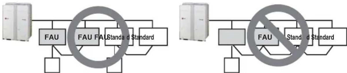
4.2 Remote Control
■ Wired remote controller 2 + Indoor unit 1
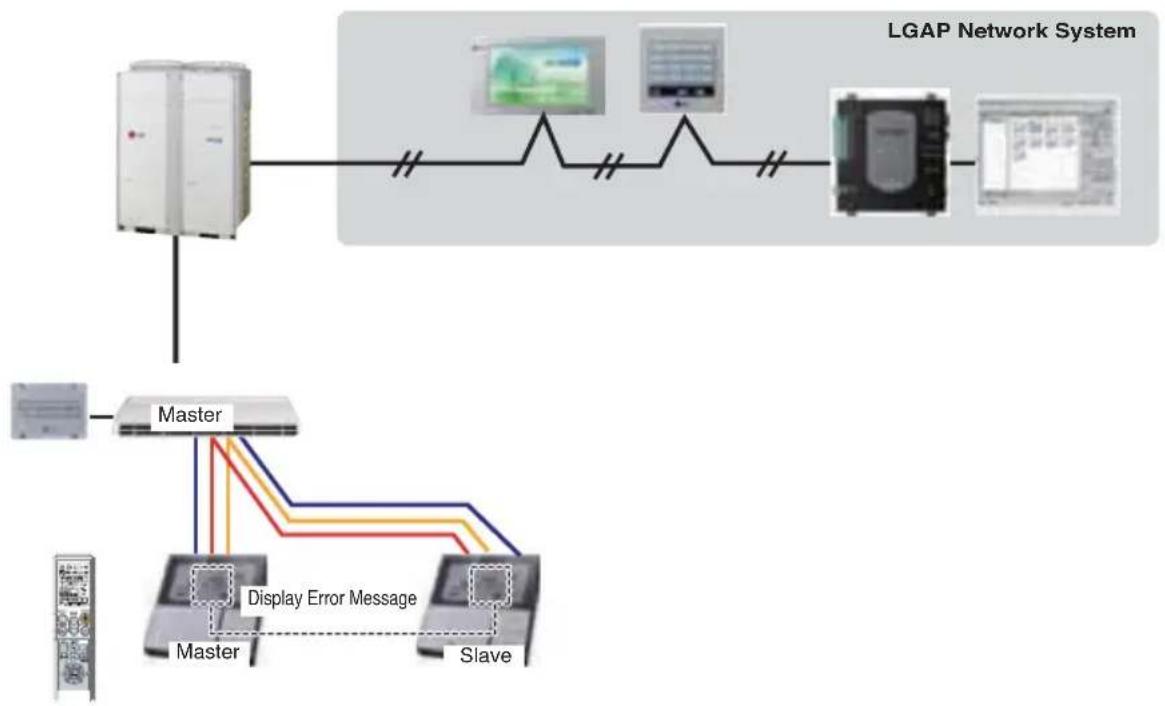
- It is possible to connect two wired remote controllers with one indoor unit.
- Every types of indoor unit is possible to connect two remote controller.
- It is possible to use wireless remote controller at the same time.
- It is possible to connect with Dry Contact and Central controller at the same time.
- In case of any error occurs at indoor unit, display on the wired remote controller.
- There isn't limits of indoor unit function.
- Maximum 2 wired remote controllers can be connected with 1 indoor unit.
5. Accessories for group control setting
It is possible to set group control by using below accessories.
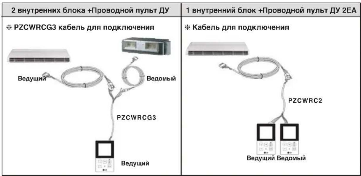
| Indoor unit 2 EA +Wired remote controller | Indoor unit 1 EA +Wired remote controller 2EA |
| * PZCWRCG3 cable used for connection Master r Slave PZCWRCG3 Master r | * PZCWRC2 cable used for connection Master r Slave PZCWRC2 |
Installation of Wired Remote Controller. 14
Optional Operation of Wired Remote Controller ....16
WARNING: In case that the unit is installed near the sea, the installation parts may be corroded by salt. The installation parts (and the unit) should be taken appropriate anti-corrosion measures.
Installation of Wired Remote Controller 14
Optional Operation of Wired Remote Controller 16
DIP switch adjustment ....17
Group control adjustment. 18
CAUTION: In case that the unit is installed near the sea, the installation parts may be corroded by salt. The installation parts (and the unit) should be taken appropriate anti-corrosion measures.
INSTALLATION MANUAL
AIR CONDITIONER
Installation of Wired Remote Controller. 14
Optional Operation of Wired Remote Controller 16
CAUTION: In case that the unit is installed near the sea, the installation parts may be corroded by salt. The installation parts (and the unit) should be taken appropriate anti-corrosion measures.
- No. 3 Off - No. 3 On
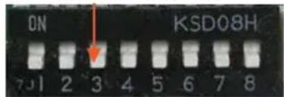
②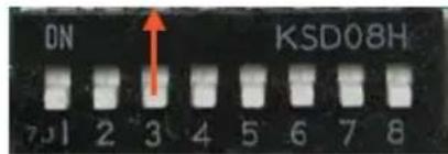
CAUTION: In case that the unit is installed near the sea, the installation parts may be corroded by salt. The installation parts (and the unit) should be taken appropriate anti-corrosion measures.
Selection of installation site 6
Preparatory work before installation 6
Installation of indoor unit...8
Preparation of piping 9
Drainage check. 11
Connection 11
Assembly of side cover 13
Installation of the remote control wire.14
Additional wire remote control options.16
Setting up the DIP switch..17
Setting up group control...18
Required accessories
Installation guide card: Four type "A" screws and plastic anchors, connecting cable pipes: gas and liquid (see information sheet), insulating materials, additional blue pipe
Required tools
Level, screwdriver, electric drill, pipe drill bit, level, set of electric tools, specified wrenches (set depends on model number), wrenches. Half Union
Hex wrench, gas leak detector, vacuum pump, pressure gauge station
Operating/installation instructions for thermometer
Introduction
Symbols used in this manual

This symbol warns of the risk of electric shock.

This symbol warns of the danger of component damage.

This symbol indicates special notes.
Functional nodes
Safety precautions
To prevent injury to the user and other people, as well as material damage, it is necessary to follow the instructions given below.
Before installing the copier, carefully read the manual. Familiarize yourself with the safety precautions listed here, as they contain important points for ensuring safety. Correct operation and adherence to the instructions will prevent damage or injury. The severity of danger is classified as follows.

WARNING
This symbol indicates the possibility of death or serious injury.

CAUTION
This symbol indicates the possibility of injury or only material damage.
The meanings of the symbols used in this manual correspond to those given below.


Do not proceed in the following manner.
Follow the instructions given.

WARNING

Installation
Do not use automatic circuit breakers that are faulty or rated for a lower load. Connect the device only to the nominal voltage.
There is a risk of fire or electric shock.
After completing the electrical work, contact the supplier, seller, or a qualified electrician or an authorized service center.
Do not disassemble or repair the product. There is a risk of fire or electric shock.
Always turn off the product.
There is a risk of fire or electric shock.
Firmly secure the cover of the switch block.
There is a risk of fire or electric shock.
Always install the specified fuse in the automatic circuit breaker.
- Incorrect wiring or installation may cause fire or electric shock.
Use an automatic circuit breaker or fuse of the correct rating.
There is a risk of fire or electric shock.
Do not modify or extend the power cord.
There is a risk of fire or electric shock.
Do not turn on the air conditioner if the door or window is open or if the humidity is very high.
- Condensation may form and damage or ruin furniture.
Be careful when unpacking and installing the product.
Sharp edges may be present. Be especially careful with the edges of the packaging, the sharp edges of the capacitor, and the evaporator.
Installation
For installation, always use the services of the supplier or an authorized center.
There is a risk of fire, electric shock, explosion, or injury.
Do not install the device on an unstable mounting stand.
This may lead to injury, an accident, or damage to the device.
Check that the installation location has not deteriorated over time.
- If the base is damaged, the compressor may fall, causing material damage and also leading to damage to property and injury.
Operation
Do not store or use flammable gas or other flammable substances near the compressor or the air receiver.
There is a risk of fire or device failure.

WARNING
Installation
Always check the device for refrigerant leaks after installation or repair of the device.
Low refrigerant levels may cause device failure.
To ensure proper operation, install the drain hose.
Poor connection may lead to water leakage.
Keep the appliance horizontal during installation.
- Avoid vibration or water leakage.
Do not install the appliance in places where hot air from an external unit may damage neighbors.
This may lead to problems with neighbors.
Transportation and handling of the appliance must be carried out by at least two people.
Avoid injury.
Do not install the appliance in places where it will be exposed to direct sea air (salt mist).
This may lead to corrosion of the appliance. Corrosion, in particular, of the condenser fins and evaporator may lead to improper functioning of the appliance or insufficient efficiency.
In case of accidental ingestion of liquid, rinse the mouth and consult a doctor. Do not use the appliance if there is a leak.
The contents of the battery may cause burns or other injury.
Installation
Read the manual thoroughly and follow the instructions step by step.
Selection of installation location
- Do not place the appliance near heat sources or flames. 2. Choose a location where there will be no obstacles in front of the appliance. 3. It is necessary to ensure a proper drain for the condensate from the inside of the appliance.
- Do not install the appliance next to a door. 5. Make sure that the distance from the right or left side of the appliance is at least 70 cm.
- Use lifting tools or devices to avoid unnecessary damage to the body.
WARNING: If the appliance has been installed and used, its components may suffer from corrosion. The appliance and its components must be treated with appropriate anti-corrosion agents.
Preparatory work before installation
Open the side panel
1. REMOVE THE TWO SCREWS FROM THE SIDE PANEL, AS SHOWN IN THE FIGURE. 2. Open the side panel by gently pulling on its corner. 3. Remove the side panel from the back (on the side of the air intake grille). 4. Hold the side panel with the other hand so that it does not fall. 5. THE DRAIN HOLE IS LOCATED ON THE LEFT SIDE OF THE APPLIANCE. MOST OFTEN, THE SIDE PANEL MUST BE OPENED FOR CONNECTING THE PIPE, AS WELL AS FOR INSPECTING THE WIRING DIAGRAM. 6. REMOVE THE RUBBER PLUG FROM THE SIDE WHERE THE CONDENSATE DRAIN IS PLANNED. 7. PUNCH OUT THE HOLE IN THE SIDE PANEL USING PLIERS OR FLAT-NOSE PLIERS. 8. THIS CAN BE DONE ON THE RIGHT SIDE IF IT IS CHOSEN FOR THE DRAIN.
INSTALLATION OF THE ANCHOR BOLT AND TANK
- Prepare 4 hanging brackets (all of them must have the same length).
- Choose and find the positions for the hanging brackets and the pipe holes.
- Drill a hole in the ceiling for the anchor bolt. Insert the anchor bolt and washer into the hanging bracket to secure it to the ceiling. - Tightly secure the hanging bracket on the anchor bolts. FIX THE HOLDERS OF THE HANGING BRACKETS (FOR EXAMPLE, WITH A LEVEL) USING CLAMPS, PLIERS, OR SPRING WASHERS. FOR EACH HANGING BRACKET, ADJUST THE LEVEL ACCORDING TO THE LEVELING IN THE PARALLEL DIRECTION FROM LEFT TO RIGHT AND FROM FRONT TO BACK.
- Adjust the level in the vertical direction using the hanging brackets. After this, the appliance will be tilted downwards in such a way as to ensure the drain.
| DIM(mm) Мошност (БТЕ/ч) | A | B |
| 18/24k | 855 | 320 |
| 36k | 1255 | 320 |
| 48k | 1655 | 320 |

WARNING
Tighten the brackets and hooks well to prevent the appliance from falling.
Make a hole in the wall.
- Check the hole for the pipe with a diameter of 70 mm. Check the hole for the pipe routing on the right and left with a slight slope relative to the outer wall.
Installation of the indoor unit
Hang the indoor unit on the suspension brackets, following the recommendations.
1. Lift the indoor unit to a sufficient height. 2. One by one, place the suspension brackets into the four holders on the sides of the housing. 3. Lower the unit until the holders rest on the flat parts. 4. Adjust the level up and down using the suspension brackets.
Tilt the unit in the direction shown in the figure.

WARNING
When installing with a slope
- The slope during installation of the indoor unit is very important for the drainage of condensate from the heat exchangers of the convertible type.
- The insulation thickness when connecting the pipes must be at least 10 mm. 3. If the mounting plate is fixed horizontally, then the indoor unit after installation will be tilted downwards.
Drain hose
- The unit must be installed horizontally or at a slight angle.
- The tilt angle should be no more than 1' or 10-20 mm in the direction to the left, as shown in the figure.
The unit after installation must be tilted downwards.

Preparation of the pipe routing
The main cause of refrigerant leakage is a defect during the flaring of pipes. Perform the flaring correctly according to the following procedure.
1. Cut the pipe and cable.
Use the supplied pipe kit or pipes purchased locally. Measure the distance between the indoor and outdoor units. The pipes should be slightly longer than the measured distance. The cable should be 1.5 m longer than the pipe.
2. Remove burrs.
Completely remove all burrs from the cross-section of the pipe/pipe kit. When removing burrs, point the end of the pipe/pipe kit downward to prevent burrs from entering the pipe.
3. Flaring
Perform the flaring using a flaring tool, as shown below.
| Буту养老金serperat [KB+5TE+1] | Тубуka "A" | ||
| Таошая [MM]Ждхочья [MM]Таошая [MM]Ждхочья [MM] | |||
| <5.6(19,100) 12.7 6.35 0.5~0.8 0~0.5 | |||
| <16.0(54,600) 15.88 9.52 0|8~1.0 0.5~0.8 | |||
| <22.4(76,400) 19.05 9.52 1|0~1.3 0.5~0.8 | |||
Firmly hold the pipe in the bar according to the dimensions shown in the table above.
4. Check
Compare the flare with the figure below. If you notice that the flare is not formed correctly, cut off the flared end and perform the flaring again.
CONE SHAPE AND TIGHTENING TORQUE OF CONE NUT
Precautions for connecting pipes
The table below shows the dimensions for processing the flared part. - When connecting cone nuts, apply a thin layer of refrigerant oil to the inner and outer surfaces of the flared part and tighten the nut 3 to 4 turns. (Use ester oil or ether oil.) The tightening torques are given in the following table. (If the torque is too strong, the pipe may crack.) - After connecting all refrigerant pipes, perform a leak test using nitrogen.
| размер Трусы Крутыший MOMENT (Кгс*М) A (МM) Форma pactруба | |
| Ø6.35 | 1.8~2.5 8.7~9.1 |
| Ø9.52 | 3.4~4.2 12.8-13.2 |
| Ø12.7 | 5.5~6.6 16.2-16.6 |
| Ø15.88 | 6.3~8.2 19.3-19.7 |

CAUTION
Always use a spanner or torque wrench suitable for the service port. - After tightening the cap, check that there is no refrigerant leakage. - When loosening or tightening the cone nut, always use two wrenches; when connecting the refrigerant pipe, always use a torque wrench and a wrench with a torque limiter to tighten the nut. - When installing the cone nut, apply oil R410A (PVE) to the flare (inside and outside) and tighten the nut by hand for 3 to 4 turns.
Shut-off valve
- Remove the plug and turn the valve counterclockwise with the supplied key. 2. Turn it until it stops.
Do not apply excessive force to the shut-off valve. This could lead to damage to the valve body, as the valve is not a stop type. Always use the special tool.
Torque wrench
| Размер клалана OTCEЧК | Кръцш мочent 3атяжки (HM) (для зakрып поberуть по часов стrelke) | |||||
| Вал (kopтус клаланa) | Пожбka (къшka клаланa) | Серхneyн пот | Кончна райka | Галов трува对接, похнын к arpenate | ||
| Ø6.35 | 5.4-6.6 | Hexagonal wrench 4mm | 13.5-16.5 | 11.5-13.9 | 14-17 | - |
| Ø9.52 | 33-39 | |||||
| Ø12.7 | 8.1-9.9 | 18-22 | 50-60 | |||
| Ø15.88 | 13.5-16.5 | Hexagonal wrench 6mm | 23-27 | 62-75 | ||
| Ø22.2 | 27-33 36 | Hexagonal wrench 10mm | 22-28- | |||
| Ø25.4 | ||||||
Thermal insulation
- Use thermal insulation materials with good heat resistance (above 120 °C) for the refrigerant piping.
- Precautions for operation in high humidity conditions. This air conditioner has been tested in accordance with ISO conditions with mist; no failures were detected. However, if the unit operates for a prolonged period in a high humidity atmosphere (dew point temperature: above 23 °C), the appearance of water droplets is possible. In this case, add thermal insulation material in accordance with the following procedure.
It is necessary to prepare the following material for thermal insulation... Ethylene-propylene rubber (EPDM) - heat resistance above 120 °C in high humidity conditions. Install insulation material with a thickness of 10 mm.
Drainage check
- Set the vertical air direction louvers to the closed position (horizontal).
To check the drainage operation, perform the following actions.
- Pour a glass of water into the evaporator. 2. Ensure that the water flows through the drain hose without leaks and exits from the drain pipe.
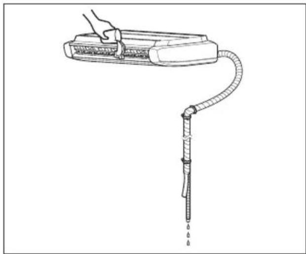
Drainage
- The drain pipe must be directed downwards.
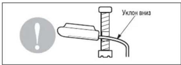
2. Do not install the water outlet in this way.

- When connecting several drain pipes together, follow the rules described below.
Drain pipes must have a downward slope (from 1/50 to 1/100): a change from a downward to an upward slope is not allowed, to avoid backflow.

Connect the wire to the control panel terminals according to the wiring diagram for the external unit.
The terminal numbers, wire colors of the external unit and the internal units must match.

WARNING
Check that the screws in the terminals are tightened well.

CAUTION
Check that all the above conditions are met, and prepare for wiring. 1) Do not use any other electrical equipment, except that specifically intended for the compressor.
For wiring, follow the wiring diagram shown on the inside of the switch box cover.
2) Install an automatic electrical switch between the power source and the unit. 3) The screws used to secure the electrical equipment wires may loosen due to vibration during transport of the unit.
Check them and make sure they are tightened.
(Weak tightening can cause a fire in the electrical wiring.)
4) Connect the power supply cable. 5) Check that the power supply is sufficient. 6) Make sure that the starting voltage is not less than 90% of the rated voltage indicated on the nameplate with factory characteristics. 7) Make sure that the cable thickness matches the thickness specified in the power supply specifications. (In particular, pay attention to the ratio of length and thickness of the cable.) 8) Do not forget to take care of protection if operation is carried out in a humid environment. 9) Voltage drop can be caused by the following reasons.
Electromagnetic interference, damage to the contact zone, melting of the wire, failure of the overload protection unit. The compressor may not have sufficient starting power.
FRAME
Explain to the buyer the basic operating and maintenance procedures, using this operating manual (cleaning the air filter, adjusting the temperature, etc.).
INSTALLATION OF THE WIRED REMOTE CONTROL
If the temperature sensor is located on the remote control, then to ensure accurate temperature measurement, it must be installed in a place protected from direct sunlight, high humidity, and direct flow of cold air. Install the remote control at a distance of 1.5 m from the floor in an area where the average temperature is maintained and good air circulation exists.
Do not install the remote control where it will be affected by the following factors.
- Drafts from doors or windows. - Hot or cold air flows from the duct. - Heat sources (from the sun or heating devices). - Hidden pipes and chimneys. - Uncontrolled areas (above walls or behind the remote control). - The remote control equipment is 7-segment XXN-display.
For information to be displayed correctly, the remote control must be installed as shown in Fig.1 (standard height - 1.2~1.5 m from the floor level).
Fig.1. Typical location of the remote control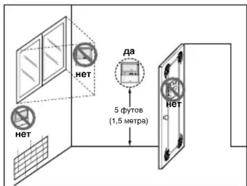
Assembly of the side cover
- Close the main body with the side covers, as shown in the figure.
- Slightly lift the corner of the cover with your hands to fix it on the panel.
- Press the side cover from the front (from the side of the discharge opening) towards the air intake grille to fix it inside the main body. 4. Tighten the mounting screws.
Installation of the wired remote control
1. Secure the wired remote control panel in the chosen location.
- Make sure the panel is not bent, otherwise the remote control will operate with errors.
Install the remote control panel in the supplied housing, if it is included in the delivery set.
2. The cable of the wired remote control can be installed in three directions.
- Installation directions: on the housing surface, upward, to the right
- When laying the remote control cable along the top and right side, first remove the guide.
Remove the guide.
① Housing surface ② Upper guide ③ Right guide
3. Secure the upper part of the remote control to the panel installed on the wall surface, as shown in the figure, then press the lower part of the remote control to the panel.
Make sure there are no gaps between the panel and the remote control.
Remove the remote control from the panel as shown in the following figure. Insert a screwdriver into the lower removal hole, turn it clockwise, and remove the remote control.
- The remote control has two removal holes in total. Use them alternately. When removing the remote control, be careful and try not to damage the internal components.
- Connect the internal unit and the remote control using the connection cable.
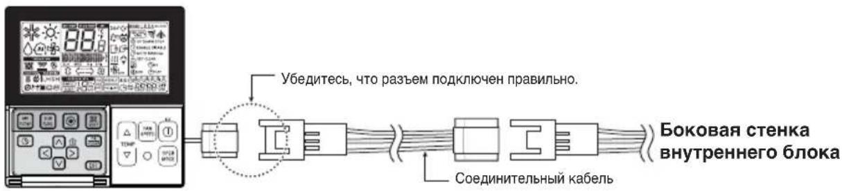
- If the distance between the wired remote control and the internal unit exceeds 10 m, use an extension cable.
CAUTION
Do not install the remote control panel into a wall.
(This may lead to damage of the temperature sensor.)
Do not install cables longer than 50 m.
(This may lead to incorrect operation of the controller.)
- When installing the remote control panel, check the direction of the connector on the side of the remote control panel and the side of the device to which the connection is made.
- If you install the remote control cable in the opposite direction, the connector will not connect.
- Technical characteristics of cable 2547 1007 22# 2-core, 3-core, 5-core or more in the option.
Name and function of the remote control panel (optional)
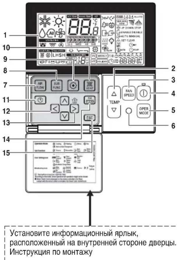
1. Display 2. Temperature adjustment button 3. Fan speed selection button
- Fan speed is adjusted by the buttons.
- ON/OFF button
- Mode selection button
6. Remote control panel - some devices do not accept wireless signals. 7. Airflow button 8. Function button 9. Function selection button 10. Ventilation button
- It does not work
- Reservation
- Press the button up, down, left, right
- For indoor temperature, press the button
- Temperature display button in the room
It only shows the room temperature in the display unit. - In this case, the room temperature is not controlled. In case of air intake, it displays the temperature around the unit. temperature around remote controller.
- Set/Cancel button
- Exit button
- Some functions may not work or display depending on the model. *If the remote controller is not connected, an unclear value will be displayed.
Model: PQRCVSL0 (Black color)
PQRCVSLOQW (White color)
Adjustment of the two-position switch on the printed circuit board of the internal unit
Two-position switch on the printed circuit board (internal units of cassette and duct type)
① Setting the master
- No. 3 OFF - No. 3 ON
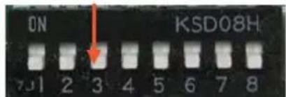
② Setting the slave
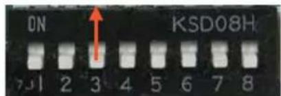
- You can control up to 16 internal units (max.) from one wired remote controller RC. Set only one internal unit to master mode, and set the others to slave mode.
- You can connect internal units of any type.
- You can also use the wireless remote controller simultaneously.
- You can also connect a dry contact central control remote controller simultaneously.
- The master internal unit can recognize only dry contact and central control remote controllers. - In case of simultaneous operation of central and group remote controllers, you can connect standard internal units of series 2 and later with software from 2009. - In case of setting the central remote controller, you can control the internal units with the central remote controller after setting the address of the master internal unit.
- The slave internal unit will operate as the master internal unit.
- The slave internal unit cannot be controlled only from the central remote controller. - Some remote controllers RC do not work simultaneously with dry contact and central remote controller. For additional information on this issue, please contact us.
- If an error occurs in the internal unit, the wired remote controller Dv will display it.
Errors in the internal unit can be cleared by operating the internal unit separately.
- In the case of group control, the following functions can be used.
- Selecting the operation mode (operation/stop/mode/temperature setting)
- Airflow speed control (high/medium/low) - some functions are not available.
The leading and following internal units can be set using the buttons on the wired remote controller. The internal units can be connected to the remote controller up to 2009.
In some cases, contact LGE.
*During the setting of the leading and following units, malfunctions may occur.
Standard: Standard internal unit
4.2 Remote controller Dv
Wired remote controller Dv 2 + Internal unit 1
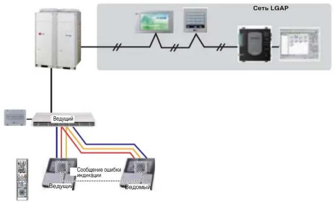
- Two wired remote controllers Dc can be connected to one internal unit. 2. Depending on the type of internal unit, two remote controllers DY can be connected.
- Currently, a wireless remote control DY can be used.
- It is possible to connect both a dry contact and a spiral remote control simultaneously.
- Any error in the internal unit is displayed on the wired remote control DY.
- There are no limits for the functionality of internal units. *No more than 2 wired remote controls DY can be connected to 1 internal unit.
5. Auxiliary equipment for setting up group control
Group control can be set up using the auxiliary equipment mentioned above.




- TABLE OF CONTENTS
- INSTALLATION REQUIREMENTS
- REQUIRED PARTS REQUIRED TOOLS
- INSTALLATION
- INTRODUCTION
- SYMBOLS USED IN THIS MANUAL
- FEATURES
- SAFETY PRECAUTIONS
- WARNING
- CAUTION
- OPERATION
- SELECT THE BEST LOCATION
- INDOOR UNIT
- PREPARING WORK FOR INSTALLATION
- OPEN SIDE COVER
- MOUNTING THE ANCHOR NUT AND BOLT
- DRILL A HOLE IN THE WALL
- INDOOR UNIT INSTALLATION
- INSTALLATION INFORMATION FOR DECLINATION
- FRONT VIEW
- SIDE VIEW
- PREPARATION OF PIPING
- CUT THE PIPES AND THE CABLE
- BURR REMOVAL
- FLARING WORK
- CHECK
- FLARE SHAPE AND FLARE NUT TIGHTENING TORQUE
- PRECAUTIONS WHEN CONNECTING PIPES
- OPENING SHUTOFF VALVE
- CLOSING SHUTOFF VALVE
- TIGHTENING TORQUE
- HEAT INSULATION
- CHECKING THE DRAINAGE
- TO CHECK THE DRAINAGE
- DRAIN PIPING
- WIRING CONNECTION
- HANDOVER
- WIRED REMOTE CONTROLLER INSTALLATION
- DO NOT INSTALL THE REMOTE CONTROLLER WHERE IT CAN BE AFFECTED BY
- SIDE COVER ASSEMBLY
- INSTALLATION OF WIRED REMOTE CONTROLLER
- NAME AND FUNCTION OF WIRED REMOTE CONTROLLER (ACCESSORY)
- GROUP CONTROL SETTING
- GROUP CONTROL
- N DIP SWITCH IN PCB
- REMOTE CONTROL
- ACCESSORIES FOR GROUP CONTROL SETTING
- INSTALLATION MANUAL
- AIR CONDITIONER
- REQUIRED ACCESSORIES
- REQUIRED TOOLS
- FUNCTIONAL NODES
- FIRMLY SECURE THE COVER OF THE SWITCH BLOCK
- ALWAYS INSTALL THE SPECIFIED FUSE IN THE AUTOMATIC CIRCUIT BREAKER
- USE AN AUTOMATIC CIRCUIT BREAKER OR FUSE OF THE CORRECT RATING
- DO NOT MODIFY OR EXTEND THE POWER CORD
- DO NOT TURN ON THE AIR CONDITIONER IF THE DOOR OR WINDOW IS OPEN OR IF THE HUMIDITY IS VERY HIGH
- BE CAREFUL WHEN UNPACKING AND INSTALLING THE PRODUCT
- SELECTION OF INSTALLATION LOCATION
- PREPARATORY WORK BEFORE INSTALLATION
- OPEN THE SIDE PANEL
- INSTALLATION OF THE ANCHOR BOLT AND TANK
- MAKE A HOLE IN THE WALL
- INSTALLATION OF THE INDOOR UNIT
- WHEN INSTALLING WITH A SLOPE
- DRAIN HOSE
- PREPARATION OF THE PIPE ROUTING
- CUT THE PIPE AND CABLE
- REMOVE BURRS
- FLARING
- CONE SHAPE AND TIGHTENING TORQUE OF CONE NUT
- PRECAUTIONS FOR CONNECTING PIPES
- SHUT-OFF VALVE
- THERMAL INSULATION
- DRAINAGE CHECK
- DRAINAGE
- FRAME
- INSTALLATION OF THE WIRED REMOTE CONTROL
- DO NOT INSTALL THE REMOTE CONTROL WHERE IT WILL BE AFFECTED BY THE FOLLOWING FACTORS
- ASSEMBLY OF THE SIDE COVER
- SECURE THE WIRED REMOTE CONTROL PANEL IN THE CHOSEN LOCATION
- THE CABLE OF THE WIRED REMOTE CONTROL CAN BE INSTALLED IN THREE DIRECTIONS
- SECURE THE UPPER PART OF THE REMOTE CONTROL TO THE PANEL INSTALLED ON THE WALL SURFACE, AS SHOWN IN THE FIGURE, THEN PRESS THE LOWER PART OF THE REMOTE CONTROL TO THE PANEL
- REMOVE THE REMOTE CONTROL FROM THE PANEL AS SHOWN IN THE FOLLOWING FIGURE. INSERT A SCREWDRIVER INTO THE LOWER REMOVAL HOLE, TURN IT CLOCKWISE, AND REMOVE THE REMOTE CONTROL
- NAME AND FUNCTION OF THE REMOTE CONTROL PANEL (OPTIONAL)
- REMOTE CONTROLLER DV
- AUXILIARY EQUIPMENT FOR SETTING UP GROUP CONTROL
Brand : LG
Model : MULTI V URNU48GVLA2
Category : Water pump