
HGPM12EOG8 - Industrial gripper Festo - Free user manual and instructions
Find the device manual for free HGPM12EOG8 Festo in PDF.
| Product type | Micro parallel gripper |
| Brand | Festo |
| Model | HGPM12EOG8 |
| Main function | Grasp and hold payloads in handling |
| Gripping direction | From the outside (EO) |
| Power supply | Compressed air |
| Maximum operating pressure | 8 bar |
| Jaw thread | M3 |
| Maximum screw-in depth | 4 mm |
| Max. tightening torque (temporary) | 0,8 Nm |
| Actuation type | Single-acting with spring return |
| Maintenance and cleaning | Soft cloth and soapy water (max 60 °C) |
| Repair | Send to Festo |
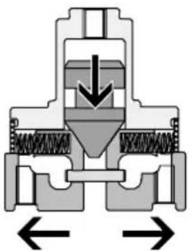
| Safety | Use a pressure build-up valve (type HEL-...) |
| Compliance | Observe load limits and operating instructions |
Frequently Asked Questions - HGPM12EOG8 Festo
User questions about HGPM12EOG8 Festo
0 question about this device. Answer the ones you know or ask your own.
Ask a new question about this device
Download the instructions for your Industrial gripper in PDF format for free! Find your manual HGPM12EOG8 - Festo and take your electronic device back in hand. On this page are published all the documents necessary for the use of your device. HGPM12EOG8 by Festo.
USER MANUAL HGPM12EOG8 Festo
Micro-Parallelgreifer Microparallelgripper
HGPM-...-G..
natural_image
Close-up of a mechanical component with mounting holes and a reflective surface (no visible text or symbols)FESTO
Fitting and commissioning tobecarried out by qualified personnel only in accordance with the operating instructions.
text_image
Technical diagram of a mechanical valve or actuator with labeled parts and directional arrows indicating flow or movement.natural_image
Three simple scientific icons: thermometer, droplet pattern, and analog clock (no text or symbols)Bild5

natural_image
Exploded view diagram of a mechanical component with bolts and housing (no text or labels)Bild7
natural_image
Mechanical assembly diagram showing two configurations with directional arrows and a cross symbol (no text or labels)Bild9
natural_image
Pure mechanical diagram showing intersecting gears and blocks without any text or symbolsBild12
natural_image
Pure electrical circuit lines without any symbolsBild13
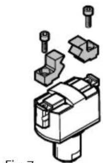
8 Z u b e h ö r
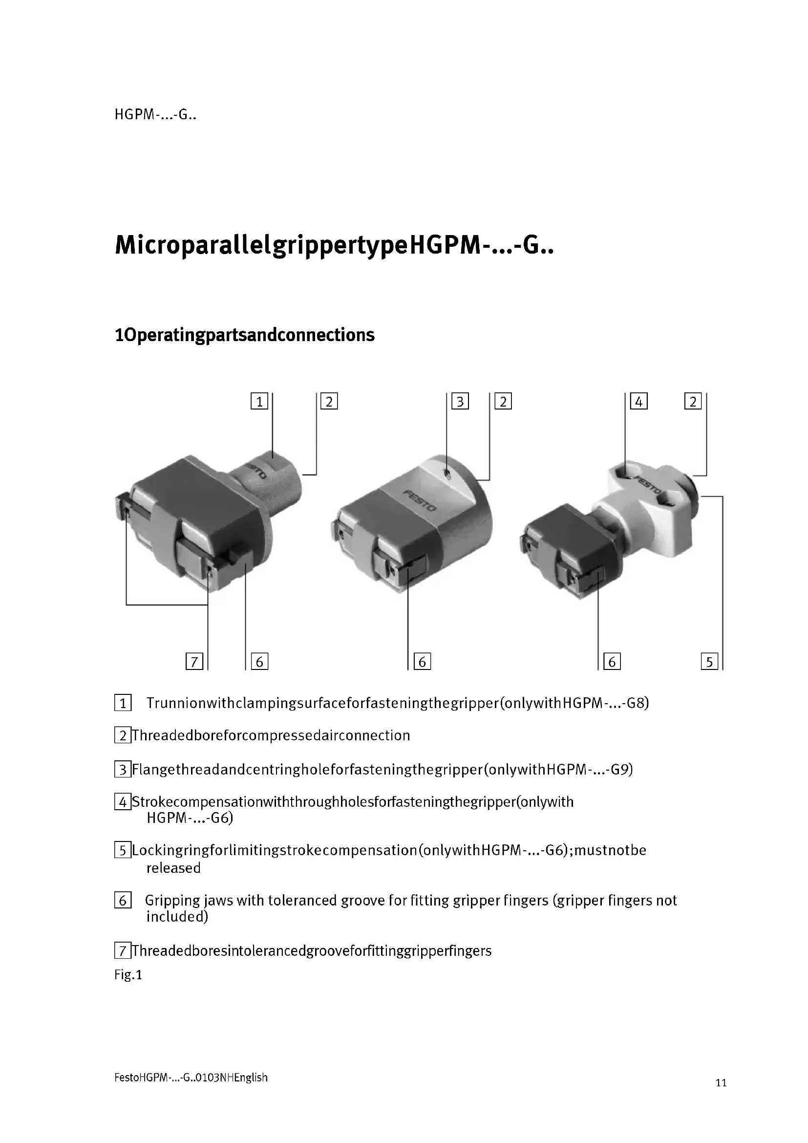
1 Trunnionwithclampingsurfaceforfasteningthegripper(onlywithHGPM-...-G8)
2 Threadedboreforcompressedairconnection
3 Flangethreadandcentringholeforfasteningthegripper(onlywithHGPM-...-G9)
4 Strokecompensationwiththroughholesforfasteningthegripper(onlywith HGPM-...-G6)
5 Lockingringforlimitingstrokecompensation(onlywithHGPM-...-G6);mustnotbe released
6 Gripping jaws with tolerated groove for fitting gripper fingers (gripper fingers not included)
7 Threadedboresintolerancedgrooveforfittinggripperfingers
Fig.1
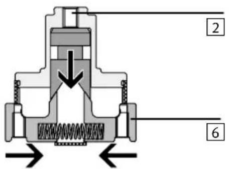
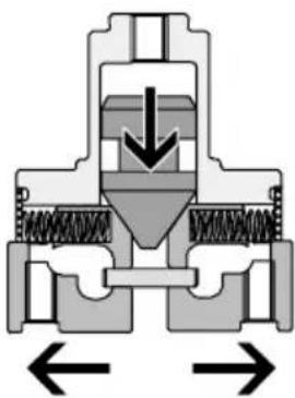
2Functionandapplication
Whencompressedairisappliedtoconnection 2, the pistonofthemicroparallelgripper HGPM-...ispressedagainstamechanism.
Amechanismtransfersthelongitudinalmove- mentofthepistontothegripperjaws ^6 . Gripperfingersarefastenedtothegripper jaws.Whenthejawsopen,theycangripwork loadsbytheinnercontour;whenthejaws close,theycangripworkloadsbytheouter contour.
The microparallelgripperHGPM-...issingle-actinganddependingonthemechanismit can be used for gripping from the outside or from the inside.
Whenthegripperisexhausted, aresetspring returnsthegripperjawstothestartingposition:
-gripperfingersopen:onHGPM-...-EO-...
-gripperfingersclosed:onHGPM-...-EZ-...
The HGPM-...is designed forgripping and holding workloads in handling processes.
text_image
Technical diagram of a mechanical valve or actuator with labeled parts and directional arrows indicating flow or movement.Fig.2

natural_image
Cross-sectional diagram of a mechanical valve or pump assembly with directional arrows indicating flow or movement (no text or labels)Fig.3
3Conditionsofuse

Pleasenote
Incorrecthandlingcanleadtomalfunctioning.
- Observethefollowinginstructionsinordertoensurecorrectandsafeuseof theproduct.
- Comparethevaluesspecifiede.g.forpressures,forces,torquesandtemperatureswithyouractualapplication.
- Makesurethatthereisasupplyof correctlypreparedcompressedair.
- Please observe also therelevant technical regulations, as well as national and local regulations.
- Remove all transport materials such as protectivewax, foils, caps and cartons. Thewastematerials can be disposed of in separate containers for recycling.
•Takeintoacccounttheprevailingambient conditions.
LF-...LR-...
flowchart
graph TD
    A["Decision"] --> B["Process Box"]
    B --> C["Output"]
Fig.4
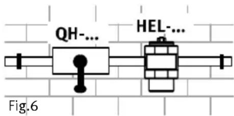
- Pressurizeyourcompletesystemslowly (e.g.withasafetysart-upvalvetype HEL-...).
- Observethewarningsandinstructions ontheproductandintheseoperating instructions.
- Use the product in its original condition without undertaking any modifications.
[°C]
[%]
[mbar]

Fig.5
text_image
QH-... HEL-... Fig.64Fitting
Mechanicalcomponents
Fasteningthegripperfingers
- Usegrippingfingersasshortandaslight aspossible.
- Screwtwofasteningscrewsintothe threadedholesineachofthegripping jaws.
Themaximumscrewdepthmustnotbe exceeded. Otherwisethefunctioncanbe affected.
natural_image
Exploded view diagram of a mechanical component with bolts and housing (no text or labels)Fig.7
The different gripping jawshavethe following connection threads:
| HGPM-08HGPM-12 | ||
| Jawwidth(toleranced)3 | +0,05 mm | 4+0,05mm |
| ThreadsizeM2.5M3 | ||
| Max.permittedscrewdepth(onlywithHGPM-...-EO...)4 m m 4 m m | ||
| Max.tighteningtorque(short-term) | 0.4Nm | 0.8Nm |
Fig.8
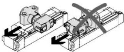
FittingtheHGPM-...

Pleasenote
Highaccelerationforcesinthelongitudinal directionofthegripper(e.g.whenfittedon moving parts such as the DGP-...) reduce thegrippingforce.
- Makesurethattheresultingworkload forcesliewithinthereducedgripping forcerange.
natural_image
Mechanical assembly diagram showing two configurations with directional arrows and a cross symbol (no text or labels)Fig.9
- Fasten the HGPM-... depending on the rated size according to the table below.
| Type | HGPM-... | |||||
| 08-...12-... | 08-...12-... | 08-...12-... | ||||
| G8G6G9 | ||||||
| Fasteningtype | ontheclamping surface of the trunnion 1  | bymeansofthe throughholesinthe strokecompensation*) 4 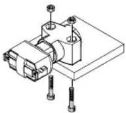 | withthefastening nutssupplied 3 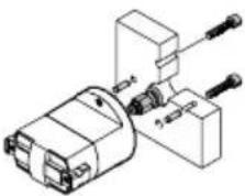 | |||
| ThreadM3M3M3 | M4M3M3 | |||||
| Max.tightening torque | 1.2Nm1.2 | Nm1.2Nm2, | 9Nm1.2Nm | 1.2Nm | ||
| *)Fastenwithadhesive | ||||||
Fig.10
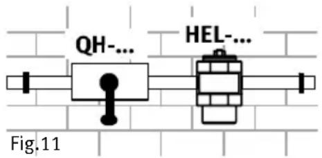
5Commissioning
Completesystem
- Slowlypressurizeyourcompletesystem.
This will prevent any uncontrolled movements.
Thesafetystart-upvalvetypeHEL-...or HEM-...canbeusedforslowpressurizationduringthestartingphase.
text_image
QH-... HEL-... Fig.11Individualunit
- Observethepermittedvaluesforthefollowing(seecatalogue):
-themaximumgripperforceasafactoroftheleverarmandtheeccentricity
-themaximumpermittedgrippingtimes
-themaximumgripperfingerweightforce.

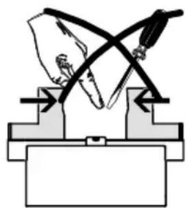
Warning
Movingpartscancauseinjurytohands andfingers.
•Thereforemakesurethat:
—nobodycanplacehis/herhand
betweenthegripperfingers
-noobjectsliewithintherangeofthe
gripperfingers.
natural_image
Pure mechanical diagram showing a lever mechanism with no text or symbolsFig.12
- Startatestrun
-atfirstwithslowpositioningmovements
-thenunderapplicationconditions.
TheHGPM-...mustholdtheworkloadsecurely.
•Concludethetestrun.
Thegrippershouldnowbeexhausted.
HGPM-...-G..
6Careandmaintenance
- If necessary, clean the exterior of the HGPM -... with as soft cloth. The permitted cleaning medium is soapsuds, max. +60°C.
7Dismantlingandrepairs

Warning
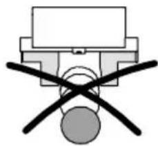
If there is adropin pressure, the work load wills suddenly slidedown.
- Makesurethatthegripperisnot holdingaworkloadwhenitis exhausted.
natural_image
Pure electrical circuit lines without any symbolsFig.13
8Accessories
| DesignationType | |
| SafetyvalveHEL-.../HEM-... | |
| AdapterplateAM-.../HAPG-... |
Fig.14
9Eliminatingfaults
| FaultPossiblecause | Remedy | |
| Grippercannot holdmass | MasstoolargeSelectsmallermass | |
| Grippingonlywithforceof resetspringinwronggripping direction | Useintendeddirectionof gripping | |
| PressuretoolowIncreasepressure | to max.8bar | |
| Holdingpointofgripperstoo faroutsideturningpoint(see section“Characteristiccurves”) | Moveholdingpointindirection ofturningpoint | |
| Gripperdoesnot open/close | CompressedairnotappliedCheck | compressedair connection |
| GripperdefectiveReturngripperto | Festo |
Fig.15
HGPM-...-G..
MicropinzaparalelatipoHGPM-...-G..
text_image
Technical diagram of a mechanical valve or actuator with labeled parts and directional arrows indicating flow or movement.Fig.2
natural_image
Cross-sectional diagram of a mechanical valve or pump assembly with directional arrows indicating flow or movement (no text or labels)Fig.3
3Condicionesdeuso

Porfavor, observar
natural_image
Exploded view diagram of a mechanical component with bolts and housing (no text or labels)Fig.7
natural_image
Mechanical assembly diagram showing two configurations with directional arrows and a cross symbol (no text or labels)Fig.9
natural_image
Pure mechanical diagram showing intersecting blades and supports without any text or symbolsFig.12
natural_image
Cross-sectional diagram of a mechanical valve or pump assembly with directional arrows indicating flow or movement (no text or labels)natural_image
Three black-and-white icons: thermometer, droplet symbols, and analog clock (no text or labels)Fig.5

natural_image
Exploded view diagram of a mechanical component with bolts and housing (no text or labels)Fig.7
natural_image
Mechanical assembly diagram showing two configurations with directional arrows indicating motion (no text or labels)Fig.9
natural_image
Pure mechanical diagram showing a lever mechanism with no text or symbolsFig.12
natural_image
Pure electrical circuit lines without any symbolsFig.13
8Accessoires
text_image
Technical diagram of a mechanical valve or pump assembly with labeled parts and directional arrows indicating flow or movement.Fig.2HGPM-...-EO-...
natural_image
Cross-sectional diagram of a mechanical valve or pump assembly with directional arrows indicating flow or movement (no text or labels)text_image
Electrical circuit diagram with diode, resistor, and dashed line indicating a fault or measurement setupFig.4
[°C][%][mbar]
natural_image
Three black-and-white icons: thermometer, droplet drop, and analog clock (no text or symbols)Fig.5

- Alimentaregradualmentel'impianto.UtilizzareatalscopolavalvoladiinserimentotipoHEL-....
natural_image
Exploded view diagram of a mechanical component with exploded view (no text or labels)Fig.7
Peridiversitipidiutensilidipresasonoprevistelefilettaturediraccordoindicate nellaseguentetabella:
natural_image
Mechanical assembly diagram showing two configurations with directional arrows and a cross symbol (no text or labels)Fig.9
natural_image
Pure mechanical diagram showing a lever mechanism with no text or symbolsFig.12
natural_image
Pure electrical circuit lines without any symbolsFig.13
8Accessori
| DenominazioneTipo | |
| ValvoladiinserimentoHEL-.../HEM-... | |
| PiastradiadattamentoAM-.../HAPG-... |
Fig.14
natural_image
Cross-sectional diagram of a mechanical valve or actuator component with no visible text or symbolsnatural_image
Three black-and-white icons: thermometer, droplet drop, and analog clock (no text or symbols)Bild5

natural_image
Exploded view diagram of a mechanical component with bolts and housing (no text or labels)Bild7
natural_image
Mechanical assembly diagram showing two configurations with directional arrows and a cross symbol (no text or labels)Bild9
natural_image
Pure mechanical diagram showing intersecting gears and blocks without any text or symbolsBild12
natural_image
Pure electrical circuit lines without any symbolsBild13
8Tillbehör
Thereproduction, distribution and utilization of this document as well as the communication of its content to others without express authorization is prohibited. Offenders will be held liable for the payment of damages. All rights reserved in the event of the grant of a patent, utility module or design.