PROX240S - Speaker FoneStar - Free user manual and instructions
Find the device manual for free PROX240S FoneStar in PDF.

| Product type | Sound reinforcement amplifier (PA) |
| Brand | FoneStar |
| Model | PROX240S |
| Output power | 240 W RMS |
| Frequency response | 40 Hz – 20 kHz (-10 dB) |
| Distortion (THD+N) | < 1% at 1 kHz |
| Signal-to-noise ratio | > 77 dB |
| Speaker output impedance | 4 Ω (low impedance) or 100 V line (42 Ω) |
| Microphone/line inputs | 4 channels (CH1 with priority, CH2-CH4) with MIC/LINE/Phantom +48 V selection |
| Auxiliary inputs | 2 (AUX1, AUX2) on RCA or Euroblock |
| Emergency input | 1 100 V line input on Euroblock |
| Remote mute input | 1 REMOTE MUTE input on Euroblock (contact closure) |
| Line output | 1 stereo output on RCA (level 1.25 V RMS) |
| Speaker output | Screw terminals: 4 Ω + COM or 100 V + COM |
| Controls | Per-channel volume, Master, AUX input selector, tone (Bass/Treble ±10 dB), mic gain, VOX sensitivity |
| Indicators | Power (POWER), Signal, Clip, Protection (PROT) |
| Protections | Overload, short circuit, thermal protection (forced ventilation) |
| Power supply | 230/115 V AC 50-60 Hz, 480 W (fuse 4 A/230 V or 8 A/115 V) |
| Dimensions (W x H x D) | 433 x 89 x 360 mm (2U rack 19") |
| Included accessories | Power cable, rack mounting brackets |
| Maintenance and cleaning | Disconnect before cleaning. Use a dry, soft cloth. Do not use solvents. |
| Safety | Do not block ventilation slots. Check speaker compatibility (impedance and power). |
Frequently Asked Questions - PROX240S FoneStar
User questions about PROX240S FoneStar
0 question about this device. Answer the ones you know or ask your own.
Ask a new question about this device
Download the instructions for your Speaker in PDF format for free! Find your manual PROX240S - FoneStar and take your electronic device back in hand. On this page are published all the documents necessary for the use of your device. PROX240S by FoneStar.
USER MANUAL PROX240S FoneStar
INSTRUCTION MANUAL/MANUAL DE USUARIO/
MODE D'EMPLOI/MANUAL DE INSTRUÇÕES
DESCRIPTION
- Distributed audio for PA installations with 100 speakers, also with low impedance output.
- Safe and durable connections with low maintenance.
- With 3 mic/line inputs and 2 auxiliary inputs.
- User-friendly operation and a modern, discreet design.
CONTROLS AND FUNCTIONS
FRONT PANEL
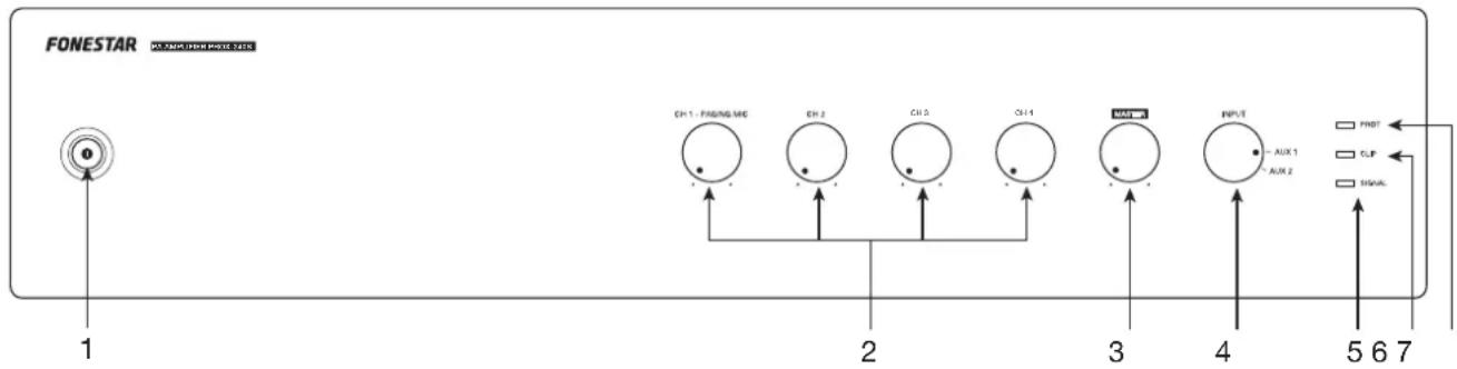
1.- :Indicator light and on/off switch of the amplifier.
2.- CH 1 - PAGING MIC/CH 2/CH 3/CH 4: volume controls for the CH 1, CH 2, CH 3 and CH 4 inputs on the rear panel.
3.- MASTER: volume control of the input selected by the INPUT selector switch.
4.- INPUT: input source selector: AUX 1 o AUX 2.
5.- SIGNAL: output signal status LED indicator. Lights up when signal is detected at the outputs.
6.- CLIP: output signal peak LED indicator. If it is turned on, you must reduce the volume of the input that produces it and/or the output. Do not allow this indicator light to remain on continuously.
7.- PROT: protection LED indicator. Lights up when the amplifier protection is activated to prevent component damage. With protection enabled, the audio output of that channel is cut off. If this happens, turn off the device, make sure that the air intake and exhaust slots are clear of obstructions, turn down the volume of the input signal and check that the speakers connected to the output are working properly and are suitable for this output (power and impedance). Wait a few minutes for the appliance to stabilize before you switch it on again.
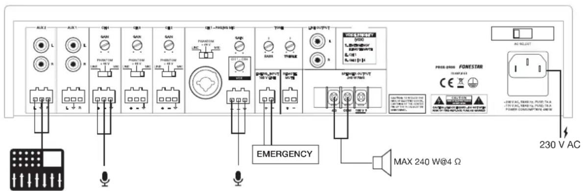
REAR PANEL

1.- AUX 2/AUX 3: stereo auxiliary inputs for connection of audio devices such as mixers, computers, etc. These inputs have 2 connector options, 2 x RCA or euroblock.
2.- CH 2/CH 3/CH 4: audio inputs from dynamic microphone (MIC), condenser microphone (PHANTOM +48 V) or lines (LINE), balanced eurolock connector. Once the input type has been selected with the MIC/PHANTOM +48 V/LINE selector, the gain of the input can be adjusted with the GAIN control.
3.- CH 1 - PAGING MIC: priority audio input for dynamic microphone (MIC), condenser microphone (PHANTOM +48 V) or lines (LINE), balanced combo connectors (XLR and 6.3 mm jack) and eurolock. Once the input type has been selected with the MIC/PHANTOM +48 V/LINE selector, the gain of the input can be adjusted with the GAIN control.
4.- VOX CH 1 - CH 4: setting the sensitivity to make the CH 1-4 inputs priority over all other signals. Depending on this setting, the signal level required at the CH 1-4 inputs to cut audio from other sources will be higher or lower. If the VOX control is set to minimum, no audio will be cut off from any output when there is signal on CH 1-4. Please note the order of priority of the amplifier inputs, for more information see section CONNECTION - PRIORITY OF INPUTS.
5.- EMERG. INPUT (100 V LINE): 100 V audio input for connecting an emergency system, euroblock.
6.- BASS: boosts/attenuates low frequencies.
7.- TREBLE: boosts or attenuates high frequencies.
8.- REMOTE MUTE: mute/unmute the speaker output remotely with the help of a switch, euroblock connector. This input is in open circuit, to silence it you must close the circuit.
9.- LINE OUTPUT: line output, 2 x RCA connectors. The output level is affected by the volume of the inputs and the MASTER.
10.- SPEAKER OUTPUT 240 W RMS: 4 Ω low impedance speaker output and 240 W RMS 100 V line, threaded connectors. Please note that the choice of low impedance speakers must conform to the amplifier specifications for serial or parallel connection (only parallel for 100 V line) to obtain power and impedance appropriate to the amplifier output.
11.- 115/230 V amplifier power supply input.
12.- AC SELECT: power supply voltage selector. If you need to change the voltage you should be aware that the fuse must be modified as specified on the product.
BASIC OPERATION
Select the operating mode using the INPUT control on the amplifier front panel.
AUX 1/AUX 2 INPUTS
- Select the desired mode by having the signal connected to the corresponding connector input on the rear panel of the amplifier.
- Activate the audio device (player, mixer, PC, smartphone, etc.) connected to the input to start playback.
NOTE: make sure that the signal from your audio device is loud enough to be heard through the amplifier. This allows you to control the volume from the amplifier itself at a later time without having to operate any other equipment.
CONNECTION
IMPORTANT: refrigerate the amplifier properly. To do this, make sure that the place where it is installed has access to airflow and that the slots in the chassis are free of obstructions.
- With the amplifier switched off, connect all audio sources AUX, CH, EMERG. INPUT.
- Connect the speakers to the corresponding low impedance output* (4 Ω + COM) or 100 V line* (100 V + COM) or to the stereo line output (LINE OUTPUT).
*IMPORTANT: for proper operation and performance of the equipment, use the correct power, impedance and frequency limits. Before connecting to other equipment, be aware of the conditions required in a HIGH IMPEDANCE (100 V) and LOW IMPEDANCE installation. More information can be found at
fonestar.com/downloads/install_fonestar_en.pdf
- Check that the volume and gain controls are at minimum, connect the amplifier to power.
- Turn on the amplifier and select input with the INPUT.
- Finally, adjust all volume, gain and equalization controls (BASS and TREBLE).
INPUT PRIORITY
- The EMERG input INPUT has the highest priority attenuating all other inputs when the input has a signal.
- CH 1 input has priority over inputs CH 2, CH 3, CH 4, AUX 1 and AUX 2. This priority is by signal level and can be selected with VOX control.
- And CH 2, CH 3 and CH 4 inputs has priority over input AUX 1, AUX 2 and its priority is set with the VOX control, just like as CH 1.
- The REMOTE MUTE input attenuates all inputs except the EMERG input. INPUT when a contact closure of its terminals is performed.
100 V LINE
![AUX 2 ALX 1 CM 4 CM 1 CM 2 CM 1 -PAMS/WEI VINCE LPG OUTPUT VOC REFINITY 5/000 1. 高通电源 接线器功能 8. CPT 8. GPT [1]c PROX-2008 FONESTAR AC SELECT EMERGENCY MAX 240 W@100 V -230 V AC POWER ON/OFFIC AC](/content/2026/03/523094/images/22059d19b3c7b2de4070b6f5bdb649a37e1764fb5ad1cb408f105ad35e3d987a.jpg)
LOW IMPEDANCE
BLOCK DIAGRAM
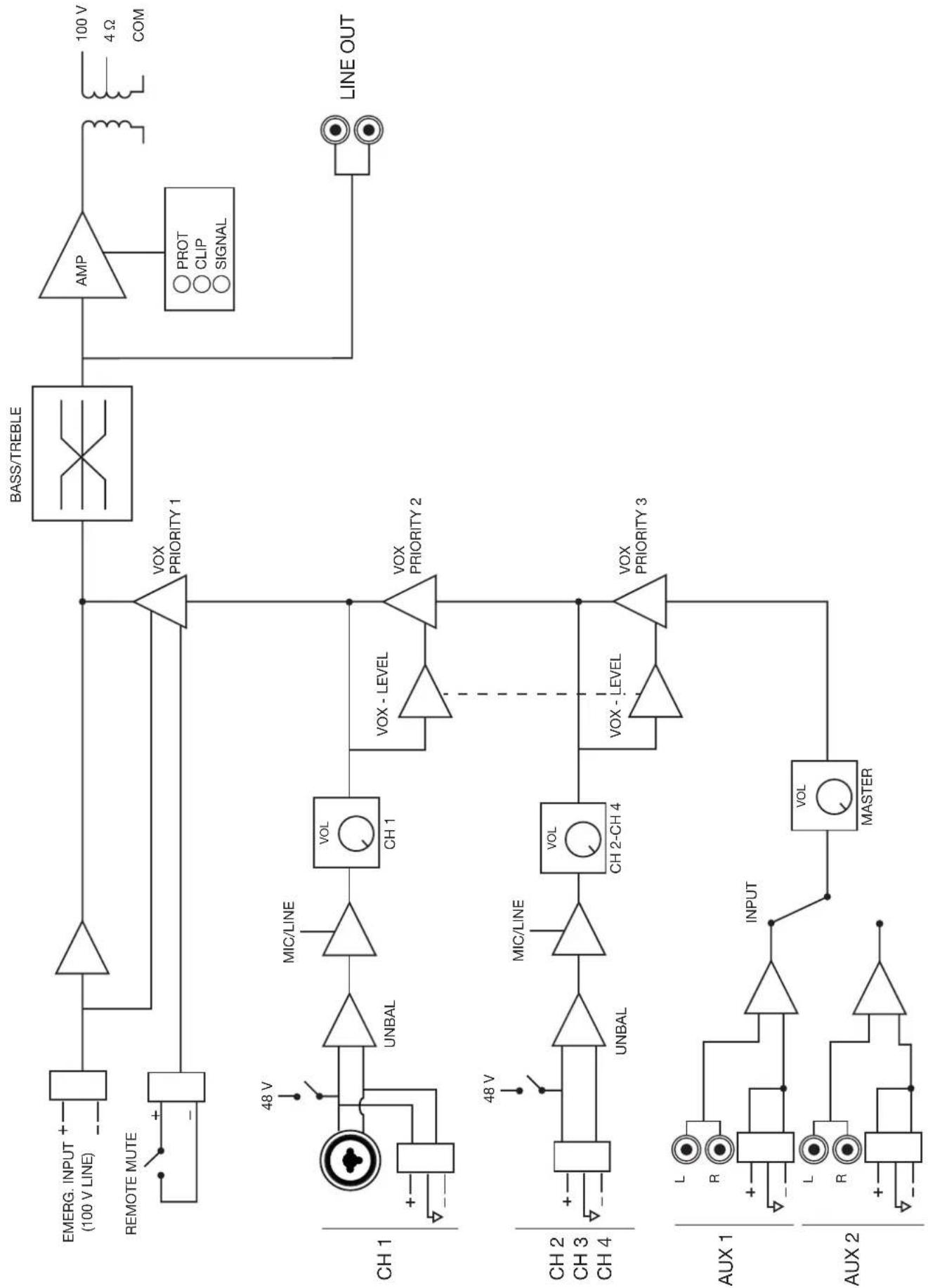
flowchart
graph TD
    subgraph_CH_1["CH 1"]
        EMERG_INPUT["EMERG. INPUT (100 V LINE)"]
        REMOTE_MUTE["REMOTE MUTE"]
        CH1 --> UNBAL["UNBAL"]
        UNBAL --> MIC/LINE["MIC/LINE"]
        MIC/LINE --> VOL_CH1["VOL CH 1"]
        VOL_CH1 --> VOX_PRIORITY1["VOX PRIORITY 1"]
        CH1 --> VOX_PRIORITY2["VOX PRIORITY 2"]
        CH1 --> VOX_PRIORITY3["VOX PRIORITY 3"]
        CH2 --> UNBAL
        CH2 --> MIC/LINE
        MIC/LINE --> VOL_CH2["CH 2-CH 4"]
        VOL_CH2 --> VOX_PRIORITY3
        CH3 --> UNBAL
        CH3 --> MIC/LINE
        MIC/LINE --> VOL_CH2
        VOL_CH2 --> VOX_PRIORITY3
        CH4 --> UNBAL
        CH4 --> MIC/LINE
        MIC/LINE --> VOL_CH2
        VOL_CH2 --> VOX_PRIORITY3
    end

    subgraph_CH_2["CH 2"]
        EMERG INPUT --> UNBAL
        CH2 --> UNBAL
        CH3 --> UNBAL
        CH4 --> UNBAL
        UNBAL --> MIC/LINE
        MIC/LINE --> VOL_CH2
        VOL_CH2 --> VOX_PRIORITY3
        CH2 --> UNBAL
        CH3 --> UNBAL
        CH4 --> UNBAL
    end

    subgraph_AUX_1["AUX 1"]
        EMERG INPUT --> R
        CH2 --> L
        CH3 --> R
        CH4 --> L
        CH2 --> INPUT
        CH3 --> R
        CH4 --> R
        R --> INPUT
        R --> VOLT["INPUT"]
        VOLT --> MASTER["MASTER"]
    end

    subgraph_AUX_2["AUX 2"]
        EMERG INPUT --> R
        CH2 --> L
        CH3 --> R
        CH4 --> L
        CH2 --> VOLT
        VOLT --> MASTER
    end

    subgraph BASS/TREBLE["BASS/TREBLE"]
        AMP["AMP"] --> OUT["100 V"]
        OUT --> COM["4 Ω"]
        OUT --> LineOUT["LINE OUT"]

    %% Legend: ○ PROT, ○ CLIP, ○ SIGNAL
    %% Note: The chart includes multiple nodes labeled with 'VIN' and 'V', but the structure of the diagram shows connections between lines, markers, and functional blocks.
| PROX-240S | |
| FEATURES PA Amplifier. Microphone inputs with mix, gain and priority level control. Tone controls. 100 V and 4 Ω outputs. | |
| POWER 240 W RMS | |
| RESPONSE 40-20,000 Hz (-10 dB) | |
| DISTORTION THD+N: <1% @ 1 kHz | |
| S/N RATIO >77 dB | |
| PROTECTIONS Overcurrent, DC and short-circuit at the output | |
| INPUTS CH 1 balanced mic/line with 48 V Phantom, Combo connector (XLR + 6.3 mm) and euroblock CH 2, 4 and 4 mic/line balanced with 48 V Phantom. Euroblock connector Mic signal level: 6 mV RMS (-44 dBV)/600 Ω Line signal level: 250 mV RMS (-12 dBV)/100 kΩ 2 AUX. 2 x RCA and euroblock connector. Signal level 300 mV RMS (-10 dBV)/47,000 Ω 1 emergency. Euroblock connector. Signal level loudspeaker line 100 V 1 Mute (Emergency Priority) by contact closure. Euroblock connector | |
| OUTPUTS 1 line. 2 x RCA connector. Signal level 1.25 V RMS (+2 dBV) 100 V or 4 Ω speaker output. Connector screw terminals | |
| IMPEDANCE | 4 Ω and 100 V (42 Ω) line |
| FUNCTIONS Input priority (voice over VOX inputs): 100 V Emergency input with highest priority, attenuates all other inputs Mute by contact closure, attenuates all inputs except the 100 V Emergency input Channel 1 with priority over all other inputs, level selectable Channel 2, 3 and 4 with priority over auxiliary inputs, level selectable Other functions: Power on, protection, signal peak and output signal indicator lights Temperature-controlled forced-ventilation cooling | |
| CONTROLS | Microphone volume Mic/line/phantom selector Master volume Aux input selector Tone: bass and treble (±10 dB 100 Hz and 10 kHz) Microphone gain Priority activation signal level (VOX) |
| TEMPERATURE Operation: 0° ~ 40°C | |
| MAXIMUM HUMIDITY | 95% |
| POWER SUPPLY 230/115 V AC 50-60 Hz, 480 W Fuse AC 230 V 4 A/115 V 8 A | |
| DIMENSIONS 433 x 89 x 360 mm depth. 2 U 19" rack | |
| ACCESSORIES Power cable Rack mounts | |