SONAIR-PRO-2P - Speaker FoneStar - Free user manual and instructions
Find the device manual for free SONAIR-PRO-2P FoneStar in PDF.


User questions about SONAIR-PRO-2P FoneStar
0 question about this device. Answer the ones you know or ask your own.
Ask a new question about this device
Download the instructions for your Speaker in PDF format for free! Find your manual SONAIR-PRO-2P - FoneStar and take your electronic device back in hand. On this page are published all the documents necessary for the use of your device. SONAIR-PRO-2P by FoneStar.
USER MANUAL SONAIR-PRO-2P FoneStar
SONAIR-PRO-2P, SONAIR-PRO-2M, SONAIR-PRO-2MP
natural_image
Three black wireless audio devices: a two-wire network, a two-wire microphone, and a front-end earless device (no visible text or symbols)INSTRUCTION MANUAL/MANUAL DE USUARIO/MODE D'EMPLOI/MANUAL DE INSTRUÇÕES
FONESTAR
DESCRIPTION
- Wireless microphone with superior sound, stable operation and excellent interference behaviour.
- The microphone integrates the ID Pilot function which pairs the receiver and transmitter with a unique 16-bit code, preventing other microphones from interfering even on the same frequency. In addition, the diversity reception with two antennas ensures the best RF reception.
- The display on the microphone and on the receiver easily informs about frequency and battery status. Facilitating the control of microphones.
- The transmitter uses an integrated audio and transmission management solution on a single chip, with frequency selection and efficient power management to maximise battery life. FM modulation technology with high sound quality.
- The receiver and microphone channels are quickly synchronised with the IR synchronisation function.
- UHF frequency range with selectable transmission channels.
- Receiver with colour display and low noise balanced and unbalanced output for easy connection.
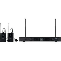
- SONAIR-PRO-2P: dual receiver + 2 belt-pack with clip-on microphone.
SONAIR-PRO-2M: dual receiver + 2 hand-held microphone.
SONAIR-PRO-2MP: dual receiver + 1 hand-held + 1 belt-pack with clip-on microphone.
CONTROLS AND FUNCTIONS
SONAIR-PRO-2P, SONAIR-PRO-2M & SONAIR-PRO-2MP RECEIVER
text_image
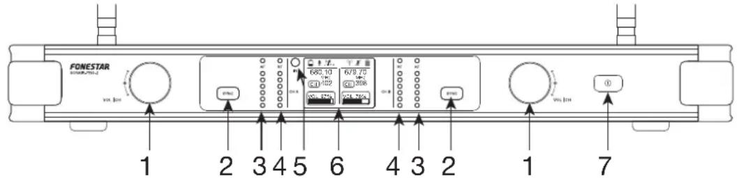
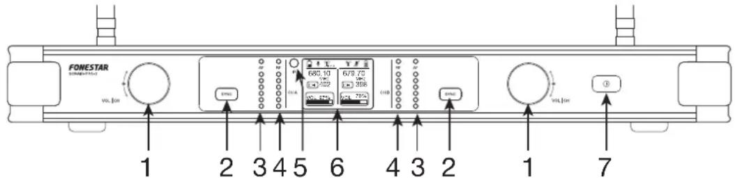
FONESTAR 680 10 679 75 64 102 63 306 63 304 1 2 3 4 5 6 4 3 2 1 71.- VOL | CH: multifunction controls.
- rotation: independent volume controls for channels A and B on the audio outputs.
- long press + rotate: enters the configuration mode and selects the channel (transmission frequency), the channel number will be shaded when this mode is active CH 402 → CH 402. To exit the configuration mode, long press again or wait a few seconds and it will automatically deactivate.
2.- SYNC: a long press activates the synchronisation of the transmission channel (frequency) and a short press stops it. For more information, see section OPERATING INSTRUCTIONS - RECEIVER AND TRANSMITTER SYNCHRONISATION.
3.- AF: audio signal indicator lights for channel A and channel B audio signals. It will light up orange when receiving audio signal from the microphone. Do not allow the last red LED to illuminate as this will mean that the signal is saturating; if this happens, decrease the volume of the channel.
4.- RF: radio frequency signal indicator lights for channel A and channel B. It will light up green when receiving radio frequency signal from the microphone.
5.- IR: IR sensor for synchronisation of the transmission channel (frequency).
6.- Information display.
7.- ①: receiver on/off button and indicator light. Make a short press to switch on and a long press to switch off the receiver.

text_image
SONSAR-PRO-2 FONESTAR 12 3 41.- ANT A/B: antennas for signal reception of A and B channel microphones with diversity technology.
2.- MIX OUT: audio signal output of the mix of both channels A and B, 6.3 mm unbalanced jack connector.
3.- AUDIO OUT CH A/CH B: audio signal outputs for each independent channel A and B, balanced XLR connectors.
4.- POWER IN: power input 12 V DC, 1 A.
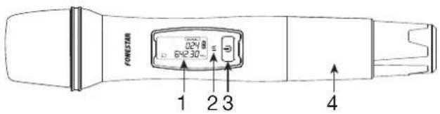
SONAIR-PRO-2M & SONAIR-PRO-2MP TRANSMITTER
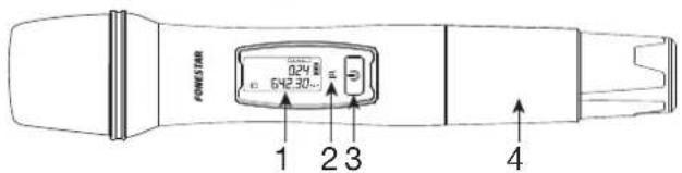
text_image
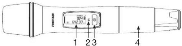
POWERSTAR 0.24V 5x2.30mm 1 2 3 41.- Information display showing the transmission frequency.
2.- IR: IR sensor for synchronisation of the transmission channel (frequency).
3.- ⏻: microphone on/mute/off button. Short press to turn on and long press to turn off the microphone. If it is on, short press to mute the audio and press again to restore it.
4.- Battery holder for 2 AA batteries. The use of rechargeable batteries is also possible.
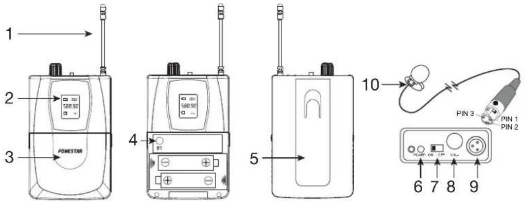
SONAIR-PRO-2P & SONAIR-PRO-2MP TRANSMITTER
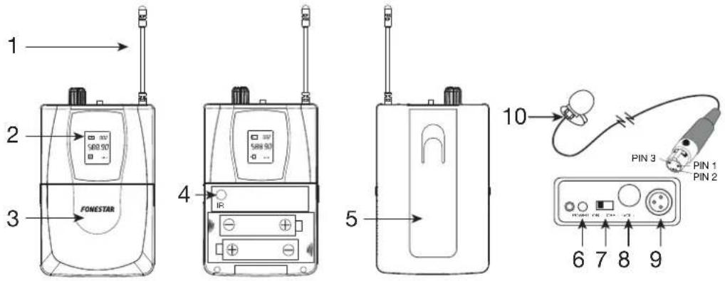
text_image
1 2 3 FONESTAR 4 5 10 PIN 3 PIN 1 PIN 2 6 7 8 91.- RF antenna.
2.- Information display showing the transmission frequency.
3.- Battery holder for 2 AA batteries. The use of rechargeable batteries is also possible.
4.- IR: IR sensor for synchronisation of the transmission channel (frequency).
5.- Attachment clip.
6.- POWER: microphone turn on LED power indicator.
7.- ON/OFF: 3-position microphone power selector: microphone ON, audio mute and microphone OFF.
8.- -VOL+: microphone audio volume control.
9.- Microphone plug, miniXLR connector.
10.- Clip-on belt-pack microphone. miniXLR connector (PIN 1: ground, PIN 2: not connected, PIN 3: signal).
INFORMATION DISPLAYS

text_image
a b c d e f 680.10 MHz 679.70 MHz CH 402 CH 398 VOL 97% VOL 76% c g 024 642.30 MHz a b g c b a g 588.90 LTE CH 002a.- ☐: microphone battery level, ☐: microphone without battery.
b.- Frequency.
c.- Transmission channel.
d.- Volume.
e.- ♣: audio enabled; ♖: audio muted.
f.- (())AB : correct signal Diversity from antenna A or B; (())AB : no signal.
g.- MUTE: microphone audio disabled.
INSTRUCTIONS FOR USE
RECEIVER AND TRANSMITTER SYNCHRONISATION
In order for the communication between receiver and transmitter to be effective, it is necessary that both devices are configured on the same channel (transmission frequency) of the 500 available in the equipment
IMPORTANT:
- Each microphone must be set to a different channel (frequency).
- The use of more than 7 or 8 microphones in the same area in this frequency band 640-690 MHz is not recommended.
- It is not possible to use consecutive channels for the different microphones, it is recommended to leave at least 5 channels free.
The following steps are necessary for synchronisation:
1.- Select a frequency on the receiver by long pressing the rotary control of the channel to be set. This will activate channel editing by turning the same control. Once the desired channel has been selected, press and hold again or wait a few seconds to store the channel in the receiver.
2.- Turn on the microphone to be synchronised and locate its IR sensor. The hand-held microphone has the sensor located above the ⏻ button, and the belt-pack microphone has the sensor located next to the batteries by opening the battery compartment.
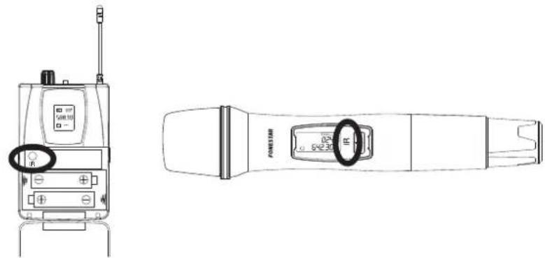
text_image
Technical line drawing of a handheld device with labeled buttons and control panel3.- On the receiver, long press the SYNC button and the IR sensor will start flashing red indicating that it is active.
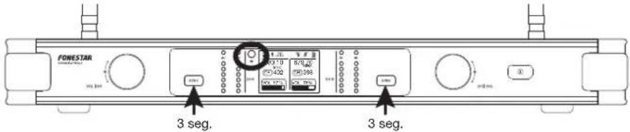
text_image
FONESTAR 3 seg. 3 seg.4.- Place the IR sensor of your microphone in front of the IR sensor of the receiver.
5.- When the receiver's IR is synchronised, the receiver's IR will turn off, all RF channel LEDs will turn on, and the microphone display will show the newly configured channel.
PROBLEMS AND SOLUTIONS
If the RF indicators do not light up, the AF indicators do not light up or the audio does not come through clearly to the receiver, this can be due to several causes:
- the microphone batteries are dead. Replace them with new ones.
- the selected channel or another adjacent channel is being used by other equipment in the vicinity. Select another channel and perform the synchronisation process again.
- the distance between the microphone and the receiver is too great because it is too far away or because the area where you are using the microphone is saturated with signals. You can use different solutions to extend the signal strength by changing the antennas supplied with the equipment and thus extend the coverage distance:
- Antenna amplifier AMP-811 and antenna ADU-830.
- Amplified antenna ADU-823AMP.
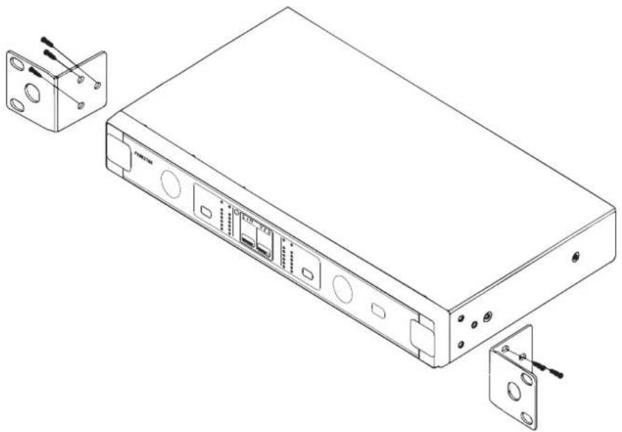
INSTALLATION IN 19" RACK
FONESTAR offers the possibility of installing this receiver in 1 U of a 19" rack cabinet with the supplied mounting brackets.
Its installation is very simple as shown in the image:
natural_image
Line drawing of a network device chassis with ports and connectors, showing external mounting bracket and internal components (no text or symbols)CONNECTION
- Place the receiver at least 1 metre away from the floor, walls or metal surfaces, and in an unobstructed location so that the signal between your antenna and the microphone is as direct as possible.
- Insert the batteries into the microphone and check that they are sufficiently charged. When the microphone detects low power, the battery icon on the transmitter and receiver will indicate this.
- Install the antennas on the receiver and position them vertically for best reception.
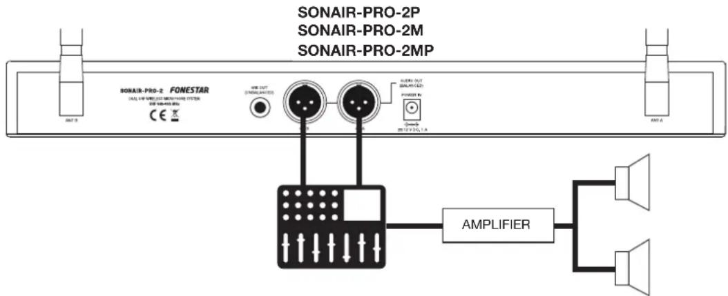
- Connect the balanced audio outputs or the unbalanced mixed signal to the amplifier, mixer, etc.
- Connect the power adapter to the receiver and then to the mains.
- With the volume controls set to minimum, turn on the receiver.
- Next, perform the receiver and transmitter synchronisation process with each microphone to set up their transmit channels. For more information, see section OPERATING INSTRUCTIONS - RECEIVER AND TRANSMITTER SYNCHRONISATION. At this point the RF indicators should be on. If this is not the case, please refer to the INSTRUCTIONS FOR USE - PROBLEMS AND SOLUTIONS section.
- Speak into the microphones and check that the AF indicators light up when you speak and adjust the volume controls so that the red AF indicator does not light up continuously. If your problem is audio related, please consult INSTRUCTIONS FOR USE - PROBLEMS AND SOLUTIONS section.
text_image
SONAIR-PRO-2P SONAIR-PRO-2M SONAIR-PRO-2MP SONAIR-PRO-2 FONESTAR (ALL) 100 MHz (500 MHz) (500 MHz) CE X USB OUT (SINEMALED) CLOTH OUT SINEMALED POWER IN 1.3 V 2.5 V, 1.4 AMPLIFIERTECHNICAL SPECIFICATIONS
| SONAIR-PRO-2P SONAIR-PRO-2M SONAIR-PRO-2MP | |||
| FEATURES Dual | belt-pack wireless microphone. | Dual wireless hand-held microphone with unidirectional dynamic capsule. | Dual hand-held and belt-pack wireless microphone |
| Receiver with colour display of information; transmission channel, battery level in microphone, etc. Radio frequency signal and audio signal indicator.ID Pilot function 16 bit pairing code to avoid interference.Diversity reception with antennas.Transmission of the receiver channel to the microphone with SYNC IR.Selectable channels.Transmission distance greater than 50 m.Great vocal quality.Maximum 7 - 8 microphones at the same time on different channels. | |||
| FREQUENCIES Range 640-690 MHz500 channels | |||
| POWER 30 mW | |||
| RESPONSE 30-20.000 Hz (+/- 2 dB) | |||
| S/N RATIO >96 dB | |||
| OUTPUTS Audio: | 2 balanced, XLR, 0 ~ 250 mV, 600 Ω1 unbalanced mix, 6.3 mm jack, 0 ~ 250 mV, 1 KΩ | ||
| RECEIVER Receiving sensitivity: -95 dBmDistortion: < 0.3%Latency: 3 ms | |||
| MICROPHONES 2 | x belt-pack wireless microphones with clip-on microphone3-pin XLR mini input connector | 2 hand-held wireless microphones with dynamic unidirectional capsule | 1 hand-held wireless microphones with dynamic unidirectional capsule1 belt-pack wireless microphone with clip-on microphone3-pin XLR mini input connector |
| Harmonic radiation: < -50 dBcBattery life (alkaline): 8 - 10 hours approx. | |||
| POWER SUPPLY | Receiver: 12 V DC, 1 A with adapter includedTransmitter microphone: 2 x AA batteries. Supports rechargeable batteries. | ||
| DIMENSIONS Receiver: 420 x 50 x 205 mm depth | |||
| ACCESSORIES 2 | antennas TNC6.3 mm mono jack cable, 1 mAnti-spin ringPower adapterMicrophone batteriesMounts for assembling in 1 U 19" rack | ||
DESCRIPCIÓN
RECEPTOR SONAIR-PRO-2P, SONAIR-PRO-2M Y SONAIR-PRO-2MP
text_image
FONESTAR SINEMA-FINEMA-1 w/o fee 1 2 3 4 5 6 4 3 2 1 7TRANSMISOR SONAIR-PRO-2M Y SONAIR-PRO-2MP
text_image
FONESTAR 0.2V 5HZ30... 1 2 3 4text_image
Technical diagram of a handheld device with labeled ports and control knob, including a 50% speed limit dial.natural_image
Line drawing of a network device chassis with ports and connectors, showing external components and mounting bracket (no text or symbols)CONEXIÓN
text_image
500 x 30" R FUMSTER c. 500 x 30"natural_image
Line drawing of a network device chassis with ports and connectors, showing external mounting bracket and internal components (no text or symbols)CONNEXION
TRANSMISSOR SONAIR-PRO-2M E SONAIR-PRO-2MP
text_image
FONSTRAR 0.2V 642.30Ω 1 2 3 4TRANSMISSOR SONAIR-PRO-2P E SONAIR-PRO-2MP
text_image
1 2 3 FONESTAR 4 IR 5 10 PIN 3 PIN 1 PIN 2 6 7 8 9natural_image
Technical line drawing of a handheld device with front and side views (no text or symbols)PROBLEMAS E SOLUÇÕES
natural_image
Line drawing of a network device chassis with ports and connectors, showing external hardware components (no text or symbols)LIGAÇÃO
SIMPLIFIED EU DECLARATION OF CONFORMITY
FONESTAR SISTEMAS S.A. hereby declares that the Dual UHF wireless microphone system (ID pilot and Diversity) SONAIR-PRO-2P, SONAIR-PRO-2M and SONAIR-PRO-2MP comply with the Directive 2014/53/EU.
The complete text of the EU Declaration of Conformity is available at the following internet address:
fonestar.com/SONAIR-PRO-2P
fonestar.com/SONAIR-PRO-2M
fonestar.com/SONAIR-PRO-2MP
ES
fonestar.com/SONAIR-PRO-2P
fonestar.com/SONAIR-PRO-2M
fonestar.com/SONAIR-PRO-2MP
FR
DÉCLARATION UE DE CONFORMITÉ SIMPLIFIÉE
fonestar.com/SONAIR-PRO-2P
fonestar.com/SONAIR-PRO-2M
fonestar.com/SONAIR-PRO-2MP
PT
fonestar.com/SONAIR-PRO-2P
fonestar.com/SONAIR-PRO-2M
fonestar.com/SONAIR-PRO-2MP
www.fonestar.com