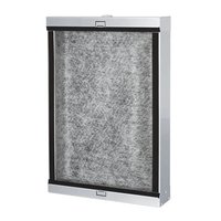
TDO-45 - Speaker FoneStar - Free user manual and instructions
Find the device manual for free TDO-45 FoneStar in PDF.


User questions about TDO-45 FoneStar
0 question about this device. Answer the ones you know or ask your own.
Ask a new question about this device
Download the instructions for your Speaker in PDF format for free! Find your manual TDO-45 - FoneStar and take your electronic device back in hand. On this page are published all the documents necessary for the use of your device. TDO-45 by FoneStar.
USER MANUAL TDO-45 FoneStar
natural_image
Top-down view of an electronic circuit board with multiple speaker components and wiring (no visible text or symbols)INSTRUCTION MANUAL/MANUAL DE USUARIO/MODE D'EMPLOI/MANUAL DE INSTRUÇÕES
DESCRIPTION
The TDO-45 speaker has been designed to provide optimal sound quality when installed together with the TDO-45BOX box. Although direct installation is possible, this configuration may result in a loss of sound quality.
- Invisible speaker with 70 and 100 V line transformer.
- Installation on drywall panels, with accessories for installation on 12.5 mm boards (without TDO-45BOX) or 15 mm boards (with TDO-45BOX) both wall and ceiling.
- Plays the sound through the vibration of the radiating surface.
- Non-directional sound.
- Long lifespan.
INSTALLATION
WARNING
- This product should not be installed within existing building structures unless it is certain that no electrical wires, water or gas pipes, or support beams will be cut.
- Ensure that all mounting surfaces of the installation can support the weight of the product and mounting accessories.
- Before proceeding with the installation, it is recommended that there be acoustic padding behind the wall or ceiling where the TDO-45 is to be installed to reduce backward radiated sound and enhance the sound by projecting it in the direction of the speakers.
- After installation, avoid pushing on the surface in front of the loudspeaker as this may crack the plaster and/or damage the speaker.
- Please note that vibration energy may inevitably be transferred through the walls of the building
TDO-45
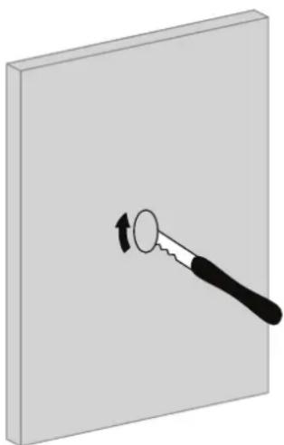
1
Make a hole in the wall of approximately 5 cm in diameter.
natural_image
Illustration of a hand holding a circular object with an arrow indicating rotation (no text or symbols)2
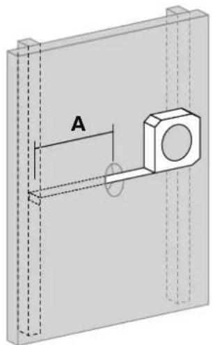
Check that there is adequate space behind the surface to allow the speaker to be installed between the studs.
natural_image
Technical diagram of a mechanical assembly with labeled component A (no text or symbols beyond label)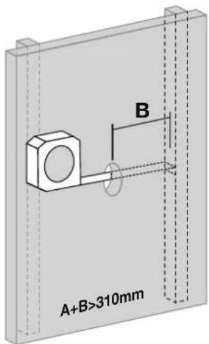
text_image
A+B>310mm B3
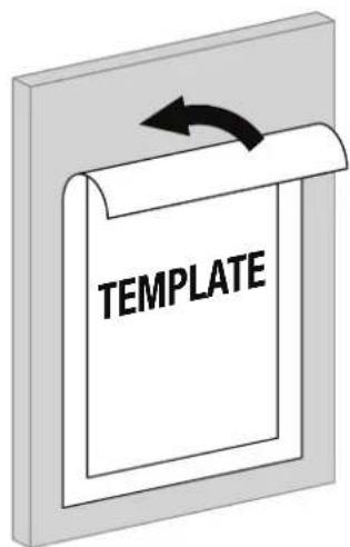
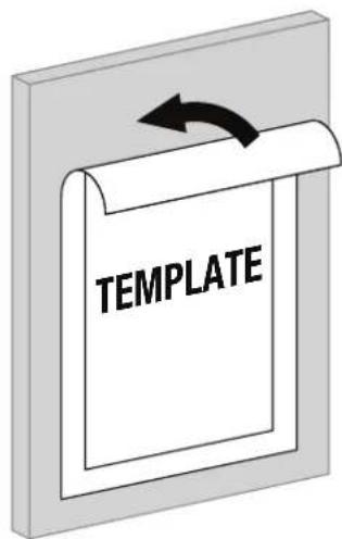
Make the hole in the wall using the template as a guide.
text_image
TEMPLATE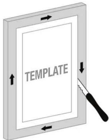
text_image
TEMPLATE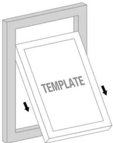
text_image
TEMPLATE4
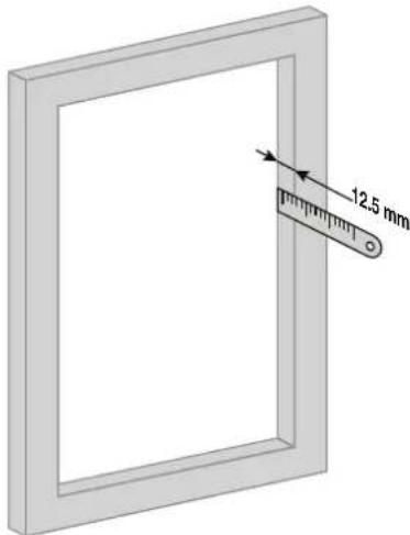
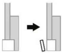
It is essential that the speaker is flush once installed, so it is recommended to use a drywall surface with a thickness of 12.5 mm. Depending on the surface thickness, it may be necessary to adjust the provided spacers.
text_image
12.5 mmEN
- If the surface is thinner, cut the appropriate amount of foam from the spacers to ensure the speaker is perfectly aligned with the surface.
- If the surface thickness exceeds 12.5 mm, additional foam should be added to the spacers to achieve a proper fit.
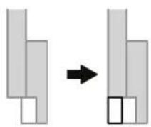
NOTE: The width of the plasterboard surface should be between 10 and 35 mm. If this is not the case, special dowels or spacers may be required.
5
Attach each spacer to one of the corners of the hole using a screw, ensuring it is foam rubber area protrudes as shown in the image detail.
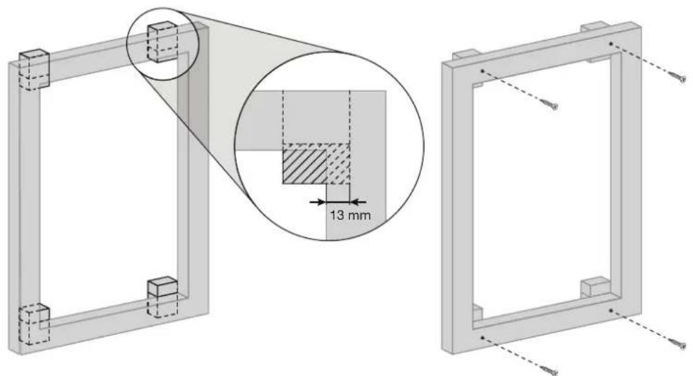
natural_image
Technical drawing of a mechanical frame assembly with an inset showing a 13 mm dimension detail (no text or symbols present)6
Connect the corresponding cables. It is recommended to perform a sound test at a moderate volume to verify that the connections are correctly made and that the sound is properly reproduced.

natural_image
Diagram of a mechanical clamp or tool inserted into a rectangular frame, no text or symbols present7
Secure the speaker by screwing each corner to the foam area of the spacer. It is important to ensure that there is a 2 mm gap between the TDO-45 and the drywall.
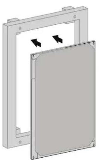
natural_image
3D diagram of a mechanical component with two rectangular parts and directional arrows indicating movement (no text or symbols)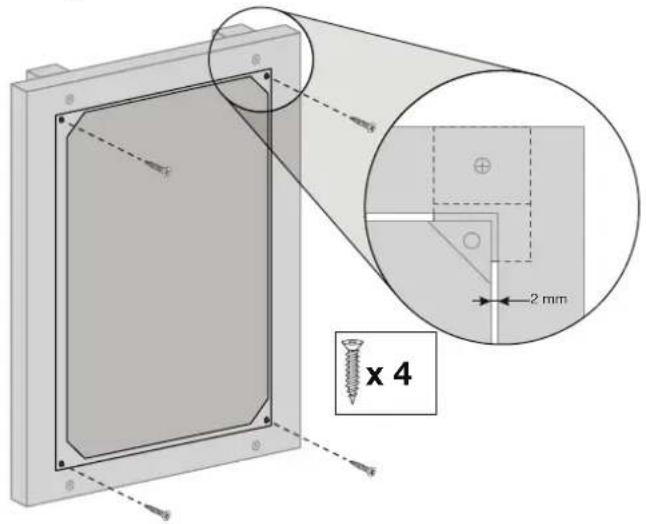
text_image
x 4 2 mm8
Check that the TDO-45 is perfectly aligned and flush with the wall.
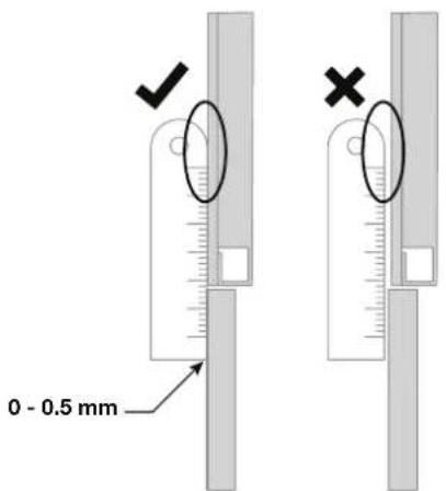
text_image
0 - 0.5 mmNOTE: Before proceeding with installation, it is recommended to have acoustic filler behind the wall or ceiling where the TDO-45 will be installed to reduce the sound radiated backward. If detected, please check the installation and fix the elements correctly.
9
Plaster the edges without covering the speaker and allow it to dry completely.
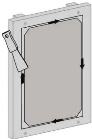
natural_image
Pure mechanical diagram showing a rectangular frame with internal flow arrows, no text or symbols presentPlace a fiberglass mesh over the surface, fully covering the area, including the screws.
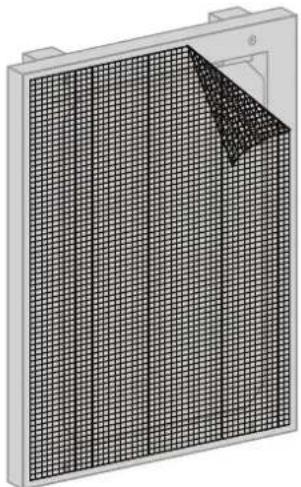
natural_image
3D rendering of a grid-patterned panel or panel with a corner edge, no visible text or symbols11
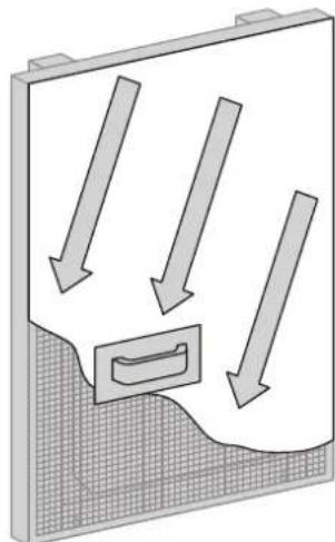
Apply putty over the mesh, ensuring full coverage. It is recommended to plaster at least 1 m^2 around the TDO-45. Once dry, remove any excess putty. The applied layer should not exceed 2 mm in thickness.
natural_image
Diagram showing airflow or fluid flow with arrows pointing downward and a rectangular object inside, no text or symbols present.12
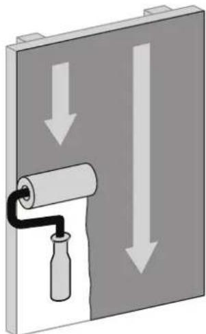
Paint over the putty layer once it is completely dry.
natural_image
Diagram showing a roller being inserted into a wall with downward arrows indicating force or direction (no text or symbols)NOTE: It is recommended to use acrylic or water-based paint, which does not alter the acoustics of the TDO-45 and is compatible with the plaster finish. Wallpapers can also be applied. It is important to avoid dense materials or materials with properties that may alter the performance of the speaker.
1
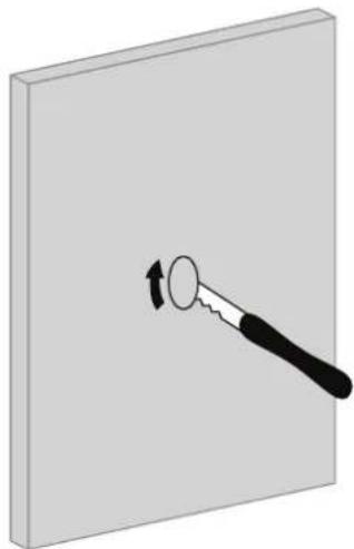
Make a hole in the wall of approximately 5 cm in diameter.
natural_image
Illustration of a hand holding a circular object with an arrow indicating rotation (no text or symbols)2
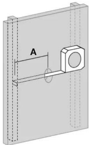
Check that there is adequate space behind the surface to allow the speaker to be installed between the studs.
natural_image
Technical diagram of a mechanical assembly with labeled component A (no text or symbols beyond label)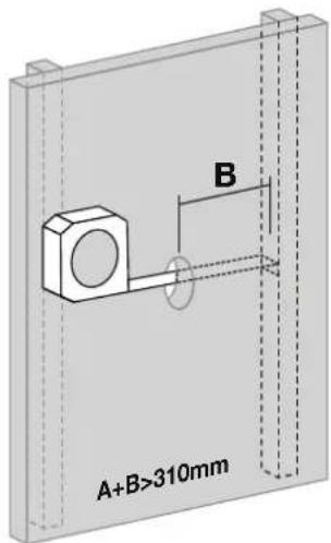
text_image
A+B>310mm B3
Make the hole in the wall using the template as a guide.
text_image
TEMPLATE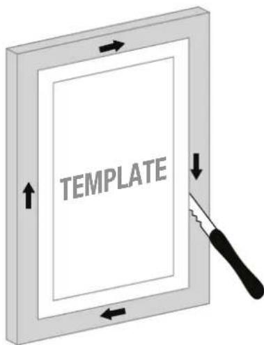
text_image
TEMPLATE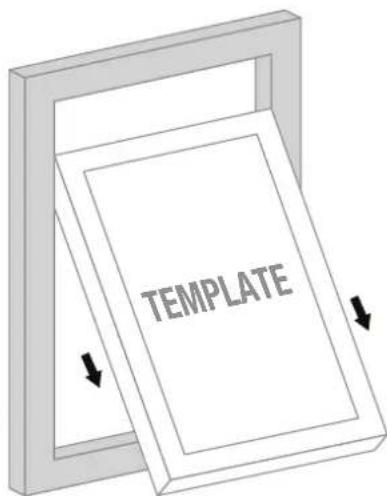
text_image
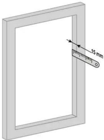
TEMPLATEIt is essential that the speaker is flush once installed, so it is recommended to use a drywall surface with a thickness of 15 mm. Depending on the surface thickness, spacers (not included) may be necessary.
natural_image
Diagram of a rectangular frame with a ruler inserted, showing a 15 mm measurement on the side (no text or symbols beyond measurement label)4.1
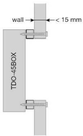
If the surface is thinner than 15 mm, spacers should be placed between the drywall and the TDO-45BOX, adjusting them as needed until reaching a thickness of 15 mm.
text_image
wall TDO-45BOX < 15 mm4.2
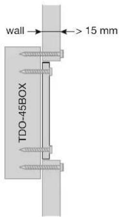
In case the thickness of the surface is more than 15 mm, spacers should be placed between the TDO-45 and the TDO-45BOX to increase the thickness and achieve a proper fit. The spacers shall be placed on the black rubber of the box.
text_image
wall TDO-45BOX > 15 mm5
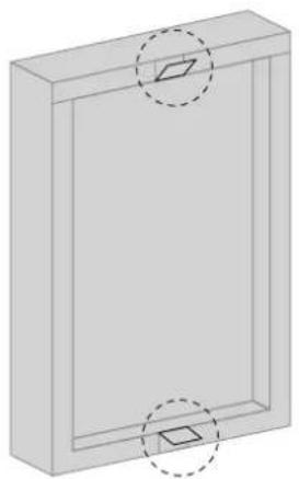
Open the flaps of the box that will help to position it on the drywall.
natural_image
3D diagram of a rectangular frame with two circular holes and a central square hole, no text or symbols present.6
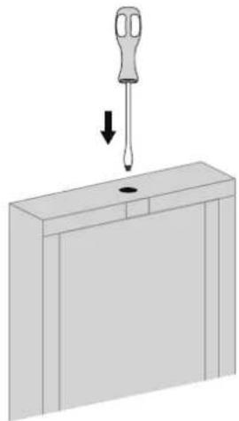
Make a hole in the cable entry point using a sharp object.
natural_image
Diagram of a screwdriver inserted into a component with a downward arrow indicating force or direction (no text or symbols)7
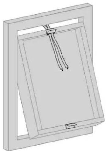
Place the TDO-45BOX over the edge of the hole and pass the cables through the hole until they are inside the box.
natural_image
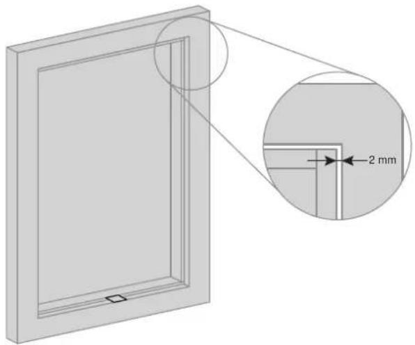
3D diagram of a rectangular frame with internal cable or wire structures, no text or symbols presentCenter the TDO-45BOX on the surface and position the tabs to secure it. It is important to ensure a 2 mm gap between the box and the drywall.
natural_image
Diagram of a door frame with an inset showing a 2 mm dimension (no text or symbols present)9
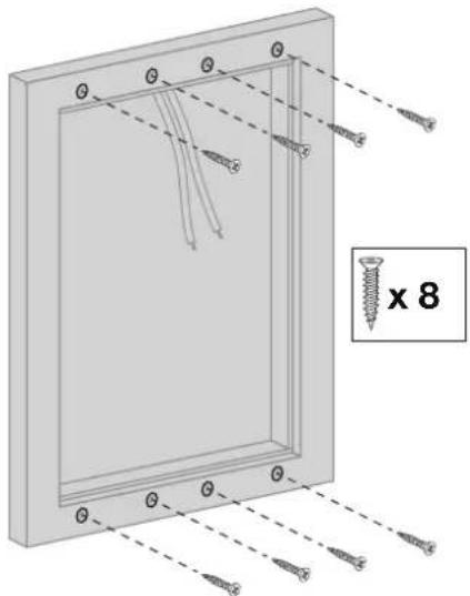
Screw the enclosure to the surface reliably and securely. It is recommended to place the screws as shown in the picture.
text_image
x 810
Connect the corresponding cables. A sound test at a moderate volume is recommended to verify that the connections are correctly made and that the sound is properly reproduced.
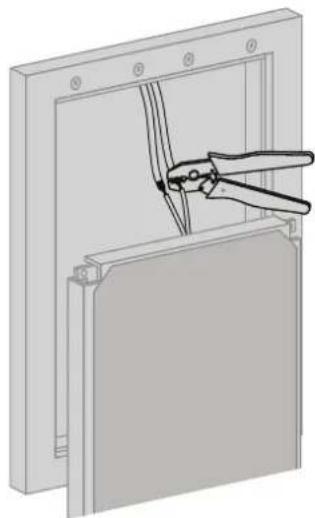
natural_image
Diagram of a hand using pliers to cut or install a rectangular panel (no text or symbols visible)11
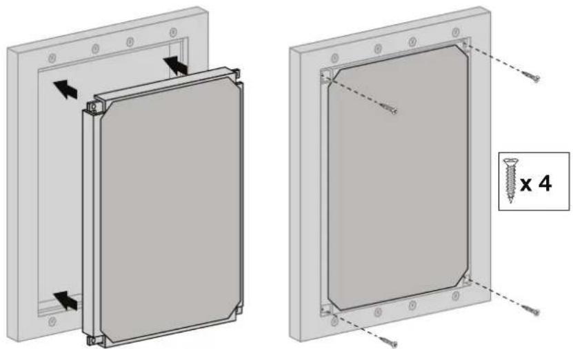
Secure the speaker by screwing each corner to the TDO-45BOX.
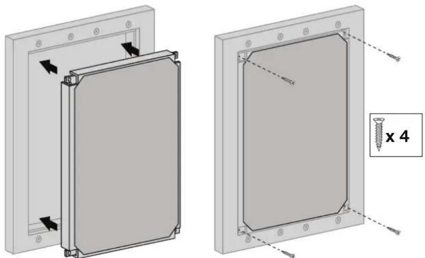
natural_image
Technical diagram showing two views of a rectangular panel with screw fasteners and mounting holes, no text or symbols present.12
Check that the TDO-45 is perfectly aligned and flush with the wall.
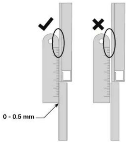
text_image
0 - 0.5 mmNOTE: Before proceeding with installation, it is recommended to have acoustic filler behind the wall or ceiling where the TDO-45 will be installed to reduce the sound radiated backward. If detected, please check the installation and fix the elements correctly.
13
Apply plaster joint filler to the edges until they are completely covered, without covering the speaker. Allow to dry completely and remove excess before proceeding to the next step.
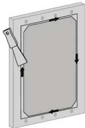
natural_image
Pure mechanical diagram showing a rectangular frame with internal arrows and a handle, no text or symbols present.
14
Place a fiberglass mesh over the surface, fully covering the area, including the screws.

natural_image
3D rendering of a grid-patterned panel or panel with a corner detail (no text or symbols visible)15
Apply putty over the mesh, ensuring full coverage. It is recommended to plaster at least 1 m^2 around the TDO-45. Once dry, remove any excess putty. The applied layer should not exceed 2 mm in thickness.
natural_image
Diagram showing downward arrows pointing to a rectangular object with a curved handle, set against a textured background (no text or symbols)16
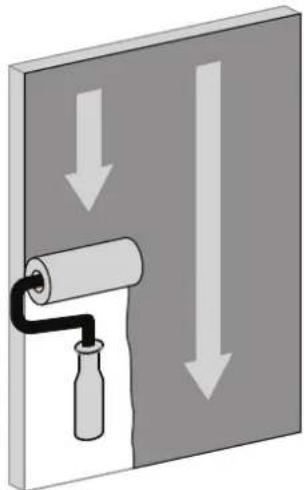
Paint over the putty layer once it is completely dry.
natural_image
Diagram showing a roller being inserted into a wall with downward arrows indicating force or direction (no text or symbols)NOTE: It is recommended to use acrylic or water-based paint, which does not alter the acoustics of the TDO-45 and is compatible with the plaster finish. Wallpapers can also be applied. It is important to avoid dense materials or materials with properties that may alter the performance of the speaker.
TECHNICAL SPECIFICATIONS
| TDO-45 | |
| FEATURES Invisible loudspeaker with 70 and 100 V line transformerPlasterboard panel installation, with accessories for installation in 12.5 mm plasterboard.Sound is produced via radiating surface vibration.Non-directional sound.Long product life. | |
| POWER 60 W maximum, 40 W RMS | |
| DRIVERS 4 | |
| RESPONSE 140-20,000 Hz | |
| IMPEDANCE 40 W RMS@100V (250 Ω) | |
| SENSITIVITY 90 dB ±3 dB at1 W/1 m | |
| DISPERSION 180° | |
| MATERIAL Aluminium | |
| DIMENSIONS 300 x 400 x 50 mm depth | |
| WEIGHT 1.45 kg | |
| ACCESSORIES 1 cutting template4 MDF wood installation dowels with foam8 screws | |
| OPTIONAL TDO-45BOX: installation box | |
| TDO-45BOX | |
| FEATURES Installation box for invisible loudspeaker TDO-45. | |
| DIMENSIONS 304 x 450 x 71 mm depth | |
| WEIGHT 1.5 kg | |
| ACCESSORIES 8 Drywall screws 50 mm4 Self-tapping screws 20 mm1 Installation template 306 x 406 mm | |
DESCRIPCIÓN
natural_image
Illustration of a hand holding a circular object with an arrow indicating rotation (no text or symbols)2
text_image
A B A+B>310mm3
natural_image
Technical drawing of a mechanical frame with an inset showing a 13 mm dimension detail (no text or symbols present)6
natural_image
Diagram of a window frame with a tool inserted into the frame, no text or symbols present7
natural_image
3D diagram of a rectangular frame with two arrows indicating directional movement or force, no text or symbols present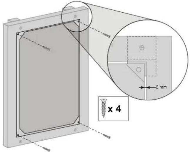
text_image
x 4 2 mm8
natural_image
Diagram of a mechanical component with directional arrows indicating movement or force (no text or symbols present)ES
10
natural_image
3D rendering of a grid-patterned panel or solar panel with a corner detail (no text or symbols visible)11
natural_image
Diagram showing airflow or fluid flow through a container with arrows indicating direction (no text or symbols)12
natural_image
Diagram showing a roller being inserted into a wall with downward arrows indicating force or direction (no text or symbols)natural_image
Illustration of a hand holding a circular object with an arrow indicating rotation (no text or symbols)2
natural_image
Technical diagram of a mechanical assembly with labeled component A, showing alignment and mounting features (no text or symbols beyond label)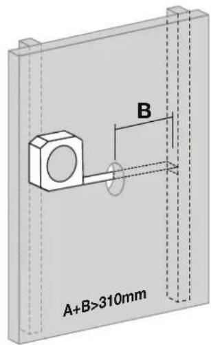
text_image
A+B>310mm B3
natural_image
Diagram of a rectangular frame with a ruler inserted, showing a 15 mm measurement on the side (no text or symbols beyond measurement label)4.1
text_image
pared TDO-45BOX < 15 mm4.2
natural_image
3D diagram of a rectangular enclosure with two dashed circular highlights on the top and bottom (no text or symbols)6
natural_image
Diagram of a screwdriver inserted into a component with a downward arrow indicating force or direction (no text or symbols present)7
natural_image
3D diagram of a rectangular frame with internal vertical panels and two horizontal connectors (no text or symbols)ES
8
natural_image
Diagram of a door frame with an inset showing a 2 mm dimension detail (no text or symbols present)9
natural_image
Technical diagram of a mechanical assembly with screws and a 8x magnified section (no text or symbols)10
natural_image
Technical illustration of a mechanical assembly with a tool inserted into a frame (no text or symbols)11
natural_image
Technical diagram showing two views of a rectangular panel with screw fasteners and mounting holes, no text or symbols present.12
natural_image
Pure mechanical diagram showing a rectangular frame with arrows indicating direction, no text or symbols presentnatural_image
3D rendering of a grid-patterned panel or panel with a corner detail (no text or symbols visible)15
natural_image
Diagram showing directional arrows pointing downward onto a textured surface with a rectangular object inside (no text or symbols)16
natural_image
Diagram showing a roller being inserted into a wall with downward arrows indicating force or direction (no text or symbols)natural_image
Illustration of a hand holding a circular object with an arrow indicating rotation (no text or symbols)2
text_image
A B A+B>310mm3
natural_image
Technical drawing of a mechanical frame assembly with an inset showing a 13 mm dimension detail (no text or symbols present)6
natural_image
Diagram of a metal frame with a pair of pliers inserted into a rectangular panel (no text or symbols)7
natural_image
3D diagram of a mechanical frame with two arrows indicating rotation or movement, no text or symbols present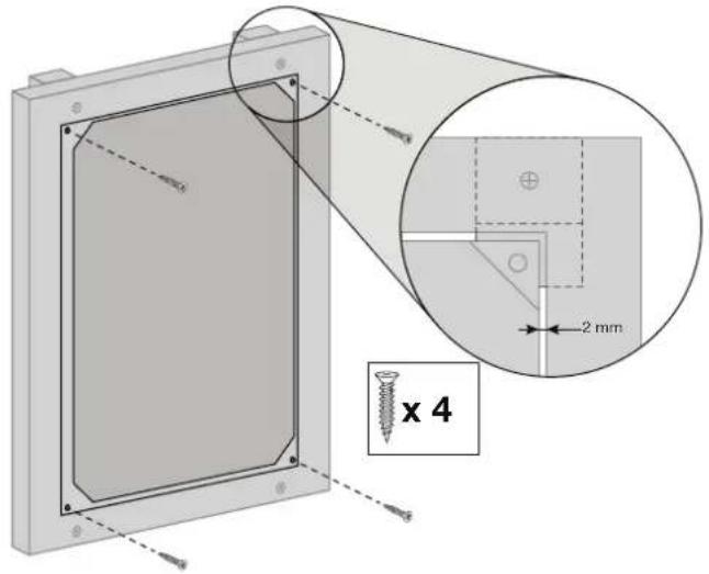
text_image
2 mm x 48
natural_image
Diagram of a mechanical component with directional arrows indicating flow or movement (no text or symbols)
10
natural_image
3D rendering of a grid-patterned panel or panel with a corner edge, no text or symbols visible11
natural_image
Diagram showing directional arrows pointing downward onto a textured surface with a rectangular object inside (no text or symbols)12
natural_image
Diagram showing a roller being inserted into a wall with downward arrows indicating force or direction (no text or symbols)natural_image
Illustration of a hand holding a circular object with an arrow indicating rotation (no text or symbols)2
natural_image
Technical diagram of a mechanical assembly with labeled component A (no text or symbols beyond label)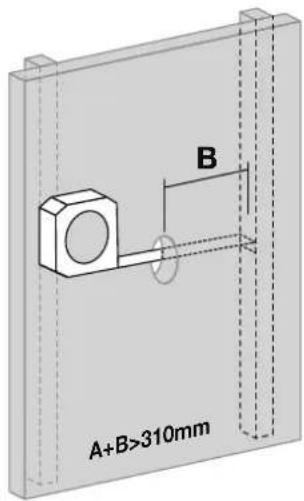
text_image
A+B>310mm B3
natural_image
Diagram of a rectangular frame with a ruler inserted, showing a 15 mm measurement on the side (no text or symbols beyond measurement label)4.1
natural_image
3D diagram of a rectangular frame with two circular annotations highlighting internal features (no text or symbols)6
natural_image
Diagram of a screwdriver inserted into a rectangular box with a downward arrow indicating force or direction (no text or symbols present)7
natural_image
3D diagram of a rectangular frame with internal cable and connectors, no text or symbols present

natural_image
Diagram of a door frame with an inset showing a 2 mm dimension measurement (no text or symbols present)
natural_image
Technical diagram of a mechanical assembly with screws and a 8x magnified view (no text or symbols)
natural_image
Diagram of a mechanical assembly with a tool inserted into a frame, showing no text or symbols.11
natural_image
Technical diagram showing two views of a rectangular panel with screw fasteners and mounting holes, no text or symbols present.12
natural_image
Pure mechanical diagram showing a rectangular frame with arrows indicating direction, no text or symbols present
14
natural_image
3D rendering of a grid-patterned panel or panel with a corner detail (no text or symbols visible)15
natural_image
Diagram showing directional arrows pointing downward onto a textured surface with a rectangular object inside (no text or symbols)16
natural_image
Diagram showing a roller being inserted into a wall with downward arrows indicating force or pressure (no text or symbols)natural_image
Illustration of a hand holding a circular object with an arrow indicating rotation (no text or symbols)2
text_image
A B A+B>310mm3
natural_image
Diagram of a rectangular frame with a ruler and measurement label (no text or symbols beyond measurement)PT
natural_image
Technical diagram showing two views of a mechanical frame with a magnified inset highlighting a 13 mm feature (no text or symbols present)6
natural_image
Diagram of a window frame with a hand using a tool to cut or install a panel (no text or symbols present)7
natural_image
3D diagram of a rectangular frame with two arrows indicating rotation or movement, no text or symbols present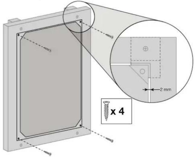
text_image
2 mm x 48
natural_image
Diagram of a mechanical component with directional arrows indicating movement or force (no text or symbols present)
10
natural_image
3D rendering of a grid-patterned solar panel mounted on a rectangular base (no text or symbols visible)11
natural_image
Diagram showing airflow or fluid flow with arrows pointing downward and a rectangular object inside, no text or symbols present.12
natural_image
Diagram showing a roller being inserted into a wall with downward arrows indicating force or direction (no text or symbols)natural_image
Illustration of a hand holding a circular object with an arrow indicating rotation (no text or symbols)2
text_image
A B A+B>310mm3
natural_image
Diagram of a rectangular frame with a ruler inserted, showing a 15 mm measurement on the side (no text or symbols beyond measurement label)4.1
natural_image
3D diagram of a rectangular enclosure with two circular annotations highlighting areas of interest (no text or symbols present)6
natural_image
Diagram of a screwdriver inserted into a rectangular box with a downward arrow indicating force or insertion (no text or symbols present)7
natural_image
3D diagram of a rectangular frame with internal wires and connectors, no text or symbols presentPT
8
natural_image
Diagram of a door frame with an inset showing a 2 mm dimension detail (no text or symbols present)9
natural_image
Technical diagram of a mechanical assembly with screws and a 8x magnified section (no text or symbols)10
natural_image
3D diagram of a mechanical assembly with a tool inserted into a frame, no text or symbols present11
Fixar a coluna aparafusando cada canto na TDO-45BOX.
natural_image
Technical diagram showing two views of a rectangular panel with screw fasteners and mounting holes, no text or symbols present.12
natural_image
Pure mechanical diagram showing a rectangular frame with directional arrows and mounting points (no text or symbols)
14
natural_image
3D rendering of a grid-patterned panel or panel with a corner detail (no text or symbols visible)15
natural_image
Diagram showing downward arrows pointing to a rectangular object with a textured base (no text or symbols)16