
AC1356 - Industrial Automation IFM - Free user manual and instructions
Find the device manual for free AC1356 IFM in PDF.
| Product type | AS-i controller / industrial gateway |
| Brand | IFM Electronic |
| Model | AC1356 |
| Power supply | 24 V DC (20...30 V SELV), galvanically isolated, UL fuse max. 5 A (0...20 Veff) or 100 Vpeak (20...30 Veff) |
| Programming interfaces | RS232C (4800...115200 baud, max. 20 m), Ethernet 10/100 Mbps (TCP/IP, Modbus TCP, UDP, RJ45), Profibus DP (9600 baud...12 Mbaud) |
| AS-i masters | 1 or 2 AS-i masters (depending on AS-i 3.0 version) |
| Main functions | Data exchange control with sensors/actuators, signal preprocessing, autonomous controller, gateway to higher-level control system |
| Display and indicators | Screen with contrast adjustment, LEDs PWR/COM, PROJ, CONF/PF, ETH NET, PROFIBUS |
| Mounting | On 35 mm profile rail, IP20, in protected environment (electrical cabinet), avoid condensation, dust, vibrations, shocks |
| Electrical connection | Terminals +24 V and 0 V for power supply, FE terminal for earth, do not connect negative potentials to each other or to FE |
| Menu navigation | MENU button, up/down navigation buttons, right button for contrast, password (factory: user mode, password CE01 to reset) |
| Safety | Galvanically isolated power supply, galvanic isolation of interfaces, password to limit configuration access |
| Maintenance and cleaning | Keep ventilation openings clear, clean with a dry cloth, avoid solvents and abrasive products |
| Weight and dimensions | Not specified in the manual |
| Spare parts and repairability | No spare parts listed; contact the manufacturer for repair |
| General information | User manual available for download in PDF, 26 pages, languages: FR, DE, EN |
Frequently Asked Questions - AC1356 IFM
User questions about AC1356 IFM
0 question about this device. Answer the ones you know or ask your own.
Ask a new question about this device
Download the instructions for your Industrial Automation in PDF format for free! Find your manual AC1356 - IFM and take your electronic device back in hand. On this page are published all the documents necessary for the use of your device. AC1356 by IFM.
USER MANUAL AC1356 IFM
Function and features
- The controller e integrates one or two AS-i masters (AC1355/AC1356, both in accordance with the AS-i version 3.0), a mini controller, an Ethernet interface and a Profibus DP interface.
- It controls the exchange of data to the sensor/actuator level
- processes the peripheral data in the integrated processor (signal preprocessing)
- works as stand-alone controller with exchange of data to the PC (visualisation)
- communicates with the higher control level (in the gateway mode)
Programming interface RS232C
- Baud rate 4800 to 115,200 baud
- Max. distance between controller _e and PC: 20 m
- Potential separation from the controller _e power supply
- Programming cable E70320 for connection to PC required
Ethernet programming interface
- 10 Mbps and 100 Mbps
- TCP/IP - Transport Control Protocol/ Internet Protocol
Modbus TCP (only as diagnostic interface) The outputs are not reset when the connections are disconnected (no watchdog function) - UDP - User Datagram Protocol
- Support of the CoDeSys programming functions and the global network variables
- RJ45, Twisted-Pair
Profibus-DP interface
- baud rate 9600 baud to 12 MBit/s
- max. distance between controller e and DP master: depending on the baud rate
- potential separation from the controller e power supply
- up to 31 controllers connected in parallel per segment
- pin connection: pin 3: signal B, pin 8: signal A
Installation
Fix the controller e onto a 35 mm DIN rail which has an electrically safe ground connection. The protection rating of the unit is IP20, therefore it should be mounted in a protected location (e.g. control cabinet).

Ensure a condensation-free environment. Avoid excessive dust, vibration and shock. The air circulation through the vents must not be impeded.
Avoid installation in direct vicinity of frequency inverters.
Electrical connection
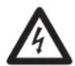
Disconnect the installation from power. Connect the unit as indicated on the terminals. Never connect the minus potentials to each other or the minus potentials to the FE connection.
Ensure an electrically safe ground connection between AS-i controller (terminal FE) and ground connection of the unit.
Supply the controller with a 24 V DC voltage (20...30 V PELV), e.g. from the 24 V power supply DN2011 of ifm electronic. The connection is made to the terminals +24 V and 0 V.
Operating and indicating elements
Information concerning the state of the master (AC1355)/masters /AC1356) and the connected system is given via three diagnostic LEDs on the controllere.
- LED PWR/COM lights: AS-i voltage present, at least one slave was detected
- LED PWR/COM flashes: AS-i voltage present, but no slave was detected correctly
- LED PROJ lights: Projection mode active, the configuration monitoring is deactivated
-
LED PROJ flashes: Projection mode active, changeover to protected mode not possible as a slave with the address 0 is connected
-
LED CONF/PF lights: Projected and current configuration do not match
- LED CONF/PF flashes: Periphery fault on at least one connected slave
- LED ETH NET: Exchange of data via the Ethernet interface
- LED PROFIBUS lights: Bus error Profibus DP
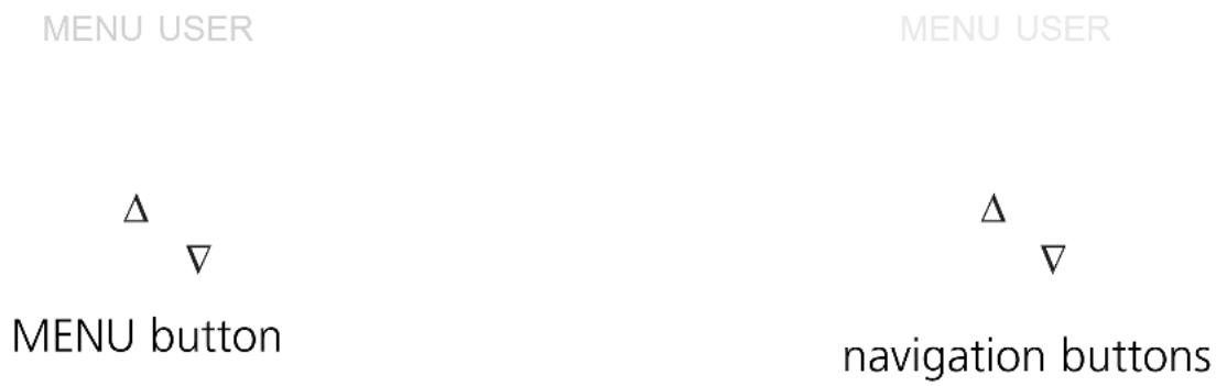
Contrast setting
The contrast can be directly changed by simultaneously pressing the right button and the -button (too bright) or the -button (too dark).
increase contrast
decrease contrast
Operation
To operate an AS-i system a special AS-i power supply is required (e.g. AC1216). The AS-i power supply supplies the yellow AS-i cable with energy and implements a data decoupling to the voltage regulator of the power supply. Standard switched-mode power supplies would consider the AS-i data signals as interference signals and suppress them.

Disconnect the power supply before connecting the controllere.

The AS-i system is operated ungrounded. AS-i + and AS-i - are to be symmetrical to the ground potential of the installation.
Ensure a low resistance connection of the symmetry point of the AS-i power supply (terminal shield) to the ground of the installation.
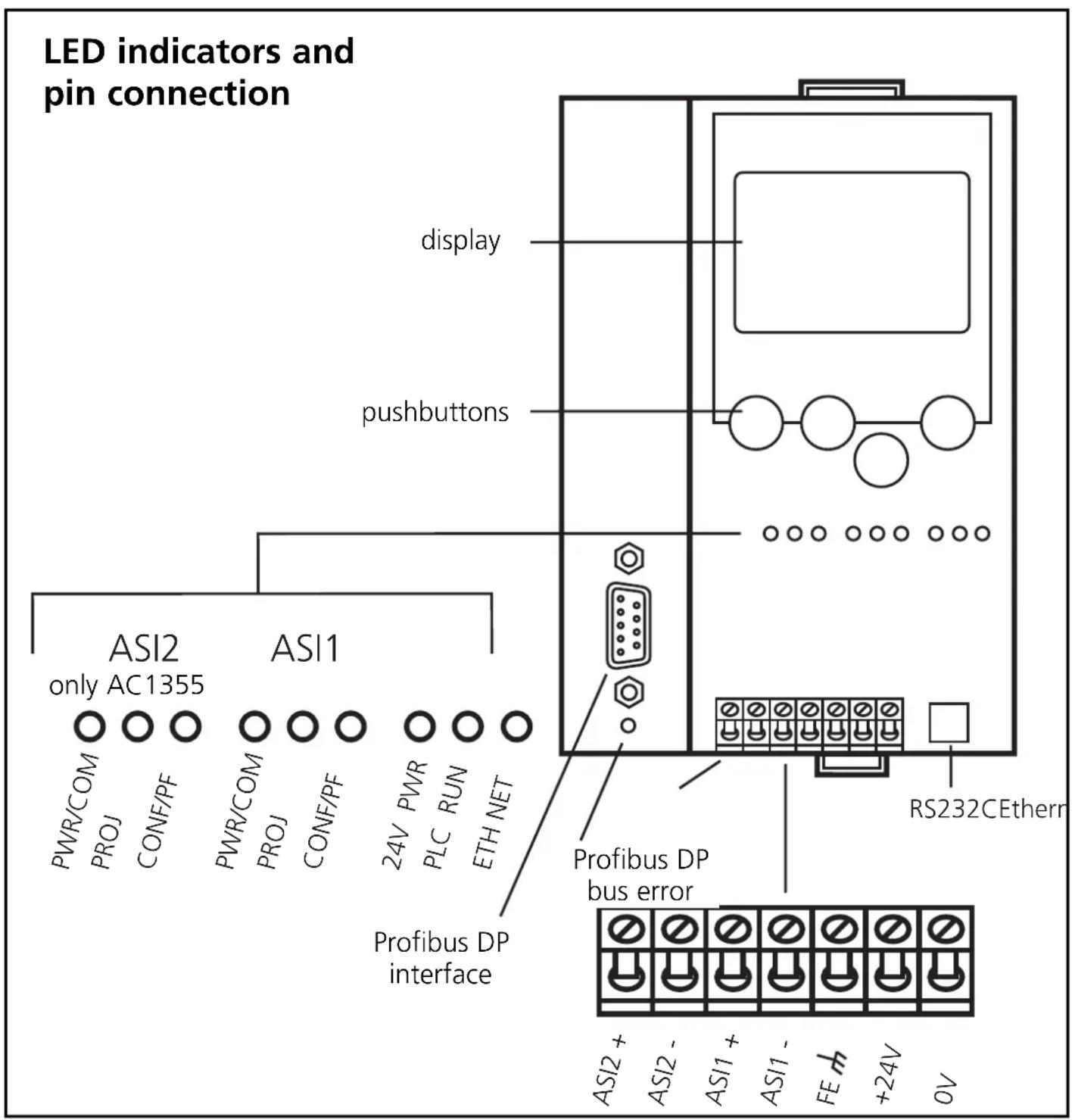
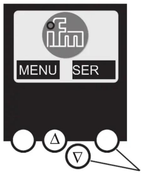
Menu overview
Open the main menu by pressing the left button "MENU" in the start display.
To navigate within a menu point press the button or .
Press the buttons simultaneously to switch between the German and English menu.
Password
Important:
When selecting 'Password' in the 'System Setup' menu, operation can be restricted or released.
When delivered, the device is in the user mode. By entering an invalid password (e.g. 1000) all menu items that allow settings to be changed will be blocked.
By entering the password 'CE01' the user mode is enabled again.
The password is stored non-volatily by the System Setup / Store System menu item.
Menu navigation
By pressing the left button in the start display (AS-i error diagnostics) the main menu is opened. The two buttons in the middle allow scrolling through the menu.
O Quick Setup (summary of the menu items for a basic configuration)
'Teach in' of the current AS-i configuration (Project all)
Settings of the fieldbus interface (option)
O PLC Setup (settings of the optional PLC)
Switch the gateway mode on or off (operation without PLC)
Start and stop the PLC in the controller (if used)
plc project name, version, date and author
O Slave Lists (Checking of the addresses of the connected AS-i slaves)
Indication of the list of detected slaves (LDS)
Indication of the list of projected slaves (LPS)
Indication of the list of activated slaves (LAS)
Indication of the list of periphery faults in AS-i slaves (LPF)
O Address Slave (Programming of the addresses of the connected AS-i slaves)
Readdressing of an AS-i slave connected to the controllere
Automatic addressing of new AS-i slaves to the next free address (easy start-up)
O Diagnostics (diagnostics of the connected AS-i networks)
Counting the AS-i voltage dips since power on of the controle
Counting the AS-i configuration errors since power on of the controle
Verify the fault rate of the AS-i messages of the connected AS-i system
Indication of the number of connected AS-i slaves and the cycles per second
List of the AS-i slaves with faulty messages since power on of the controllere
Reset of the error counter
Indication of the maximum system cycle time
Reading the diagnostic information of Safety-at-Work monitors
O Master Setup (information on the AS-i master system)
'Teach in' of the current AS-i configuration (project all)
Changeover to the projection mode: configuration of the AS-i system
Changeover to the protected mode: normal operation (master monitors configuration)
Enable the automatic AS-i slave addressing in the protected mode
Deactivation of the AS-i reset during the change to the protected mode
O Fieldbus Setup(Setting of the optional fieldbus interface)
Setting of the device address of the controller_e in the higher-level fieldbus
If necessary further settings of the higher-level fieldbus
O Slave Info (Details about the connected AS-i slaves)
Indication of the digital or analogue inputs / outputs of the connected AS-i slaves
Indication of the parameters of the connected AS-i slaves
Indication of the ID and IO codes of the connected AS-i slaves
Indication of the transmission errors to the connected AS-i slaves
O Slave Setup (settings of the connected AS-i slaves)
V Forcing the parameters of the connected AS-i slaves
Forcing the digital or analogue inputs / outputs of a connected AS-i slave
O System Setup (Device settings of the controller e)
Store the current system settings
Setting of the baud rate of the serial programming interface
Setting of the parameters of the Ethernet programming interface (option)
Enter the new password to disable or enable the menu functions
Update the controller e operating system (special software required!)
Reset to the factory settings of the controller_e
O System info (Device information)
hardware and operating system version numbers of this controllere
type and version number of the optional fieldbus interface
Limited voltage / Current
The device shall be supplied from an isolating transformer having a secondary Listed fuse rated either
a) max 5 amps for voltages 0 20 Vrms (0 28.3Vp) or
b) 100Vp for voltages of 20~30 Vrms (28.3~42.4 Vp).
- Function and features
- Programming interface RS232C
- Ethernet programming interface
- Profibus-DP interface
- Installation
- Electrical connection
- Operating and indicating elements
- Contrast setting
- Operation
- Menu overview
- Password
- Important:
- Menu navigation
- O Diagnostics (diagnostics of the connected AS-i networks)
- O Master Setup (information on the AS-i master system)
- O Fieldbus Setup(Setting of the optional fieldbus interface)
- Limited voltage / Current
Brand : IFM
Model : AC1356
Category : Industrial Automation