
EZM4430 - Electric meter Emko - Free user manual and instructions
Find the device manual for free EZM4430 Emko in PDF.

| Product Type | Programmable Electric Counter |
| Brand | Emko |
| Model | EZM4430 |
| Dimensions (front face) | 48 x 48 mm |
| Depth | 95 mm |
| Weight | 210 g |
| Display | Dual 6-digit LED display (red PV, green SV) |
| Power supply | 24 V~ (4 VA) or 115/230 V~ 50/60 Hz depending on version |
| Consumption | 4 VA / 4 W (for 24 V~ version) |
| Output | 1 relay 5 A / 250 V~ |
| Inputs | Counting Ch-A, Ch-B, reset, pause |
| Max counting frequency | 20 kHz (INC/DEC) or 10 kHz (phase shift) |
| Sensor type | NPN or PNP selectable |
| Operating temperature | 0 to 50 °C |
| Humidity | 0-90% non-condensing |
| Protection | IP65 front, IP20 rear |
| Main functions | Counting, down-counting, automatic/manual reset, multiplier coefficient |
| Maintenance | Clean with ethyl alcohol or water; do not use hydrocarbon solvents |
| Safety | Installation by qualified technician; cut power before maintenance |
| Warranty | 2 years |
| Repairability | Repairs by specialized technician only |
Frequently Asked Questions - EZM4430 Emko
User questions about EZM4430 Emko
0 question about this device. Answer the ones you know or ask your own.
Ask a new question about this device
Download the instructions for your Electric meter in PDF format for free! Find your manual EZM4430 - Emko and take your electronic device back in hand. On this page are published all the documents necessary for the use of your device. EZM4430 by Emko.
USER MANUAL EZM4430 Emko
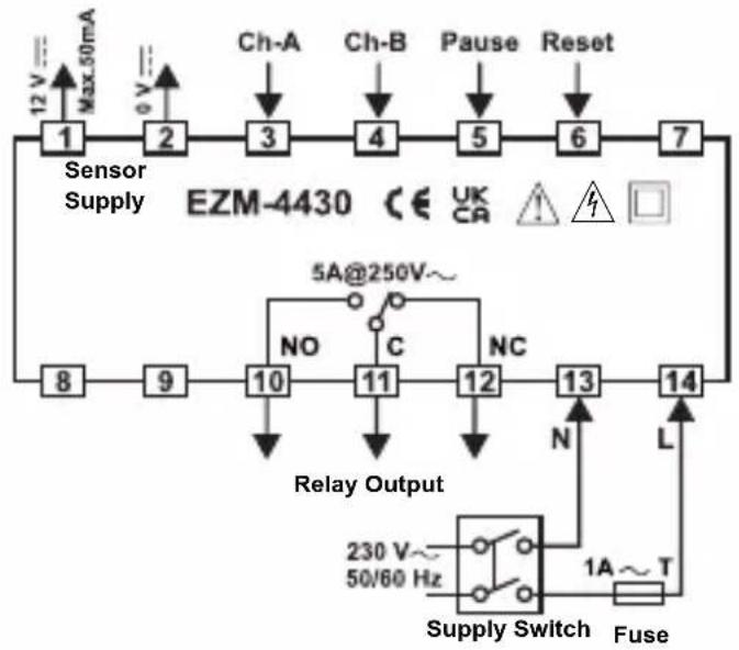
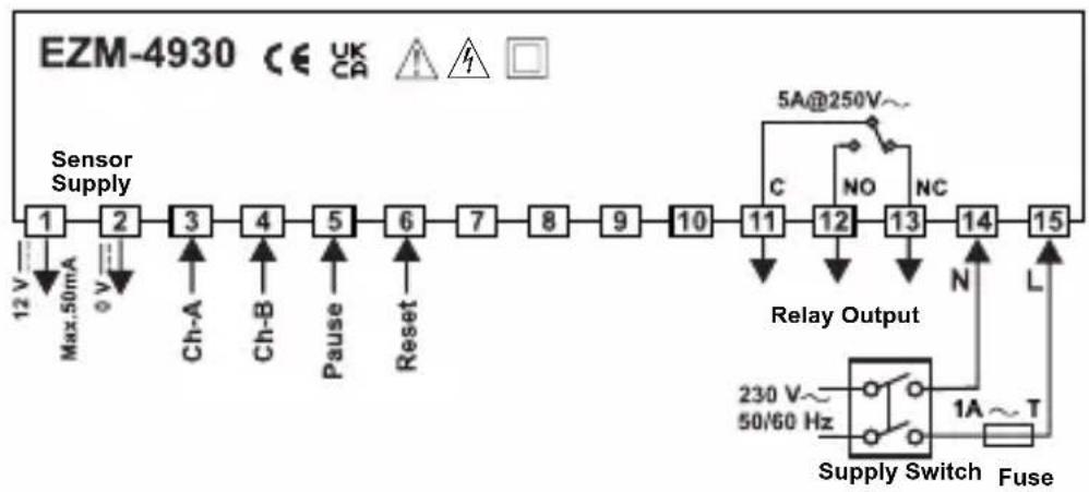
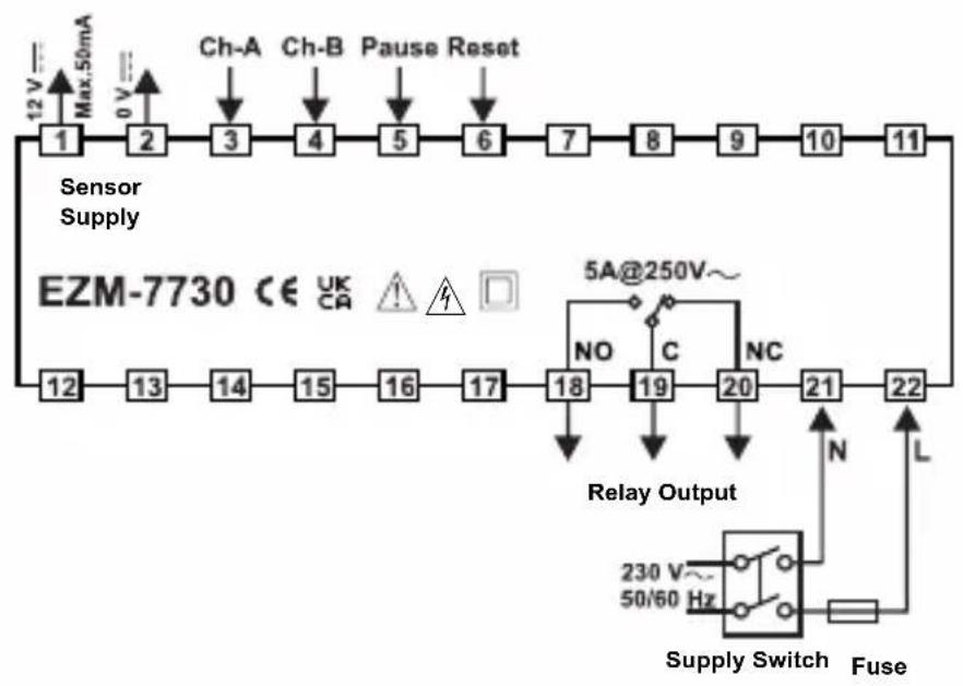
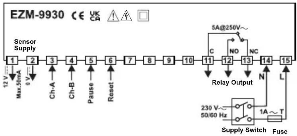
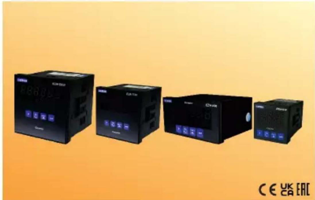
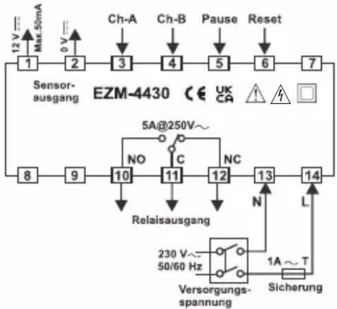
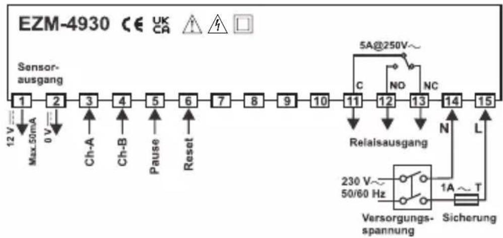
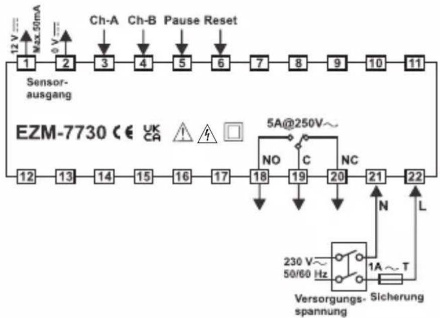
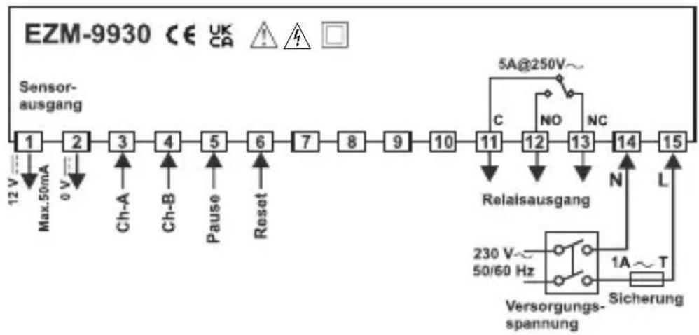
EZM-4430,EZM-4930,EZM-7730,EZM-9930 Programmable Counters
EZM-4430,EZM-4930,EZM-7730,EZM-9930
Programmable Counters
- 6 digits Process (PV) and 6 digits Set (SV) Value Display
- Operation with 1 Set Value
- Reset , Pause and ChA-ChB Counting Inputs
- NPN/PNP Type Operation
- Operation with Automatic and Manual Reset
- INC,DEC,INC/INC,INC/DEC,UP/DOWN, x1 / x2 / x4 Counting with
Phase Shifting Property - Multiplication Coefficient and Decimal Point Position
SPECIFICATIONS :
INPUTS :
Counting Inputs (Ch-A, Ch-B): Switch, Proximity, Capacitive sensor or encoder can be connected.
Reset Input: Switch, Proximity, Capacitive sensor or encoder can be connected.
Pause Input: Switch, Proximity, Capacitive sensor or encoder can be connected.
Sensor Type Selection: NPN or PNP can be selected.
Reset Function: Automatic or Manual.
Count Input Types and Maximum Frequency :
x1/x2/x4: Phase Shift (for encoder) Counting;Max.10 kHz.
Reset and Pause Input Filter : 2-50 msec (Can be adjusted in parameter.)
OUTPUT
Process Output : Relay Output (5A@250V~ at Resistive Load)
SUPPLY VOLTAGE
230V 50 / 60Hz(-15% ; + 10%) 3VA
Humidity non@oC#R#hensing),
Protection Class alp65nt.jpa20ear.
Weight:
EZM-4430 : 210 gr.
EZM-4930 : 240 gr.
EZM-7730 : 270 gr.
EZM-9930 : 340 gr.
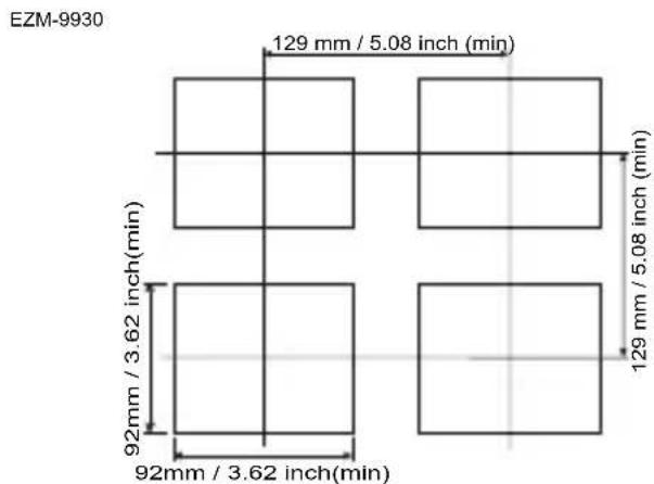
Dimensions:
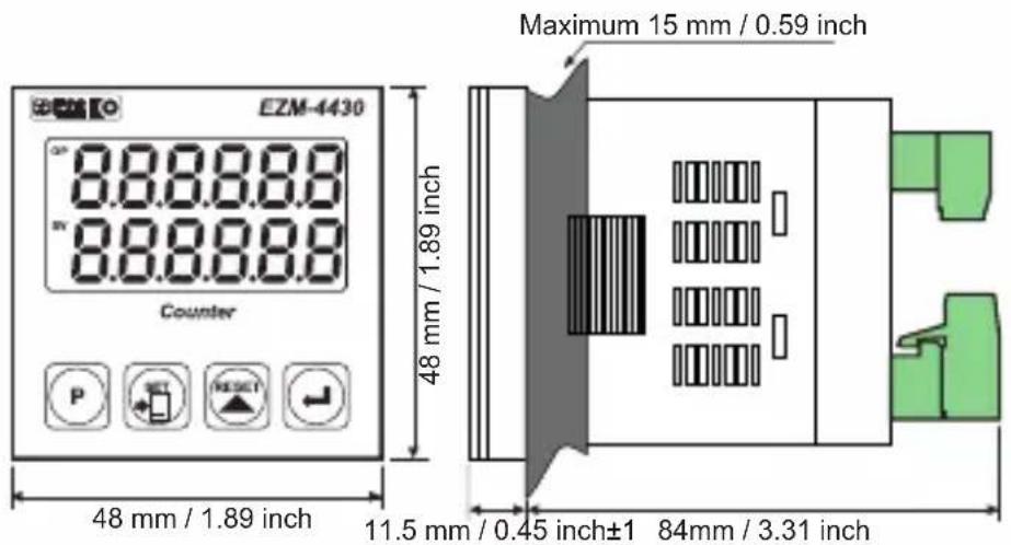
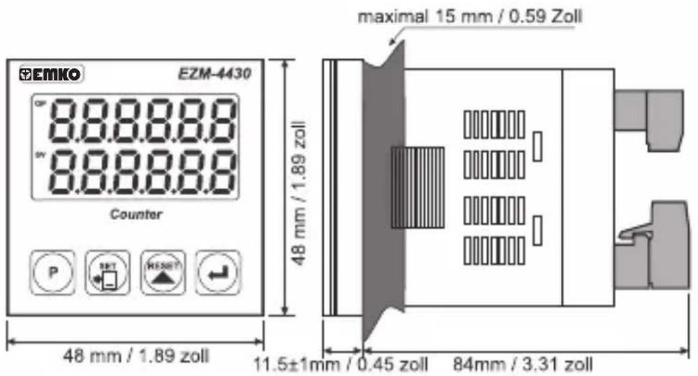
EZM-4430:(48×48mmDephmm)
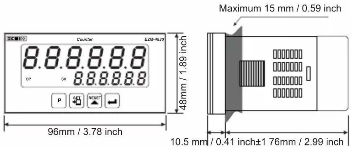
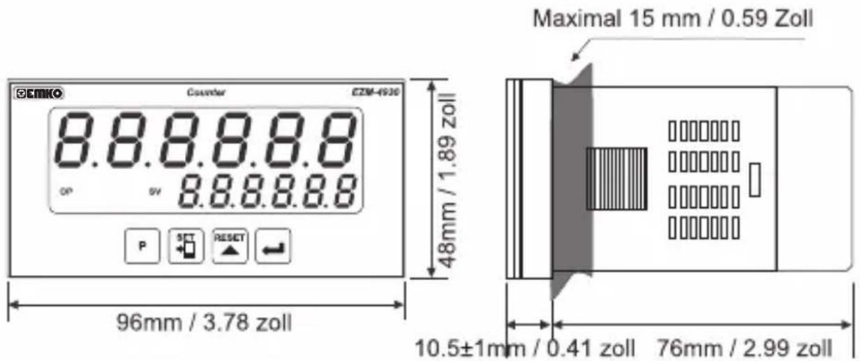
EZM-4930:(96x48mmDepthmm)
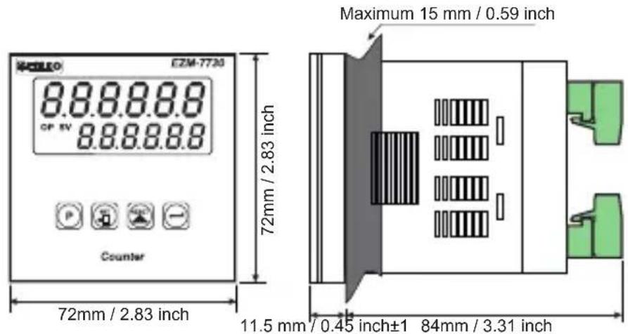
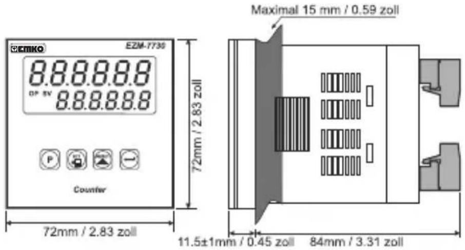
EZM-7730:(72x72mm,Dep55mm)
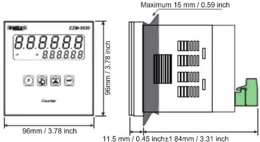
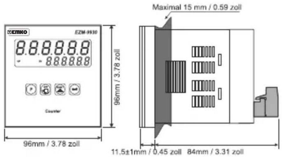
EZM-9930:(96x96mmDephmm)
Panel Cut-Out:
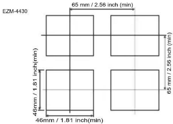
EZM-4430:(48x48mm)
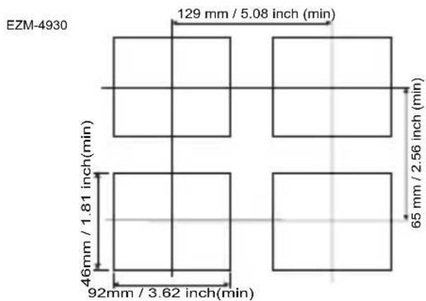
EZM-4930 : (96 x 48mm)
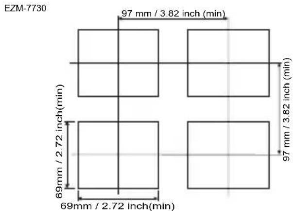
EZM-7730:(72x72mm)
EZM-9930:(96x96mm)
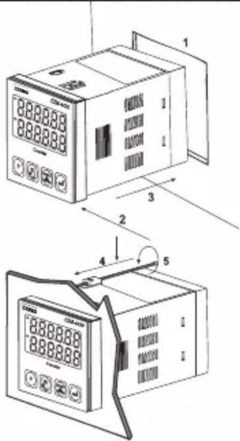
DIMENSIONS
PANEL MOUNTING
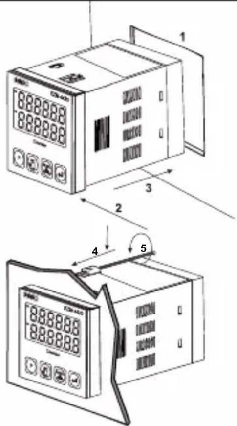
1- Before mounting the device in your panel, make sure that the panel cut-out is suitable.
2-Check front panel gasket Position.
3- Insert the device through the cut-out. If the mounting clamp are on the unit, put out them before inserting the unit to the panel.
4- Insert the unit in the panel cut-out from the front side.
5- Insert the mounting clamps to the holes that located top and bottom sides of device and screw up the fixing screws until the unit completely immobile within the panel.
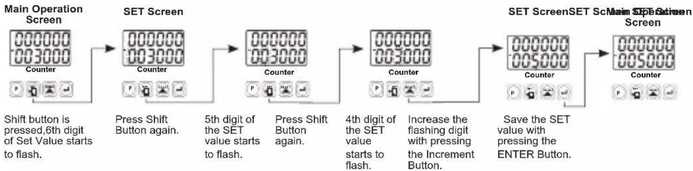
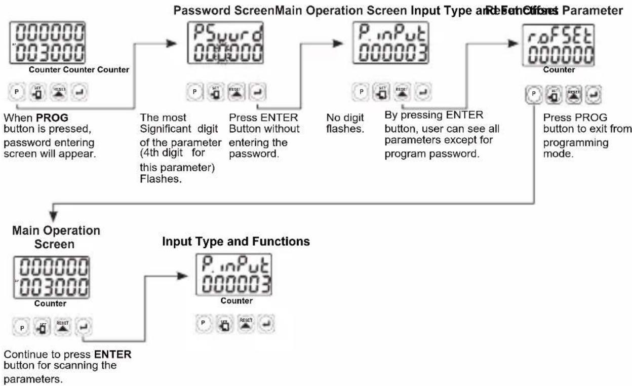
Accessing and Changing the Set Values
Accessing to the Program Parameters
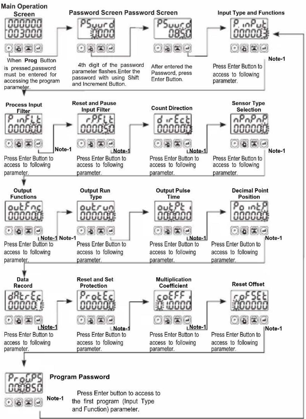
Note 1- Parameter value can be changed with Increment button. When the Enter button is pressed, parameter value will be saved and following parameter is accessed.
Note 2- Press "P" button is exit without saving the parameter value. Thus Main Operation Screen is appeared.
Parameter Definitions
P.inPut:Input Type and Functions (Default=3)
0: Up to 100 gunt on rising edge of Ch-A input.
1:Downward rising edge of Ch-A input.
2 Upcount on rising edge of Ch-A input count on rising edge of Ch-B input.(INC/DEC)
3: Upcount on rising edge of Ch-A input, Upcount on rising edge of Ch-B input (INC/INC)
4: Up/down on rising edge of Ch-A input when Ch-B is at 0 count on rising edge of Ch-A when Ch-B is at 1. (UP/DOWN)
5:x1P(fosenShetiregitalEncoder)
6:x2P(fosenShftingntalEncoder)
7:x4PfessnSreHemntalEncoder)
PnFLk: (Default=0)Filter time for Ch-A and Ch-B Inputs
It is used to protect against the electrical contact debounce or the signal that is less than the determined pulse time.
It can be adjusted from 000000 to 000050 milisecond.
: (Default=50)Filter time for Reset and Pause Inputs
It is used to protect against the electrical contact debounce or the signal that is less than the determined pulse time.
It can be adjusted from 00000 to 000050 milisecond.
:Count Direction (Default=0)
Upcount. (0-->Preset)
Downcount. ( Preset->0 )
_nP_nP :Sensor Type Selection (Default=0)
NPN Sensor type is selected.
PNP Sensor type is selected.
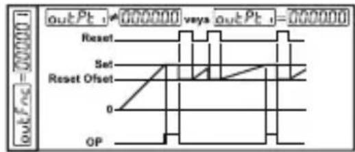
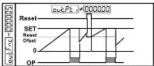
outFnc:Output Functions (Default=0)
0:Manuel Reset-1: Process counts, until manuel reset happens.When count value reaches the Set value, Output Position is changed.
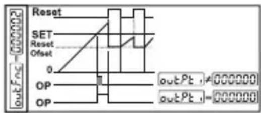
1:Manuel Reset-2: Process counts, until manuel reset happens.When count value reaches the Set value, Output Position is changed. Counting doesn't change continue over Set value.Output Position doesn't change, until manuel reset happens.
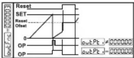
2:Manuel Reset-3: Process counts, until manuel reset happens.When count value reaches the Set value, Output Position is changed. After the end of the Output Pulse Time output positions changes the old position.
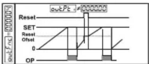
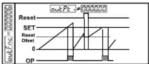
3:Automatic Reset-1:When count value reaches the Set value,Output position is changed.Process value automatically and counting will continue from "0"(up count) or "Set"(downcount).After the end of the Output Pulse Time output positions changes the old position.
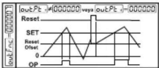
4: Automatic Reset-2: When count value reaches the Set value, Output position is changed. Counting doesn't continue over the Set value. Process value is reset automatically, counting continue from "0" (upcount) or "Set" (downcount) and Output position changes the old position at the end of the output pulse time.
5: Automatic Reset-3: When count value reaches the Set value, Output position is changed. Count value becomes zero. (For 0->P) Counting restarts on "0" value, but Set Value is shown on the Process value screen. Output position becomes the old and the Real count value can be seen at the end of output pulse time.
6: Automatic Reset-4: When count value reaches the Set value, Output position is changed.Count value is automatically reset and counting will continue (for 0->P ) and Output position changes the old position at the end of the output pulse time.
7:Automatic Reset-5:Process counts,until manuel reset happens.Output pulse time does not take into considera tion.This function can be preferred on systems that, upcounts or downcounts at the same time.
outrun:Output Run Type(Default=0)
00000 Normally De-energised.
00001 Normally Energised.
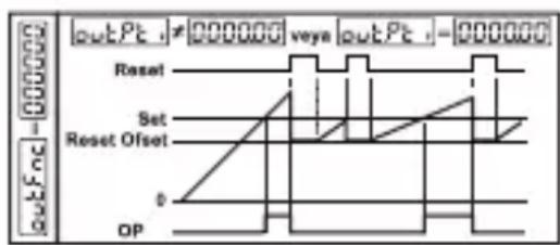
:Output Pulse Time (Default=0.00)
It determines how long Output will be active. It can be adjusted from 00.00 to 99.99 seconds. If it is 00.00 second, then it operates indefinitely.
Point: Point Position (Default=0)
No point.
Between first and second digits.
Between second and third digits. 00000
Between third and fourth digits.
Between fourth and fifth digits.
dRtEc: Data Record (Default=1)
Count value is saved to memory when power is disconnected and restored on power up.
Count value is not saved to memory when power is disconnected.
ProtEc:Reset and Set Protection (Default=0)
No Reset and Set protection.
0000 Only Reset button protection is active.
00002 Only Set button protection is active .
00003 Full Protection Reset and Set button protection is active.
coEFF : Multiplication Coefficient (Default=01.0000)
The Count value that is read from Process input, is multiplied with this value. Parameter value can be adjusted from 00.0000 to 99.9999. If this parameter is adjusted to "01.0000" then this parameter has no effect on Process input count, so Process value equal to the Process input count.
rofSet:Reset Offset(Default=0)
It can be adjusted from 000000 to 500000. When Process is manually reset, count process starts from this value.
ProGPS:ProgramPassword(Default=0)
It is used for accessing to the program parameters.
It can be adjusted from 00000 to 00999.
If it is 000000 ; there is no password protection while entering to the program parameters.
If operator accesses to the program parameters by entering "0" to PSword, then the operator can only see the parameter without changing, except ProGPS
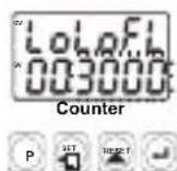
Failure Messages in EZM-XX30 Programmable Counter
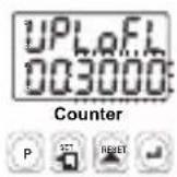
1- If Actual Value is flashing and counting is stopped; It appears if any of the count value is bigger than the maximum count value. To remove this warning and reset the count value press RESET button.
2- If Actual Value is flashing and counting is stopped; It appears if any of the count value is lower than the minimum count value. To remove this warning and reset the count value press RESET button.
Installation

Before beginning installation of this product, please read the instruction manual and warnings below carefully.
In package ,
-One piece unit
-Two pieces mounting clamp
-One piece instruction manual
A visual inspection of this product for possible damage occurred during shipment is recommended before installation.
It is your responsibility to ensure that qualified mechanical and electrical technicians install this product.
If there is danger of serious accident resulting from a failure or defect in this unit, power off the system and the electrical connection of the device from the system.
The unit is normally supplied without a power switch or a fuse. Use power switch and fuse as required.
Be sure to use the rated power supply voltage to protect the unit against damage and to prevent failure.
Keep the power off until all of the wiring is completed so that electric shock and trouble with the unit can be prevented.
Never attempt to disassemble, modify or repair this unit. Tampering with the unit may results in malfunction, electric shock or fire.
Do not use the unit in combustible or explosive gaseous atmospheres. During the equipment is putted in hole on the metal panel while mechanical installation some metal burrs can cause injury on hands, you must be careful.
Montage of the product on a system must be done with it's mounting clamp. Do not do the montage of the device with in appropriate mounting clamp. Be sure that device will not fall while doing the montage.
It is your responsibility if this equipment is used in a manner not specified in this instruction manual.
Warranty
EMKO Elektronik warrants that the equipment delivered is free from defects in material and workmanship. This warranty is provided for a period of two years. The warranty period starts from the delivery date. This warranty is in force if duty and responsibilities which are determined in warranty document and instruction manual performs by the customer completely.
Maintenance
Repairs should only be performed by trained and specialized personnel. Cut power to the device before accessing internal parts.
Do not clean the case with hydrocarbon-based solvents (Petrol, Trichlorethylene etc.). Use of these solvents can reduce the mechanical reliability of the device. Use a cloth dampened in ethyl alcohol or water to clean the external plastic case.
Other Informations
Manufacturer Information:
Emko Elektronik Sanayi ve Ticaret A.S.
Bursa Organize Sanayi Bolgesi, (Fethiye OSB Mah.) Ali Osman Sonmez Bulvari, 2. Sokak, No:3 16215 BURSA - TÜRKİYE
Phone : +90 224 261 1900 Fax : +90 224 261 1912
Repair and maintenance service information:
Emko Elektronik Sanayi ve Ticaret A.S.
Bursa Organize Sanayi Bolgesi, (Fethiye OSB Mah.) Ali Osman Sonmez Bulvarı, 2. Sokak, No:3 16215 BURSA - TÜRKİYE
Phone : +90 224 261 1900 Fax : +90 224 261 1912
Order Information
EZM-4430 (48x48 1/16 DIN)
EZM-4930 (96x48 1/8 DIN)
EZM-7730 (72x72 DIN)
EZM-9930 (96x96 1/4 DIN)
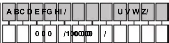
Supply VoltageA
2 24 V--- (-%15;+%15) / 24 V ~ (-%15;+%15) 50/60Hz
3 24V (-% 15; + % 10)50 / 60Hz
4 115V (-% 15; + % 10)50 / 60Hz
5 230V~(-%15;+%10) 50/60Hz
9 Customer (Maximum 240V (%15; +%10)) 50/60Hz
Output-1E
1 Relay Output (5A @ 250 V ~ at resistive load)
All order information of EZM-XX30 series are given on the table at above. User may form appropriate device configuration from information and codes that at the table and convert it to the ordering codes. Firstly, supply voltage then other specifications must be determined.
Please fill the order code blanks according to your needs.
Please contact us, if your needs are out of the standards.

Symbol Means Vac \~
Symbol Means Vdc
Symbol Means Vac and Vdc

Thank you very much for your preference to use Emko Elektronik products, please visit our web page to download detailed user manual.
www.emkoelektronik.com.tr
EZM-4430,EZM-4930,EZM-7730,EZM-9930 Programmierbare Zähler
EZM-7730: (72x72mm, Tiefe:95.5 mm)
EZM-9930: (96x96mm, Tiefe: 96mm)
Fronttafel:
EZM-4430: (48× 48mm)
EZM-4930: (96× 48mm)
EZM-7730: (72× 72mm)
EZM-9930: (96 x 96 mm)
ABMESSAGENGEN
SCHALTTFELMONTAGE
TENSION D'ALIMENTATION
230V 50 / 60Hz(-15% ; + 10%)3VA
115 V~(-15%;+10%) 3 VA
24V 50 / 60Hz (-15% ; + 10%) 3 VA
24 V\~(-%15;+%15) 4 VA/4W
Symbole designant Vcc
Symbole designant VacetVcc ≈

EMKO