— Motorcycle — Mode d'emploi PDF")
TY 125 (2024) - Motorcycle Sherco - Free user manual and instructions
Find the device manual for free TY 125 (2024) Sherco in PDF.

| Product type | Trial motorcycle |
| Brand | Sherco |
| Model | TY 125 (2024) |
| Overall length | 2 025 mm |
| Overall width | 810 mm |
| Seat height | 700 mm |
| Wheelbase | 1 308 mm |
| Ground clearance | 320 mm |
| Dry weight | 78 kg |
| Engine | 4-stroke SOHC, 123.7 cm³, air-cooled |
| Fuel system | Carburetor Ø 20 mm |
| Fuel | Unleaded 95 octane gasoline, 2.6 L tank + 0.5 L reserve |
| Transmission | 5-speed gearbox, multi-disc oil bath clutch |
| Front brake | Floating hydraulic disc 182 mm, Braktec 4-piston caliper |
| Rear brake | Hydraulic disc 150 mm, Braktec dual-piston caliper |
| Front suspension | Hydraulic telescopic fork Ø 40 mm, travel 177 mm |
| Rear suspension | Adjustable progressive shock absorber, travel 165 mm |
| Rims | Lightweight anodized alloy MORAD, 1.60"x21" (front), 2.15"x19" (rear) |
| Tires | Trial tubetype, tubeless |
| Ignition | Electronic CDI, 12V battery |
| Lighting | Headlight 12V 35/35W, turn signals 12V R10W, LED brake light |
| Maintenance | Engine oil change every 1000 km, clean air filter every 6000 km |
| Safety | Front and rear hydraulic brakes, side stand with spring |
Frequently Asked Questions - TY 125 (2024) Sherco
User questions about TY 125 (2024) Sherco
0 question about this device. Answer the ones you know or ask your own.
Ask a new question about this device
Download the instructions for your Motorcycle in PDF format for free! Find your manual TY 125 (2024) - Sherco and take your electronic device back in hand. On this page are published all the documents necessary for the use of your device. TY 125 (2024) by Sherco.
USER MANUAL TY 125 (2024) Sherco
MANUEL DU PROPRIÉTAIRE I OWNER'S MANUAL I MANUAL DE PROPietARIO I HALTER-HANDBUCH
INDEX
SHERCO
FRANÇAIS
P.1
ENGLISH
P.35
ESPANOL
P.69
DEUTSCH
P.103
SHERCO
Maintenance processes. 14
II offre 3 positions:
Maintenance processes
Maintenance processes

Maintenance processes
Maintenance processes
Maintenance processes
Maintenance processes
Maintenance processes
État des ressorts
Maintenance processes
Maintenance processes
Bougie sale: carburation excessive.
Bougie sale: carburation excessive.
Maintenance processes

AVERTISSEMENT
We want to thank you for the trust that you have placed in us by purchasing this product.
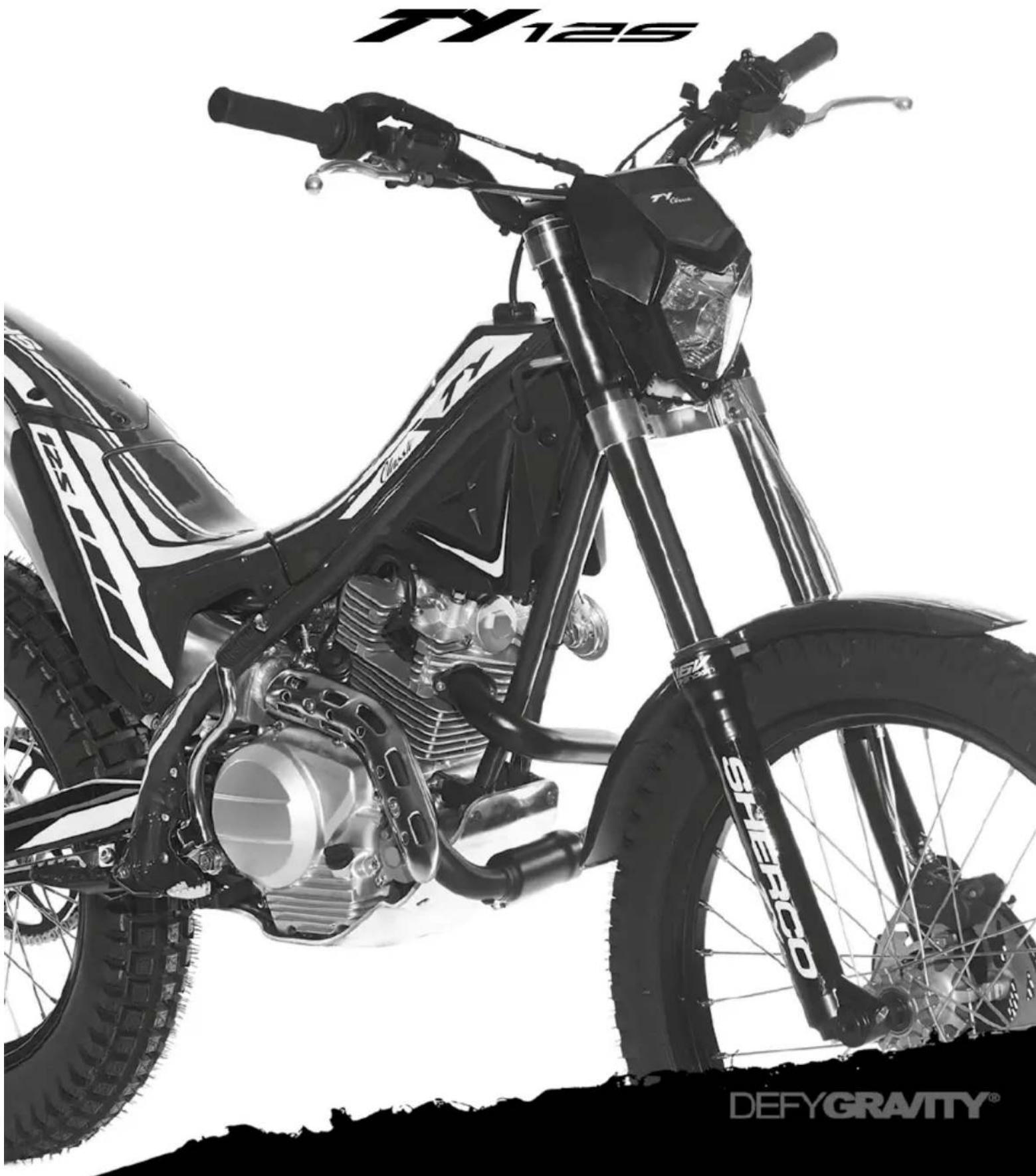
■ You are now the owner of a SHERCO TY 125 4T. All the pleasures of driving are promised to you if you follow the advice and instructions that SHERCO has set in this manual, and ride it in compliance with the applicable traffic laws.
This manual explains the operation, inspection, basic maintenance and focus of your SHERCO. If you have any questions about this manual or your machine, you should contact your SHERCO dealer: www.sherco.com / under «Dealers».
■ Be sure to carefully read this manual in its entirety before using your machine.
To keep your SHERCO in perfect condition for many years, perform all of the care and maintenance described in the manual.
(The vehicle you purchased may differ slightly from the vehicle presented in this manual.)
SHERCO reserves the right to make changes without providing notice.
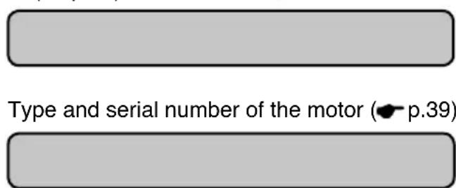
Serial number registration
Save the serial numbers of the vehicle in a safe location
Dealer stamp Frame number ( p.39)

SOMMAIRE
Technical details 38
Serial number location 39
Chassis identification number 39
Engine identification number 39
Control devices and controls 40
Clutch lever 40
Front brake lever 40
Rear brake pedal 40
Gear-change lever 40
Mechanical kick-start lever. 41
Ignition switch. 41
Display. 41
Lights, indicators and horn switches. 41
Electric star button 42
Choke lever 42
The fuel tank tap. 42
Prop-stand 43
Instructions for the first start-up 43
Riding instructions 44
Running the engine in 44
Starting the engine from cold 44
Starting the engine when warm 44
Gear change 45
Braking. 45
Parking. 45
Filling the tank with fuel 46
Maintenance chart. 47
Maintenance processes. 48
Position of the front brake lever. 48
Position of the clutch lever 49
Changing the headlight bulb 49
Changing the turn indicator bulb. 50
Changing the brake light 51
Changing the fuse 51
Battery 53
Checking and topping up the front brake fluid. 54
Bleeding the front brake fluid 54
Checking and topping up the rear brake fluid. 55
Bleeding the rear brake fluid. 55
Adjusting the pressure of the front brake action 56
Adjusting the tension of the clutch cable. 56
Adjusting the position of the rear brake pedal 56
Adjusting the throttle cable. 57
Adjusting the shock absorber 58
Condition of the brake discs. 58
Condition of the brake pads 59
Condition of the tyres 59
Condition of the chain tensioner 59
Condition of the springs. 60
Removing and reinstalling front wheel 61
Removing and refitting the rear wheel 62
Adjusting the chain tension. 63
Adjusting the carburettor 64
Condition of the spark plug. 65
Checking the air filter and its cleanliness 65
Checking and topping up the engine oil. 66
Draining engine oil 67
Technical details
DIMENSIONS
| Overall length | 2.025 mm |
| Overall width 810 mm | |
| Seat height 700 mm | |
| Wheelbase 1.308 mm | |
| Ground clearance 320 mm | |
| Dry weight 78 kg |
ENGINE
| Engine | 4 stroke SOHC Motor Euro4 |
| Displacement | 123,7 |
| Bore x Stroke 54 x 54 mm | |
| Cylinder lubrication Unleaded petrol, Nickasil coated cylinder treatment | |
| Fuel system Carburettor Ø 20 mm | |
| Cooling | Air cooled |
| Starting | Geared system with foldable kick-start lever/electric starter |
| Transmission | 5 speed sequential gearbox |
| Clutch | Multidisc in oil bath |
| Ignition Electronic CDI | |
CHASSIS
| Chassis | Single down-tube |
| Exhaust | Steel + Aluminium |
| Fuel tank 2.8 litre plastic fuel tank | |
| Skid plate Ergal (7075), with T6 treatment | |
| Front suspension Hydraulic telescopic 40 mm diameter with 177 mm of stroke. | |
| Rear suspension Rear shock, adjustable for compression and spring pre-load with 165mm of stroke. | |
| Front brake Disc Ø 182 mm, Braktec 4 pistons caliper | |
| Rear brake Disc Ø 150 mm, Braktec 2 pistons caliper | |
| Rims MORAD Anodised titanium light alloy rims, 1.60” x 21” and 2.15” x 19. | |
| Tyres | Tube type Trial front tyre and tubeless Trial rear tyre |
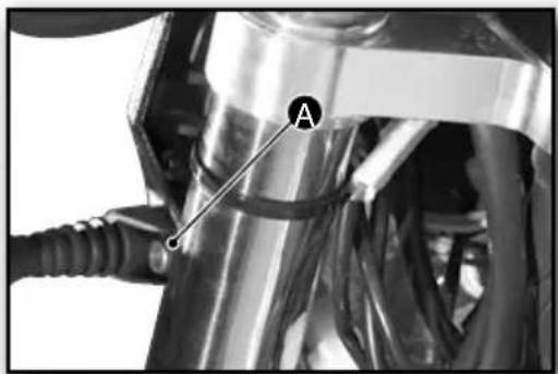
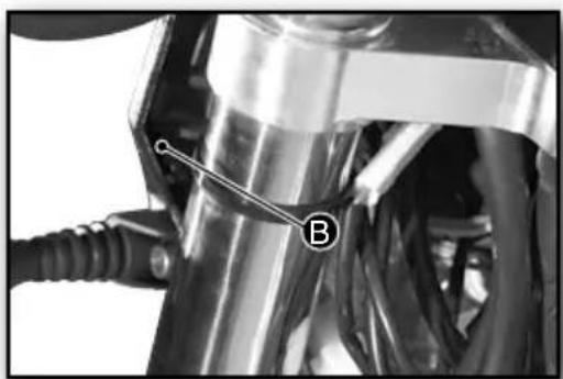
Serial number location
Chassis identification number

The machine's identification number can be found on the left-hand side of the steering column.
It is advisable to make a note of the chassis number in the box on page 36.
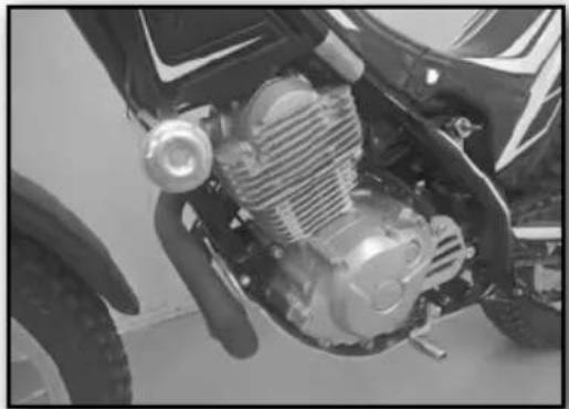
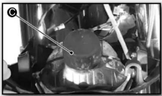
Engine identification number
The engine's identification number can be found on the right-hand side of the crankcase, next to the kick-start lever.
It is advisable to make a note of the engine number in the box on page 36.
Control devices and controls
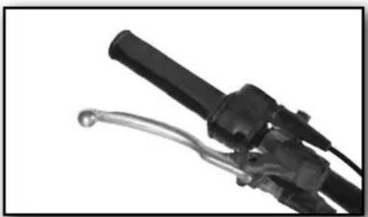
Clutch lever
The clutch lever is located on the left-hand side of the handlebars.
The tension of the clutch is adjusted using the screw (Maintenance Sect.).
The position of the clutch lever can be adjusted by varying the position of the lever-light switch assembly (Maintenance Sect.).
Front brake lever
The front brake lever is located on the right-hand side of the handlebars.
The tension of the brake cable is adjusted using the tensioning wheel (Maintenance Sect.).
The position of the brake lever can be adjusted by varying the position of the brake lever assembly (Maintenance Sect.).
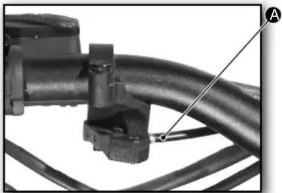
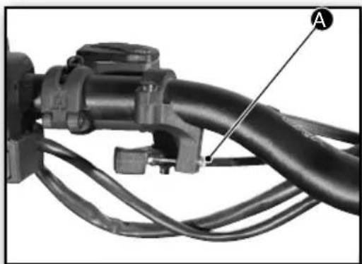
Rear brake pedal
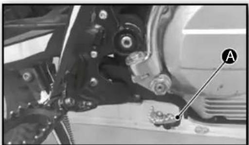
The rear brake pedal A is located in front of the right footrest.
The rear brake pedal is adjusted by varying the position of the threaded shaft (Maintenance Sect.).
Gear-change lever
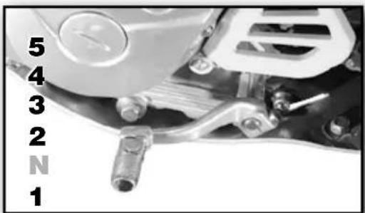
The gear-change lever is located in front of the left footrest.
The TY125 4-stroke gearbox consists of 5 gears and a neutral position.
To vary the position of the gear lever, see the Riding instructions Sect.
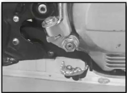
Mechanical kick-start lever
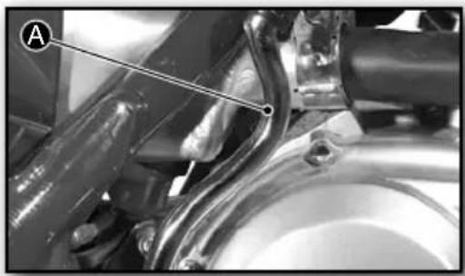
The mechanical kick-start lever A is located in front of the right footrest.
- Operate with a firm downward movement of the foot to start the engine.
- At the same time open the throttle by turning the twistgrip smoothly.
WARNING
Release the lever A when it reaches the end of its run and the engine starts.
Ignition switch
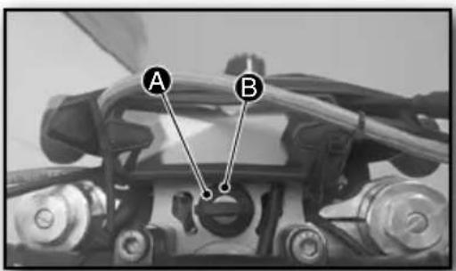
The ignition key is positioned to the right of the display.
It has 2 positions:
- Ignition off A
- Ignition and lights on B
Display
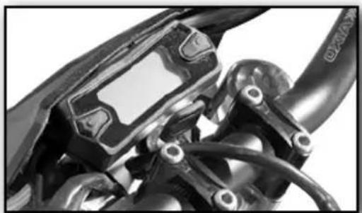
The display is situated in the centre of the handlebars.
Lights, indicators and horn switches
The switch is located on the left-hand side of the handlebars.
It consists of:
- DipswitchA
- Turn indicator switch 3.
- Horn button
Control devices and controls
Electric star button
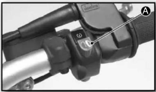
The switch is located on the right-hand side of the handlebars.
To start the motorcycle using the electric starter:
- Press the button A.
WARNING
There is no need to turn the throttle twist grip during starting. Release the button once the engine has started.
Choke lever
The choke lever is located on the right-hand side of the carburettor.
ON A: increases the richness of the mixture.
OFF B keeps the richness of the mixture at a suitable level.
Turning the choke on:
- Press the lever upwards and turn it inwards until it holds in position.
Turning the choke off:
- Press the lever downwards and turn it outwards until it releases.
The fuel tank tap
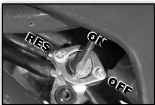
The fuel tap is located on the bottom left-hand side of the fuel tank.
It has 3 positions:
ON - Fully open, to allow fuel to flow through.
OFF - Access to fuel flow shut off.
RES - Access to the 0.5 litres of reserve fuel.
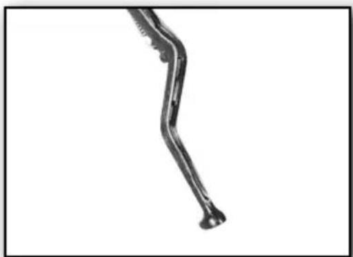
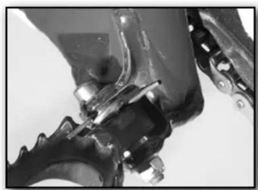
Prop-stand
The prop-stand is located behind the right-hand footrest.
It is fitted with a spring to aid in folding.
ATTENTION
During the folding operation it can be damaged.
The stand will fold by itself after passing the half way point.
WARNING
NEVER travel with the prop stand down.
Unfold the prop stand onto flat and firm surfaces.
Instructions for the first start-up
- Check that your SHERCO Dealer has provided you with all the documentation.
- Make sure you have read and understood the instructions set out in the user manual provided.
- Make a note of the chassis, engine and key numbers in this user manual (page 36).
- Adjust the control instruments as required.
- Check the quantity of fuel.
- Check that the tyres are in good condition (Condition of the tyres Sect.)
- Check that the drive chain is in good condition (Adjusting the chain tension Sect.)
- Check that the braking system is in good condition and working properly (discs, front brake lever and rear brake pedal).
- Check the condition of the clutch lever.
- Check that the headlight, turn indicators, sidelight and horn are working properly.
Riding instructions
Running the engine in
The TY125 4-stroke's engine has been constructed with an absolute precision so that the parts have correct tolerances and surfaces.
TIP
Nevertheless, SHERCO recommends running the engine gently, without forcing it, for the first 1,000 kilometres.
Starting the engine from cold
To start the engine from cold, perform the following steps:
- Switch on the ignition.
- Make sure the gear lever is in Neutral position (N).
- Turn on the choke A (Choke chapter).
- Turn the fuel tap to the ON position.
- Start the engine (either electrically or mechanically).
- Turn off the choke (after a maximum of 1km
WARNING
Avoid running with the choke ON.
After covering a distance of approximately 1 km, turn it OFF.
Starting the engine when warm
To start the engine when warm, perform the following steps:
- Switch on the ignition.
- Make sure the gear lever is in Neutral position (N).
- Check that the choke A is OFF (Choke chapter).
- Turn the fuel tap to the ON position.
- Start the engine.
Gear change
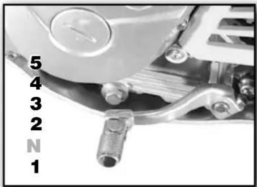
The TY125 4-stroke gearbox has 5 gears plus the neutral position.
To change the gears:
- Hold in the clutch lever.
- At the same time turn the throttle twist-grip towards you.
- Press down the gear lever to select 1st gear.
- Release the clutch lever smoothly.
- Put the front of your foot under the gear lever and lift it upwards to select 2nd gear and the remaining gears.
Neutral position (N) can be found between 1st and 2nd gears.
Braking
To use the brakes correctly, apply the front and rear brakes at the same time.
Use engine braking, without revving the engine, to aid in braking more quickly.
ATTENTION
Avoid sharp braking that will lock the wheels and may lead to falls.
Brake before not during bends.
■ Parking
- Apply the motorcycle brakes.
- Turn off the ignition using the ignition key.
- Shift the gear lever to 1st gear.
- Fold down the prop-stand onto a flat and firm surface.
ATTENTION
The exhaust pipe and silencer will be hot after running the bike so you should avoid contact with these items.
Avoid parking in places with a risk of fire, such as dry grass or flammable materials.
Riding instructions
Filling the tank with fuel
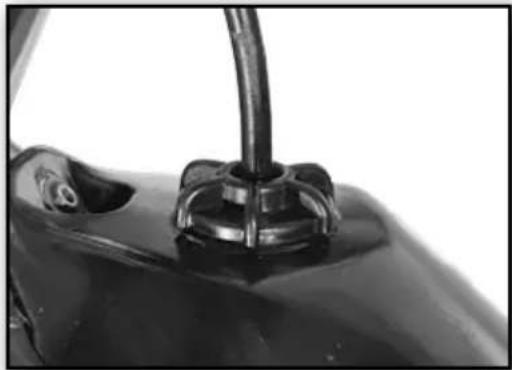
The fuel tank is designed to hold 2.6 litres plus 0.5 litres reserve.
Use 95 octane unleaded petrol.
To fill the tank, proceed as follows:
- Park the motorbike (see Parking section).
- Turn the fuel cap to the left to remove it.
- Fill the tank with 95 octane unleaded petrol.
- Refit the fuel cap by turning it to the right.
TIP
Withdraw the pipe at the front end to aid in turning the fuel cap.
WARNING
Turn off the engine before refuelling.
Remove any traces of fuel that may have spilled onto the engine, exhaust pipe and the surface of the tank.
Make sure the fuel cap is correctly closed before starting the engine.
ATTENTION
Petrol is highly flammable and toxic.
Avoid refuelling close to naked flames or lit cigarettes.
Maintenance chart
| OPERATION TO BE PERFORMED | distance in KMS | ||||||||
| every 1.000 | 6.000 | 12.000 | 18.000 | 24.000 | 30.000 | 36.000 | |||
| Idling | C | E | E | E | E | ||||
| Play in the throttle twist-grip | S-C-O-A | E | E | E | E | ||||
| Spark plug electrode gap | N-C-O-A | E | E | E | E | E | E | ||
| Air filter | N-C-O-A | E | O | E | O | O | |||
| Brake pad wear | C | E | E | E | E | E | E | ||
| Brake fluid level | C | E | E | E | E | E | E | E | |
| Brake fluid | S-O | 2 years | E | ||||||
| Front brake, rear brake | C | E | E | E | E | E | E | ||
| Clutch | A | E | E | E | E | E | E | E | |
| Clutch | CóO | O | E | O | |||||
| Engine oil | S-O | O | O | O | O | O | O | ||
| Engine oil filter | O | O | O | O | |||||
| Drive chain | L-O-A | 1.000 | |||||||
| Drive chain arrow | C-O-A | 1.000 | |||||||
| Tyre wear | C | E | E | E | E | E | E | ||
| Steering | S-O-A | E | E | E | E | E | E | E | |
| Tension of the spokes and warp of the wheel | S-O-A | E | E | E | E | E | E | E | |
| Tightness of the nuts, bolts and joints | C-O-AC | E | E | E | E | E | E | E | |
| General lubrication | S-C-O-A | E | E | E | E | E | E | E | |
| Front forks fluid | S-O | E | E | E | E | E | |||
| Swinging arm pivot | S-O-L-A | E | E | E | |||||
| Lubrication of the steering bearing | S-O-L-A | E | E | E | |||||
| Front brake cylinder | S-O | 2 years | E | ||||||
| Brake pedal cylinder | S-O | 2 years | E | ||||||
| Brake hoses | S-O-C | 2 years | E | E | |||||
| Fuel pipe | S-O-C | 2 years | E | E | |||||
| Valve play | S-A | 2 years | E | E | E | E | |||
| Oil filte | N | E | E | E | E | ||||
C = Control
A = Adjust
O = Renew
E = Operation to be performed
S = Consult a Sherco dealer
N = Clean
L = Lubricate
Maintenance processes
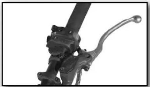
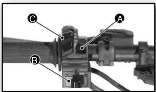
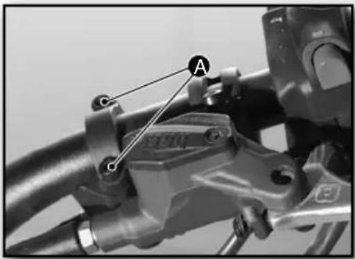
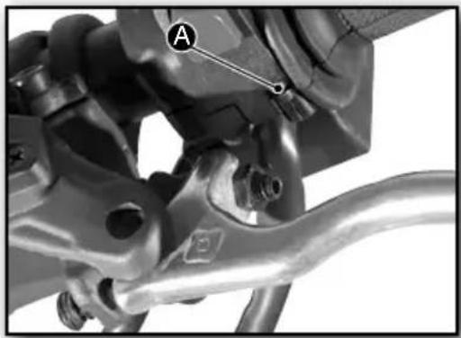
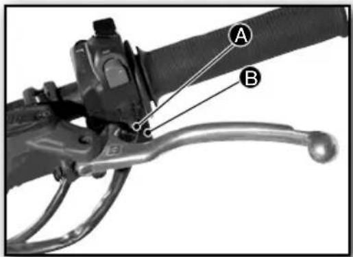
Position of the front brake lever
ATTENTION
The hand should be in a relaxed position and able to apply pressure on the lever.
In order to be able to pull on the lever properly during the braking operation, the position of the lever needs to be adapted to the physique of the rider.
To alter the position:
- Loosen the 2 screws An the lever-reservoir assembly A.
- Sit on the seat.
- Place your feet on the footrests.
- Place your hand on the lever and position it as desired.
- Secure the position by tightening the two screws A.
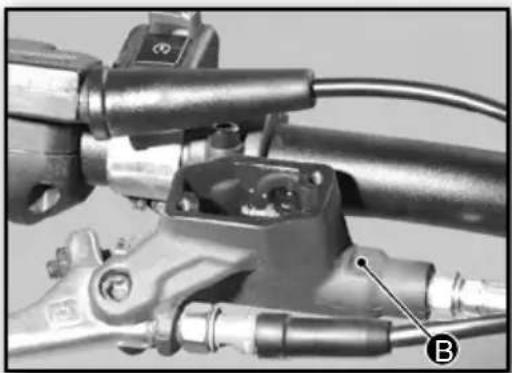
To change the distance between the lever and the throttle twist-grip:
- Screw or unscrew the threaded screw B.
Turn to the right for a SHORTER DISTANCE.
Turn to the left for a LONGER DISTANCE.
WARNING
After changing the position, check and adjust the play in the front brake.
Position of the clutch lever
ATTENTION
The hand should be in a relaxed position and able to apply pressure on the lever.
In order to be able to pull on the lever properly during the clutch release operation, it is essential that the position of the lever is adapted to the physique of the rider.
To alter the position:
- Loosen the 2 screws A on the lever-switch assembly.
- Sit on the seat.
- Place your feet on the footrests.
- Place your hand on the lever and position it as desired.
- Secure the position by tightening the two screws A.
WARNING
After changing the position, check and adjust the clutch cable.
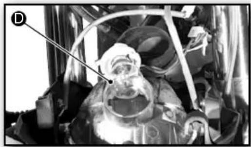
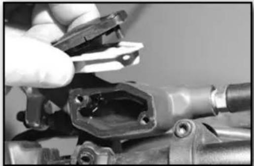
Changing the headlight bulb
ATTENTION
This operation should be performed with the ignition off.
Removal:
- Remove the central screw Alocated in the top centre.
- Remove the two headlight plate rubbers B.
- Tilt it forwards.
Maintenance processes
- Turn the bulb holder to the left.
- Press the bulb D in and turn it to the left.
- Pull the bulb out to remove it.
Type of bulb: 12v 35/35W
Refitting:
- To refit, proceed in reverse order to removal.
TIP
Deposit the "old" bulb where it can be recycled.
Changing the turn indicator bulb
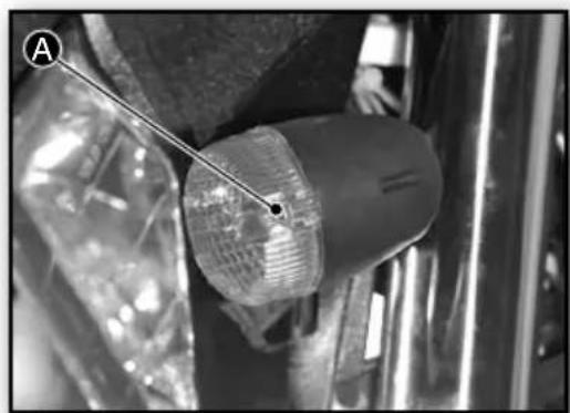
ATTENTION
This operation should be performed with the ignition off.
Removal:
- Remove the screw located at the rear.
- Press the bulb A in and turn it to the left.
- Pull the bulb out to remove it.
Bulb type: 12V R10W
Reassembly:
- Reverse the disassembly.
WARNING
When mainting, place the pens flauge correctly.
TIP
Put the used bulb in a suitable place for recycling.
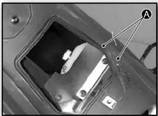
Changing the brake light
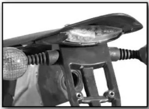
ATTENTION
This operation should be performed with the ignition off.
Removal:
- Remove the 3 screws and washers Afrom the rear mudguard.
- Disconnect the wiring terminal B.
- Remove the brake light.
Type: the brake light is a LED unit and the complete assembly needs to be renewed.
Refitting:
- To refit, proceed in reverse order to removal.
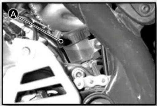
Changing the fuse
ATTENTION
This operation should be performed with the ignition off.
The fuse is situated below the fuel tank, and therefore the following have to be removed:
- The seat (Seat chapter).
Removal:
-
Remove the rear mudguard by removing the front screw A.
-
Remove the box-filter support together with the air filter box.
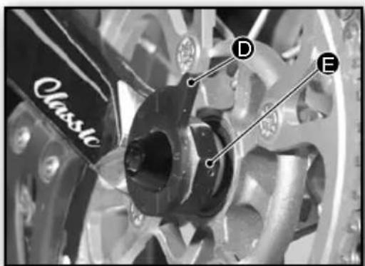
Maintenance processes

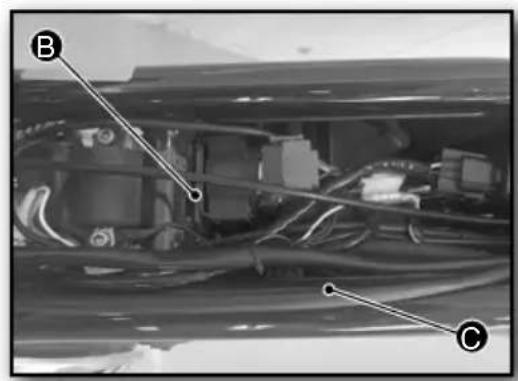
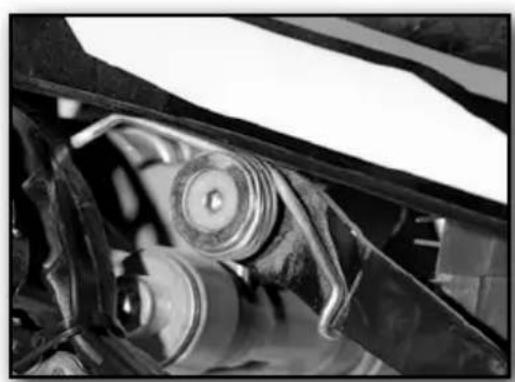
- Remove the shock absorber at the top
WARNING
Place an axle stand under the engine to prevent it from dropping down on removing the upper bolt from the shock absorber.
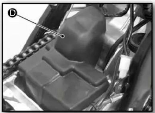
- Remove the protective rubber D.
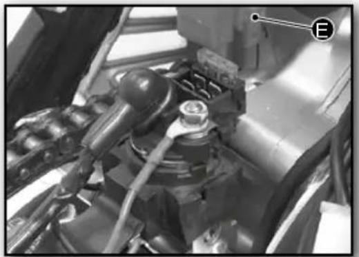
- Disconnect the wiring E.
Type of fuse: 20 Amp
Refitting:
- Proceed in reverse order to removal.
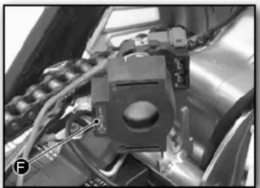
To access the spare fuse:
- Perform all the above operations.
- Remove the relay choke assembly.
The spare fuse Fs located at the bottom of the rubber.
Battery
The fuse is located under the filter box, and the following will therefore need to be removed:
- The seat (Seat Chapter).
Removal:
- Repeat the steps in the previous chapter until the protective rubber A is removed.
- Disconnect the wires:
POSITIVE (red)
NEGATIVE (black)
-Remove the retaining rubber.
Refitting:
- To refit, proceed in reverse order to removal.
WARNING
For the first connection or replacement of the battery, various display parameters need to be configured. (Maintenance Sect.).
TIP
Deposit the "old" battery where it can be recycled.
Maintenance processes
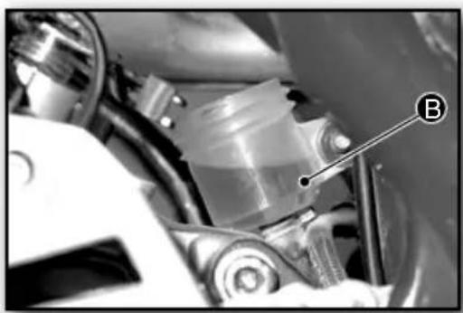
Checking and topping up the front brake fluid
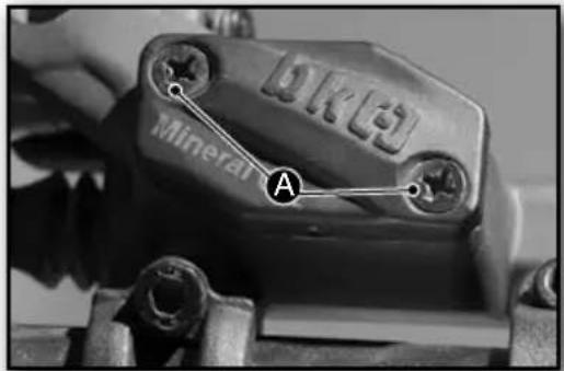
The front brake reservoir is located next to the brake lever. It is fitted with an inspection window for checking the fluid level.
WARNING
To inspect it correctly, make sure the motorcycle is in an upright position.
To top up the fluid:
- Remove the two screws Aom the reservoir cover.
- Remove the internal rubber.
- Top up the fluid.
Type of brake fluid: DOT4.
WARNING
The brake fluid level must be between 3 and 4mm from the top edge.
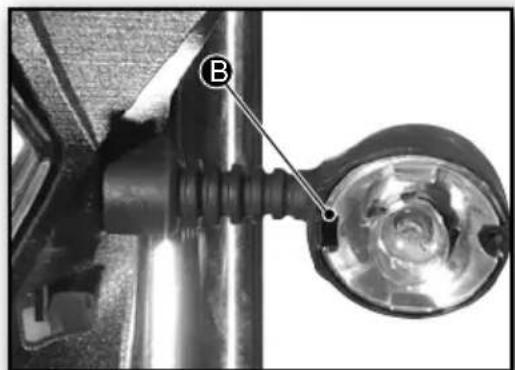
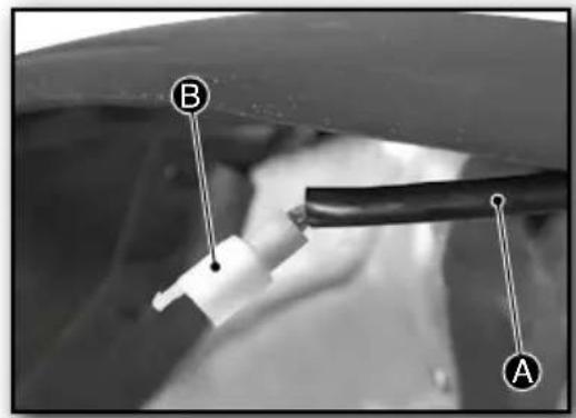
Bleeding the front brake fluid
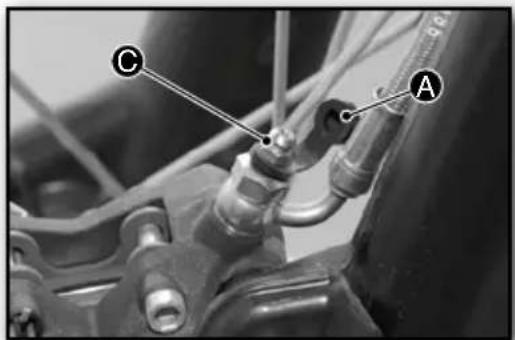
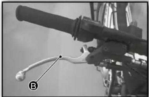
To bleed the front brake system:
- Remove the reservoir cover (see previous section).
- Remove the black protective cap A.
- Press in the front brake lever B and hold it in.
- Slightly loosen the protected device with the black bleeding nipple positioned next to the hose attachment.
- Repeat various times until the air has been eliminated from the circuit.
- Refit the black protective cap A.
- Refit the reservoir rubber and cover.
TIP
Place a cloth under the bleed nipple to absorb the fluid.
WARNING
Brake fluid is highly corrosive, therefore remove any spillage that may have come into contact with parts of the motorbike.
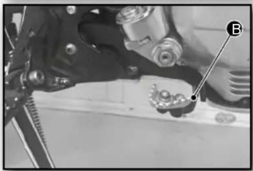
Checking and topping up the rear brake fluid
The rear brake fluid reservoir is located next to the kick-start lever.
WARNING
To inspect the fluid correctly, make sure the motorcycle is in an upright position.
To top up the fluid:
- Remove the threaded cap from the reservoir A
- Remove the internal rubber and the pressure ring.
- Top up the fluid.
Type of brake fluid: DOT4.
WARNING
The brake fluid level must be between the MIN and MAX marks B.
Bleeding the rear brake fluid
To bleed the rear brake system:
- Remove the reservoir cap (see previous section).
- Remove the black protective cap A.
- Press the rear brake pedal B and hold it down.
- Slightly loosen the protected device with the black bleed nipple positioned next to the hose attachment.
- Repeat various times until the air has been eliminated from the fluid circuit.
- Refit the black protective cap A.
- Refit the reservoir rubber and cap.
TIP
Place a cloth under the bleed nipple to absorb the fluid.
WARNING
Brake fluid is highly corrosive, therefore remove any spillage that may have come into contact with parts of the motorbike.
Maintenance processes
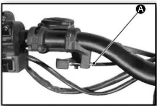
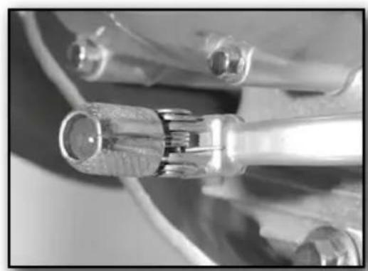
Adjusting the pressure of the front brake action
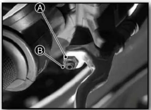
The tension of the front brake lever is adjusted using the threaded shaft
- Loosen the locking nut A.
- Screw the shaft in or out B.
- Lock the position with the nut A.
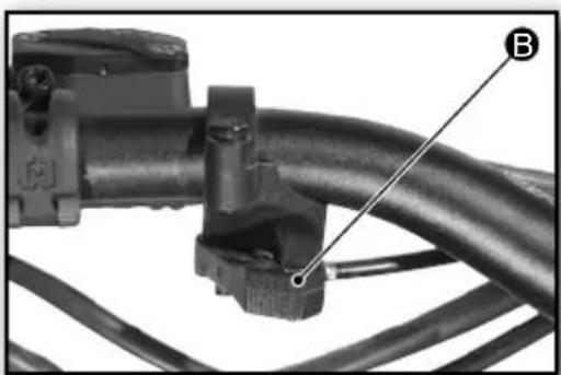
Adjusting the tension of the clutch cable
The tension of the clutch cable is adjusted using the threaded shaft B.
- Loosen the locking nut A.
- Screw the shaft in or out B.
- Lock the position with the nut A.
Adjusting the position of the rear brake pedal
The rear brake pedal is located in front of the right footrest.
The position of the rear brake pedal is adjusted by varying the position of the threaded shaft.
- Unscrew the locknut A.
- Screw the shaft in or out B.
- Lock the position by tightening the nut A.
Adjusting the throttle cable
The throttle cable play is factory set, although the user can also adjust it:
To access the throttle cable adjustment shaft, the seat will first have to be removed (Seat Sect.).
- Remove the fuel tank by pulling it backwards.
- Loosen the locking nut B.
- Screw the threaded shaft in or out
- Lock the position with the locknut B.
WARNING
After adjustment, start the engine and turn the handlebar to both sides to make sure there are no accelerations produced by the cable being too tight.
WARNING
The throttle cable should NEVER be under tension when closed.
The throttle twist grip should have a free play of 2 to 3mm
Maintenance processes
Adjusting the shock absorber
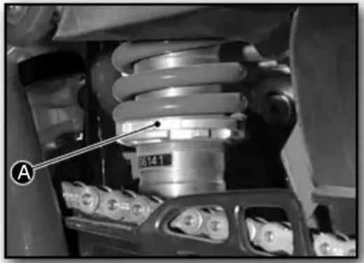
Spring compression:
The ring is used to adjust and set the position in order to change the preload on the spring.
- Toothed and threaded ring A.
Turn to the right for: MORE PRESSURE.
Turn to the left for: LESS PRESSURE.
Condition of the brake discs
The wear on the thickness of the discs is produced in the area of contact between the disc and the brake pads.
ATTENTION
Avoid riding the machine if the wearing area is not greater than 2.7mm
Condition of the brake pads
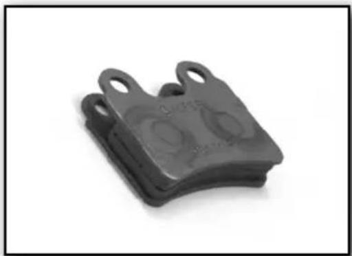
The wear on the thickness of the pads is produced in the area of contact between the disc and the brake pads.
WARNING
Riding the machine with a brake pad thickness of less than 1mm may damage the discs.
Condition of the tyres
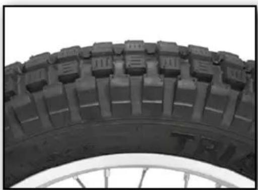
Much of the good performance of the motorcycle depends on the type, condition and correct pressure of the tyres.
Front tyre pressure: MAX. 0.8 - MIN. 0.4
Rear tyre pressure: MAX. 0.8 - MIN. 0.4
ATTENTION
Avoid riding the machine if the minimum tread is not greater than 2mm
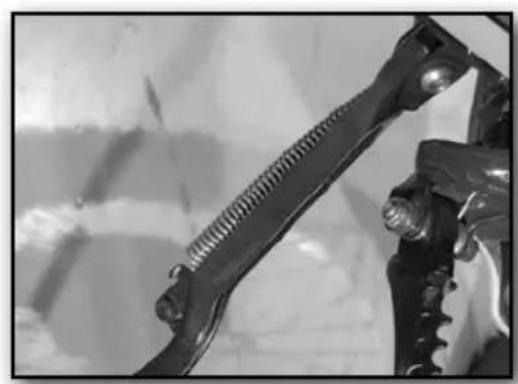
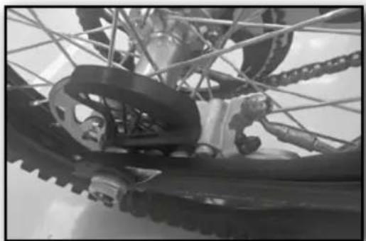
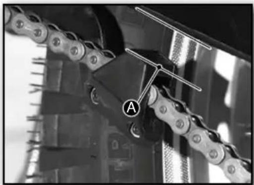
Condition of the chain tensioner
The chain tensioner is one of the elements that suffers most wear, especially the spring, which is responsible for maintaining the pressure on the chain.
WARNING
Keep the tensioner clean and well greased.
Maintenance processes
Condition of the springs
The gear-change lever and the footrests are retractable to prevent breakage in case of striking obstacles.
The gear-change lever comprises an anchor with a spring that allows 90 degrees of movement, thereby recovering its original position instantly.
The anchors on the gear-change lever and the footrests should be clean and lubricated to allow them to fold up properly as necessary and return to their position with the action of the spring.
The spring on the prop-stand and the chain tensioner should be equally clean to ensure perfect operation.
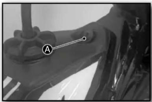
Removing and reinstalling front wheel
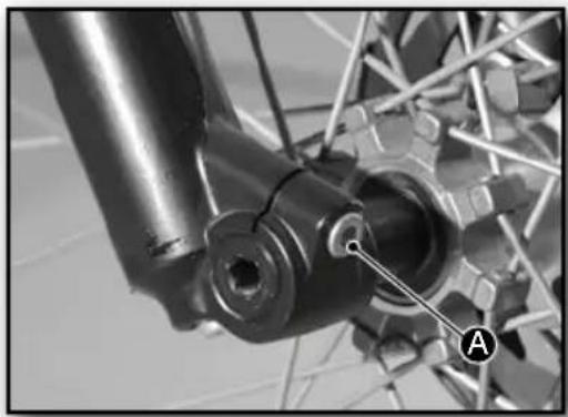
WARNING
Place the motorcycle in an upright position and immobilise it at the rear.
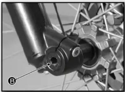
To remove the front wheel:
- Remove the bolt A from the right fork.
- Remove the wheel shaft ③.
To refit the front wheel:
- Proceed in reverse order to the removal.
TIP
During the process do not press the brake lever. If the lever has been pressed, the callipers will have to be pushed back to make them re-separate. If necessary, refill with brake fluid and bleed the corresponding circuit.
WARNING
Take care when inserting the wheel to ensure that the disc is not damaged by the brake pads. Once everything is fitted, check the correct brake operation before riding the machine.
Maintenance processes
Removing and refitting the rear wheel
WARNING
Place the motorcycle in an upright position and immobilise it at the front.
To remove the rear wheel:
- Remove the wheel shaft nut A.
- Remove the wheel shaft B.
TIP
Tap the end of the wheel shaft with a nylon mallet to aid removal.
- Push the wheel forwards.
- Remove the chain from the wheel sprocket.
- Withdraw the wheel backwards, releasing the rear disc brake from the calliper.
To refit the back wheel:
- Proceed in reverse order to the removal.
- Adjust the chain tension (Adjusting the chain tension chapter).
TIP
During the process do not press the brake pedal. If the pedal has been pressed, the callipers will have to be pushed back to make them re-separate. If necessary, refill with brake fluid and bleed the corresponding circuit.
WARNING
Take care when inserting the wheel to ensure that the disc is not damaged by the brake pads. Once everything is fitted, check the correct brake operation before riding the machine.
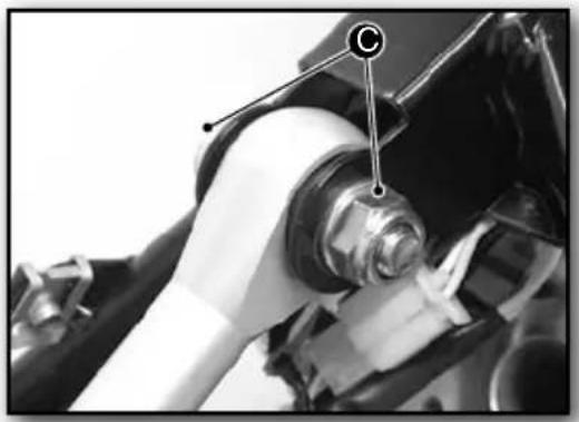
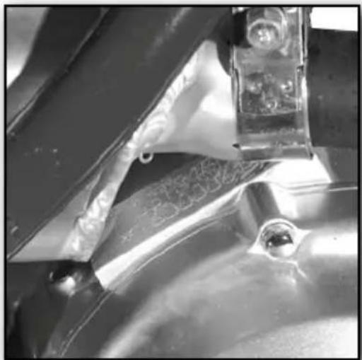
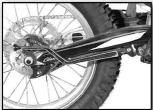
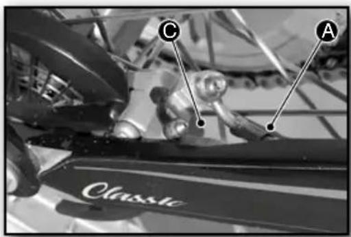
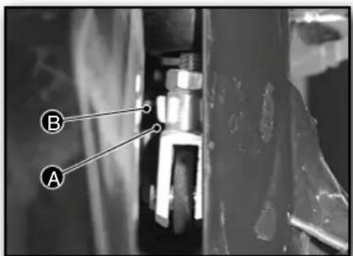
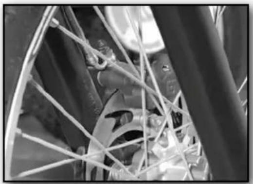
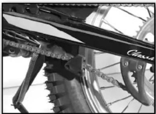
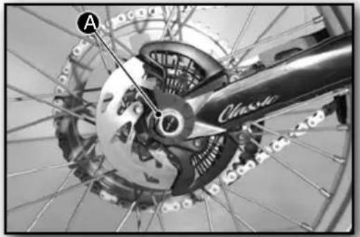
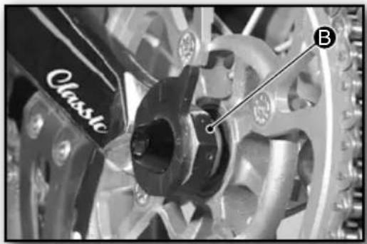
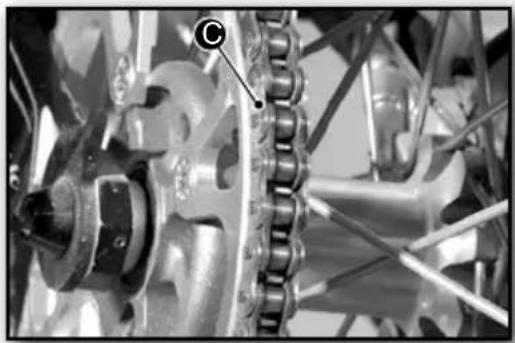
Adjusting the chain tension
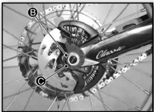
The chain must be given special attention because the life of the sprocket assembly, crown wheel and the chain itself depends on its good maintenance.
The area A for checking the chain tension is next to the tensioner, as shown in the image.
WARNING
The vertical play of the chain in the area where the tensioner acts should be between 10 and 15 mmA
To make the adjustment:
- Loosen the nut B and the wheel shaft Eom the wheel.
- Turn the 2 eccentric adjusters and symmetrically until the proper chain tension is obtained.
WARNING
Place the motorcycle in an upright position and immobilise it at the front.
WARNING
The position of the two eccentric adjusters should be symmetrical to ensure proper alignment between the wheel sprocket and the drive sprocket.
WARNING
Check the condition and tension of the chain tension and its greasing regularly. See Maintenance table.
Maintenance processes
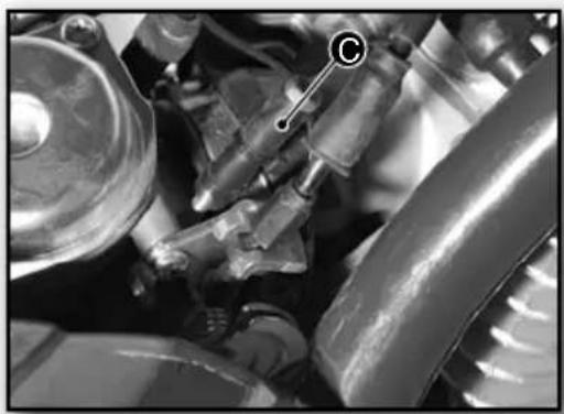
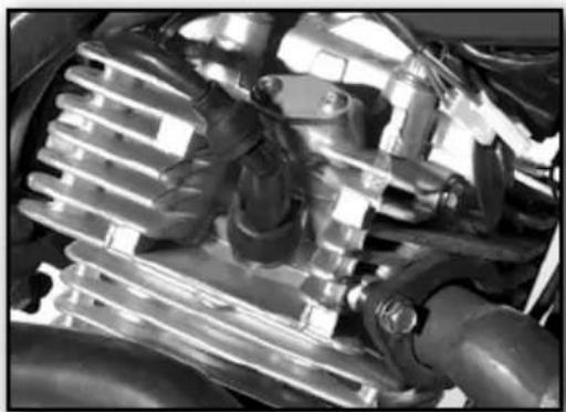
Adjusting the carburettor
The carburettor adjustment is factory set, however, depending on the altitude and weather conditions, it may require minor adjustments.
The idling speed and the richness of the (air-fuel) mixture can be adjusted.
A - IDLE: minimum engine carburetion.
- RICHNESS: air-fuel mixture.
The condition of the spark plug is useful for detecting the condition of the richness of the carburettor mixture.
Spark plug has dry deposits - poor carburetion.
Clean spark plug - correct carburetion.
The spark plug is dirty - excessive carburetion.
| ORIGINAL CARBURETTOR SETTINGS | |
| Type of carburettor | BS25-107 |
| Main jet | 130 |
| Idle jet | 17,5 |
| Carburettor needle | 4B01 |
| Needle position | 4 |
| Mixture adjusting screw open | 4,5 |
| ALTITUDE IDLE JET MAIN | JET | |
| From 0 to 700 meters | 17,5 | 130 |
| From 700 à 1400 meters | 17,5 | 122,5 |
| From 1400 à 2000 meters | 17,5 | 115 |
| From 2000 meters and more | 17,5 | 107,5 |
Condition of the spark plug
A spark plug that is in good condition allows the engine to run properly.
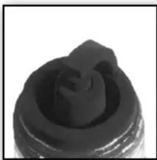
The condition of the spark plug will reveal whether the engine combustion is correct:
Spark plug has dry deposits - poor carburetion.
Clean spark plug - correct carburetion.
The spark plug is dirty - excessive carburetion.
Type of spark plug: NGK CR6HSA
WARNING
Check the condition of the electrode and the spark regularly. See Maintenance table.
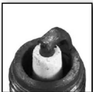
Spark plug has dry deposits
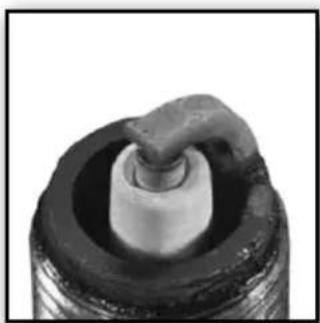
Clean spark plug Dirty spark plug
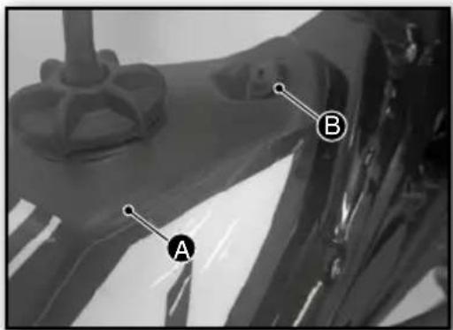
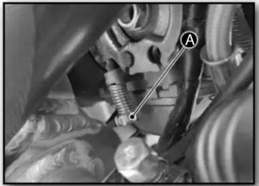
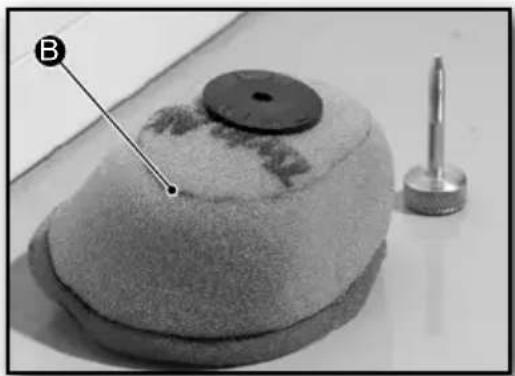
Checking the air filter and its cleanliness
To access the air filter, the seat will first have to be removed (Seat Sect.).
Removal:
- Remove the rear mudguard.
- Withdraw the spring backwards A.
- Remove the air filter B.
Refitting:
- Proceed in reverse order to the removal.
Maintenance processes
WARNING
If the machine is ridden on dirt roads, the times scheduled on the maintenance table for changing the filter must be reduced.
The air filter should be lightly smeared with oil.
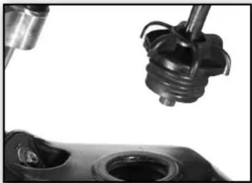
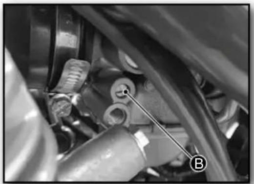
Checking and topping up the engine oil
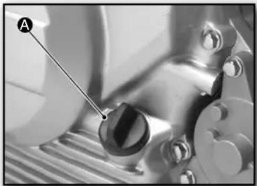
The oil level is checked using the dipstick attached to the filler plug located on the right-hand side of the crankcase.
The filler plug dipstick incorporates MIN and MAX marks for checking the oil level.
WARNING
This operation must be carried out with the engine switched off but still warm.
To inspect it correctly, make sure the motorcycle is in an upright position.
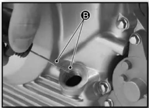
To check the level:
- Unscrew the threaded plug A.
- Clean the dipstick B.
- Screw the plug A in fully.
- Remove the plug A once again.
- Check the oil level on the marks on the dipstick B.
Topping up with oil:
- Top up with oil if necessary.
- Refit the oil plug A.
Type of oil: SAE 10-40
WARNING
The engine oil level must be between the MIN and MAX marks B.
Draining engine oil
WARNING
This operation must be carried out with the engine switched off but still warm.
ATTENTION
It is advisable to perform this operation while the engine is warm, and therefore care should be taken to avoid any possible burns.
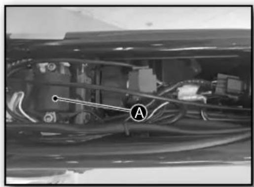
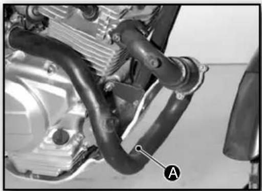
To drain the oil from the engine:
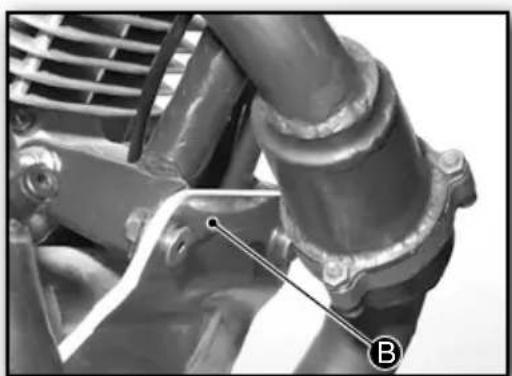
- Remove the exhaust pipe A.
- Remove the bottom crankcase protector B, using the 2 front screws and the 2 screws, 2 nuts and 2 washers at the rear.
- Place a container under the engine.
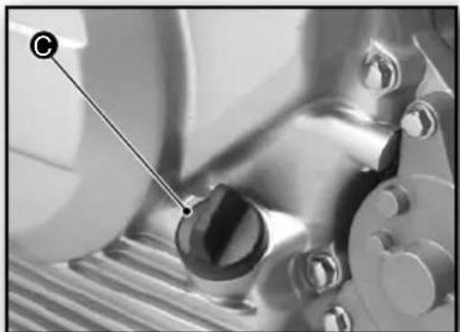
- Remove the filler plug - dipstick to aid draining.
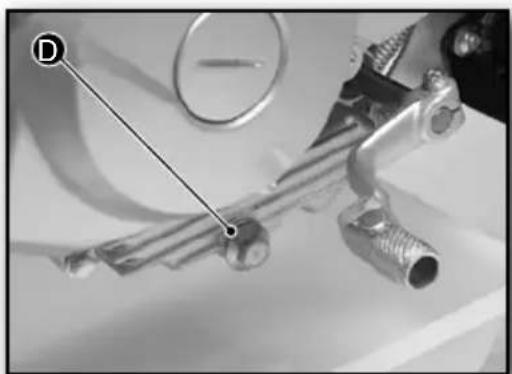
- Remove the drain plug bolt D.
- Wait a few minutes until all the oil has drained out.
- Refit the drain plug bolt .
- Refill with fresh oil.
- Refit the filler plug-dipstick
- Refit the bottom crankcase protector B.
- Refit the exhaust pipe A.
Type of oil: SAE 10-40
Quantity of oil: 900 cc
TIP
Check the level while proceeding with the oil filling, to make sure the maximum level is not exceeded.
WARNING
CHANGING THE ENGINE OIL FILTER requires technical knowledge and should therefore be done by an Official Sherco Service Centre.
INDICE
SHERCO
■ FRANÇAIS P.1
■ ENGLISH P.35
■ ESPÁNOL P.69
DEUTSCHP.103
SHERCO
Characteristicas techniques
DIMENSIONES