ENDURO 450-500 SEF (2026) - Motorcycle Sherco - Free user manual and instructions
Find the device manual for free ENDURO 450-500 SEF (2026) Sherco in PDF.


User questions about ENDURO 450-500 SEF (2026) Sherco
0 question about this device. Answer the ones you know or ask your own.
Ask a new question about this device
Download the instructions for your Motorcycle in PDF format for free! Find your manual ENDURO 450-500 SEF (2026) - Sherco and take your electronic device back in hand. On this page are published all the documents necessary for the use of your device. ENDURO 450-500 SEF (2026) by Sherco.
USER MANUAL ENDURO 450-500 SEF (2026) Sherco
text_image
Close-up of a mechanical device with visible label and numbered marker '1' pointing to a cable or wire.natural_image
Close-up of a mechanical assembly with gears and chains, no visible text or symbolsnatural_image
Close-up of a bicycle brake lever with labeled parts B and 1 (no text or symbols beyond labels)text_image
Close-up mechanical component with numbered parts labeled 1 to 5, likely for assembly or inspection purposes.text_image
Close-up of a mechanical component with numbered annotations pointing to parts 1 and 2.text_image
Close-up mechanical component with numbered labels pointing to specific partsnatural_image
Close-up of a microscope objective lens with visible aperture (no text or symbols)natural_image
Close-up of a smartwatch with a labeled sensor (no visible text or symbols)natural_image
Close-up of a mechanical component with a labeled section (no readable text or symbols)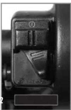
natural_image
Close-up of a mechanical component with a handle and internal structure (no visible text or symbols)Position 1. Courbe "soft".
Position 2. Courbe "hard".
ORGANES DE COMMANDES ET DE CONTRÔLE
COMMANDE AUX PIEDS : SÉLECTEUR DE VITESSE, BÉQUILLE, FREIN ARRIÈRE
natural_image
Close-up of a motorcycle's internal components, showing wheel, gear, and mounting bracket (no visible text or symbols)natural_image
Close-up of a mechanical assembly with visible tire and gear components (no text or symbols)text_image
39 SUB 37.1 RMINFig 4 Fonction DST
text_image
37 5:38 DST2 360.2 KMNFig 5 Fonction DST2
text_image
20.79 ART 2019 00:00 56 MAX KWH 34800.6Fig 8 Fonction ART
text_image
5:08 39 KM/H 37.1natural_image
Close-up of a white motorcycle's side panel with black seat and cable, no visible text or symbolsUse only unleaded fuel with an octane index of at least 95.
Filler cap
natural_image
Close-up of a gloved hand adjusting a mechanical component with wires and a rubber roller (no visible text or symbols)Open: Turn the cap counterclockwise. The opposite direction to the hands of a watch.
Close: Turn the cap clockwise. The same direction as the hands of a watch.
CONDUITE
natural_image
Close-up of a car's side panel with a numbered marker (1) pointing to a specific area, no visible text or symbols.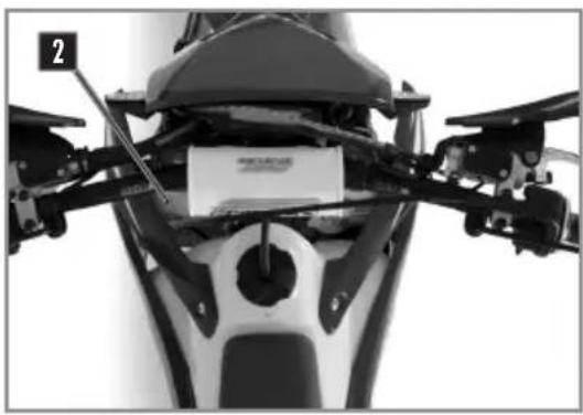
natural_image
Close-up of a motorcycle's head and torso assembly with visible mechanical components (no text or symbols)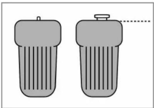
natural_image
Two gray cylindrical objects with ribbed surfaces, one with a small protrusion and the other with a dashed line (no text or symbols)Moto horizontal
! ATTENTION
natural_image
Close-up of a mechanical component with a white plastic bag attached, no visible text or symbolsnatural_image
Close-up of a car's front wheel and side panel, showing mechanical components and a numbered marker (1) in the corner.! ATTENTION
natural_image
Close-up mechanical assembly showing gears and hoses (no visible text or symbols)NOTE
natural_image
Close-up mechanical assembly showing gear and shaft components (no visible text or symbols)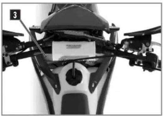
natural_image
Top-down view of a motorcycle's front wheel and side-mounted sensors (no visible text or symbols)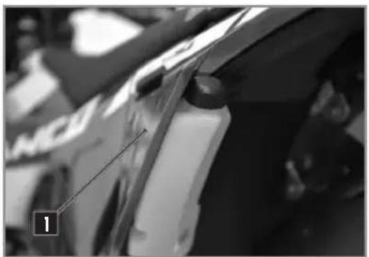
natural_image
Close-up of a car's front wheel and side brackets, no visible text or symbolsnatural_image
Close-up of a bicycle brake lever mechanism with a highlighted torque component (no text or symbols visible)text_image
Close-up of a mechanical component with labeled parts 1 and 2, likely indicating parts of a device or assembly.natural_image
Close-up of a mechanical assembly with no visible text or symbolsnatural_image
Close-up of a hand adjusting a mechanical component with a numbered label (2), no visible text or symbols beyond the number.natural_image
Close-up of mechanical components with no visible text or symbolsnatural_image
Close-up of mechanical components with no visible text or symbols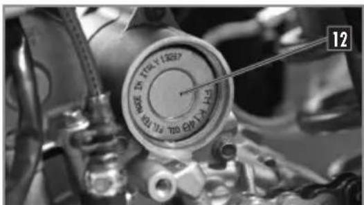
text_image
12text_image
12 TIRLY LREEF PILK TIN KEL PILK TIN KEL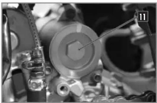
natural_image
Close-up of mechanical components with no visible text or symbols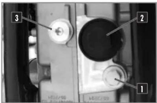
text_image
1 2 3text_image
Technical diagram showing mechanical components with labeled parts and a schematic of a piston assembly with arrows indicating motion or assembly.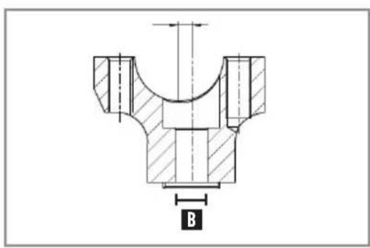
text_image
B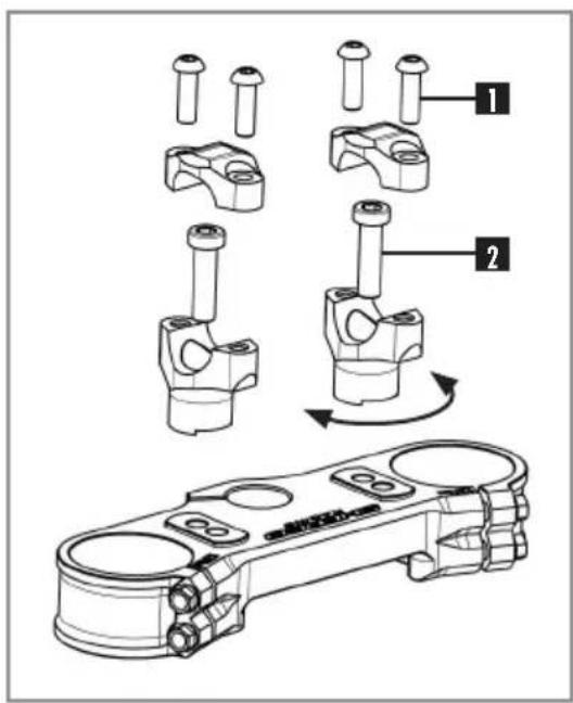
text_image
Technical diagram showing mechanical assembly steps with numbered components and a component photo labeled '机械臂'natural_image
Close-up of mechanical components with numbered annotations (1 and 2) indicating parts of a vehicle or assembly (no readable text or symbols)natural_image
Close-up of a mechanical assembly with visible gears and springs (no text or symbols)KAYABA RACING
natural_image
Close-up of a motorcycle's internal engine components, showing hoses and calipers (no visible text or symbols)KAYABA FACTORY
natural_image
Close-up of a motorcycle's front wheel and drivetrain components (no visible text or symbols)KAYABA RACING
natural_image
Close-up of mechanical components with no visible text or symbolsKAYABA FACTORY
natural_image
Close-up of a jet engine hub with visible components and no readable text or symbolsKAYABA
natural_image
Close-up of mechanical components with no visible text or symbolsnatural_image
Silhouette of a person riding a dirt bike with visible tire tracks and a labeled radius R3 (no text or symbols beyond the label)text_image
Technical diagram of a mechanical spring assembly with labeled parts 1 and 2natural_image
Mechanical shock absorber assembly with coiled spring and housing (no text or symbols visible)text_image
COTIE DIANA VILLI ITALYnatural_image
Front view of a motorcycle's side panel with labeled component '2' (no text or symbols on the body itself)natural_image
Close-up of a hand adjusting a vehicle's wheel assembly with tools (no visible text or symbols)natural_image
Close-up of gloved hands using a tool to adjust or install a mechanical component (no visible text or symbols)natural_image
Close-up of gloved hands adjusting a black helmet component with a small tag labeled '1' (no visible text or symbols)natural_image
Close-up of a car's seatbelt and wheel assembly (no visible text or symbols)text_image
Close-up of a mechanical component with numbered parts labeled 3 and 4, showing a tool inserted into a housing.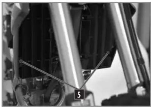
natural_image
Close-up of mechanical components with visible springs and shafts, no text or symbols presentnatural_image
Close-up of a car's front wheel and radiator assembly (no visible text or symbols)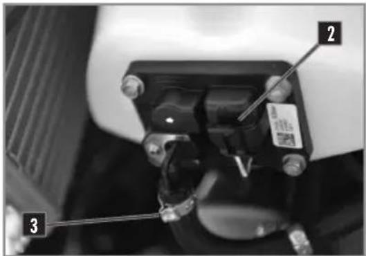
text_image
Close-up mechanical component with numbered parts labeled 1, 2, and 3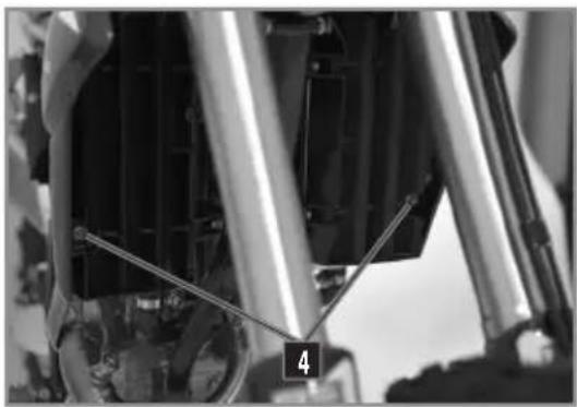
natural_image
Close-up of mechanical components with no visible text or symbolsnatural_image
Close-up of metallic mechanical components with black caps and a blue ring (no visible text or symbols)Moto sur trépied.
natural_image
Close-up of a motor dork wheel and tire assembly with motion arrows indicating rotational direction (no text or symbols)Moto sur trépied.
natural_image
Close-up of a mechanical assembly with wires and a labeled component (no readable text or symbols)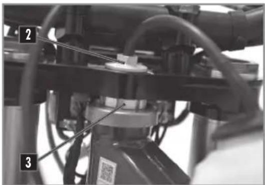
text_image
Technical diagram of a mechanical assembly with numbered components and labeled partsNETTOYAGE DE LA CHAÎNE

natural_image
Diagram of a mechanical linkage system with spray gun spraying through a chain (no text or symbols)CONTRÔLE DE LA TENSION DE CHAÎNE
text_image
50mmMoto sur trépied.
Desserrer les vis 1.
Desserer la vis de colonne de direction 2.
| Vis de direction | M20 | 30Nm |
natural_image
Close-up mechanical assembly showing a clamping mechanism with no visible text or symbolsRÉGLAGE EMBRAYAGE
text_image
A 1! ATTENTION
natural_image
Close-up of a mechanical lever handle with a circular arrow indicating cycle (no text or symbols)natural_image
Mechanical assembly diagram showing a vehicle's suspension system with labeled components (no readable text or symbols)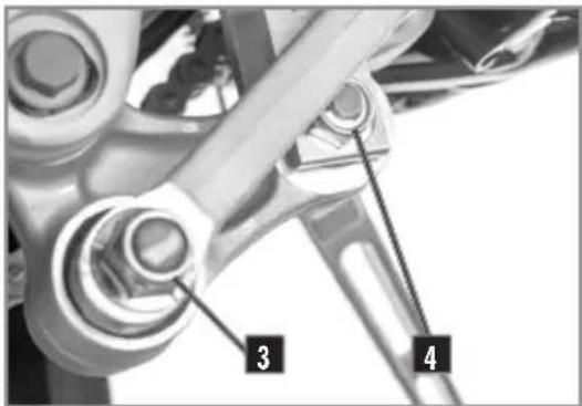
text_image
3 4REMONTAGE DE L'AMORTISSEUR
natural_image
Close-up of mechanical components with numbered annotations (1 and 2), no readable text or symbols beyond labels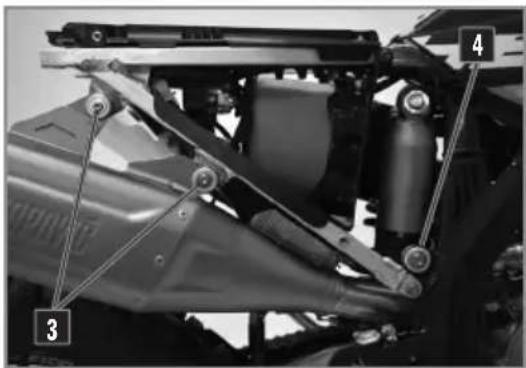
text_image
Technical diagram of a vehicle's suspension system with numbered components labeled 3 and 4Moto sur trépied.
text_image
Close-up mechanical component with numbered labels pointing to features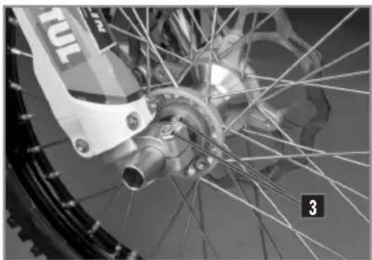
natural_image
Close-up of a bicycle wheel with visible tire, hub, and spokes (no text or symbols)REMONTAGE DE LA ROUE AVANT
text_image
Labeled mechanical component diagram showing three numbered parts of a vehicle wheel assemblyMoto sur trépied.
natural_image
Close-up of hands assembling a mechanical component with labeled parts (1 and 2), no visible text or symbols beyond labels.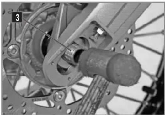
natural_image
Mechanical assembly diagram showing a bicycle wheel and gear mechanism (no text or symbols visible)natural_image
Close-up of a bicycle wheel with gear and hub, showing mechanical components and mounting holes (no text or symbols visible)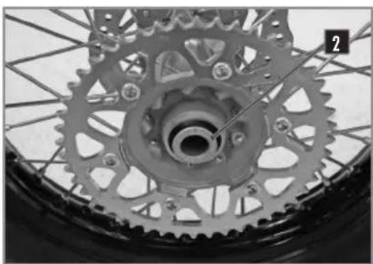
natural_image
Close-up of a bicycle wheel with visible teeth and central hub (no text or symbols)natural_image
Close-up of a bicycle's wheel and gear assembly, showing tread pattern and chain (no text or symbols visible)natural_image
Close-up of a bicycle wheel assembly with visible components and structural details (no text or symbols)natural_image
Close-up of a bicycle tire with a pressure gauge and cable, no visible text or symbolsnatural_image
Close-up of hands using a screwdriver to adjust the wheel rim of a bicycle tire (no text or symbols visible)natural_image
Close-up of a bicycle brake lever with labeled component A (no text or symbols beyond label)natural_image
Close-up of a bicycle brake lever mechanism with handle and grip (no visible text or symbols)natural_image
Close-up of a small electronic device with black casing and circular lens, partially covered by hands (no visible text or symbols)Mettre le bocal en position horizontale.
natural_image
Close-up mechanical assembly showing two labeled parts (1 and 2) with no visible text or symbolstext_image
Technical diagram of a mechanical assembly with numbered components, likely for assembly or maintenance reference.natural_image
Close-up of a mechanical component with a central bore and flange, partially visible in hand (no text or symbols)text_image
Close-up of a mechanical component with labeled parts 1 and 2, showing hand positioning and assembly details.natural_image
Close-up of a mechanical component with a labeled section 'A' and a central knob (no readable text or symbols beyond label)FREINS
DÉMONTAGE DES PLAQUETTES DE FREIN AVANT ET ARRIÈRE

text_image
Technical diagram of a mechanical assembly with numbered components labeled 1 and 2text_image
Close-up mechanical diagram of a bicycle frame with labeled parts 1 and 2CONTRÔLE DES PLAQUETTES DE FREIN AVANT ET ARRIÈRE
natural_image
Simple line diagram of a rectangular object with an arrow labeled 'A' and a horizontal line, no text or symbols present.text_image
Technical diagram of a mechanical assembly with numbered components labeled 1 and 2text_image
Labeled mechanical component diagram showing parts numbered 1 and 2, likely for assembly or maintenance instructions.text_image
Close-up mechanical component with numbered annotations pointing to parts 2 and 3natural_image
Close-up of a mechanical component with a labeled sensor or sensor device (no readable text or symbols)natural_image
Close-up of a mechanical component with no visible text or symbols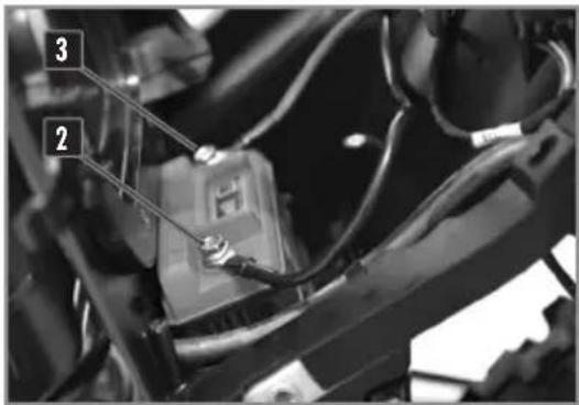
text_image
Close-up of a mechanical component with numbered annotations pointing to parts 2 and 3.natural_image
Close-up of a car's front wheel assembly with visible wiring and components (no text or symbols)natural_image
Close-up of a hand installing or adjusting electronic components in a circuit board (no visible text or symbols)natural_image
Close-up of a motorcycle's front wheel and drivetrain components (no visible text or symbols)natural_image
Close-up of a motorcycle's front wheel assembly with visible hoses and levers (no text or symbols)ENTRETIEN CIRCUIT ÉLECTRIQUE
REMONTAGE DE LA PLAUE PHARE
natural_image
Close-up of a mechanical component with numbered parts (1 and 2) and no visible text or symbolsnatural_image
Close-up of a motorcycle's front wheel and side gear assembly (no visible text or symbols)natural_image
Close-up of a mechanical assembly with labeled component '2' (no readable text or symbols)ENTRETIEN CIRCUIT ÉLECTRIQUE
RÉGLER LA PORTÉE DU PHARE
natural_image
Close-up of a motorcycle's front wheel and rear seat assembly (no visible text or symbols)natural_image
Close-up of a hand holding a handheld electronic device with wires and a coin, no visible text or symbols.We want to thank you for the trust that you have placed in us by purchasing this product.
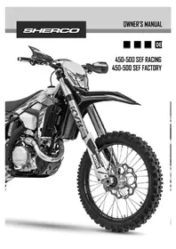
You are now the owner of a SHERCO 450-500 SEF. All the pleasures of driving are promised to you if you follow the advice and instructions that SHERCO has set in this manual, and ride it in compliance with the applicable traffic laws.
This manual explains the operation, inspection, basic maintenance and focus of your SHERCO. If you have any questions about this manual or your machine, you should contact your SHERCO dealer: www.sherco.com / under «Dealers».
Be sure to carefully read this manual in its entirety before using your machine.
To keep your SHERCO in perfect condition for many years, perform all of the care and maintenance described in the manual.
(The vehicle you purchased may differ slightly from the vehicle presented in this manual.)
SHERCO reserves the right to make changes without providing notice.
Please note that the optimum performance of your SHERCO will be obtained after a short break-in period (approximately 10 hours).
SERIAL NUMBER REGISTRATION
Save the serial numbers of the vehicle in a safe location
Dealer stamp.
Frame number (p.91)
Type and serial number of the motor (p.91)
SUMMARY
Technical Specifications 86
Description of the vehicle 90
Location of the serial numbers 91
Control devices and controls 92
Hand operated controls: Clutch lever, front brake lever and control switches 92
Foot controls: gear selector, side stand, rear brake ..... 95
Motorcycle computer instructions 96
Opening and closing the fuel tank 100
Riding the motorcycle 101
Safety information ....102
Cooling System ....103
Servicing the cooling system 103
Draining the coolant 104
Filling the coolant 105
Motor settings 106
Checking the play in the throttle cable 106
Motor maintenance 107
Checking the engine oil level 107
Draining the engine oil and removing the oil filter ..... 108
Refilling the engine whit oil 109
Adjusting the chassis 110
Handlebar position 110
Adjusting the steering angle 111
Basic setting of the chassis according to the rider weight ... 111
Setting the fork compression 112
Fork rebound adjustment 112
Adjusting the rear shock low-speed compression setting ... 113
Adjusting the rear shock high-speed compression setting .. 113
Rebound damper 114
Setting the rear shock sag 114
Setting the riding sag 114
Rear shock Kayaba 115
Changing the shock spring 115
Chassis maintenance ....116
Removing the seat 116
Reinstalling of the seat 116
Removing the air filter 116
Cleaning the air filter 117
Reinstalling the air filter 117
Removing the fuel tank 118
Reinstalling the fuel tank 119
Purging the air from the forks 120
Cleaning the fork dust seals 120
Checking the play of the steering head bearings 120
Adjusting the steering head bearing play 121
Cleaning the chain 121
Checking the chain tension 121
Adjusting the chain tension 122
Adjusting the cluch lever 122
Checking the clutch fluid level 123
Removing the rear shock 124
Reinstalling the rear shock 124
Wheels, tires 125
Removing the front wheel 125
Reinstalling the front wheel 125
Removing the rear wheel 126
Reinstalling the rear wheel 126
Checking the tire pressure 127
Checking for wear and damage 128
Cheching spoke tension 128
Brakes 129
Checking the front brake lever adjustment 129
Adjusting the front brake lever 129
Checking the front brake fluid level 129
Filling the front brake reservoir with brake fluid .....130
Adjusting the position of the rear brake pedal 130
Checking the travel of the rear brake pedal 130
Adjusting the travel of the rear brake pedal 131
Checking the rear brake fluid level 131
Filling the rear brake reservoir with brake fluid .....131
Removing the front and rear brake pads 132
Checking the condition of the brake pads 132
Reinstalling the front and rear brake pads 132
Electrical system maintenance ....133
Removing the battery 133
Reinstalling the battery 134
Charging the battery 134
Replacing the main fuse 135
Replacing the fuse for the lights 135
Removing the headlight housing 135
Reinstalling the headlight housing 136
Replacing the headlight bulb or the pilot lamp 136
Adjusting the headlight beam 137
Replacing the motorcycle computer battery 137
Washing and storage ....138
Washing the bike 138
Storing the bike 138
Recommissioning after storage 138
Maintenance schedule 139
Tightening torques ....142
Technical specifications 500 Supermotard .....146
Maintenance schedule 500 Supermotard ......148
Warranty 151
TECHNICAL SPECIFICATIONS
| DIMENSIONS | |
| Overall length | 2260 mm |
| Overall width | 820 mm |
| Seat height | 950 mm |
| Wheelbase | 1490 mm |
| Ground clearance | 355 mm |
| MOTOR 450 SEF 500 SEF | ||
| Type | Single cylinder 4 stroke liquid cooled | |
| Displacement | 449,4 cc | 449,4 cc |
| Bore / Stroke | 95 X 63,4 | 95 X 63,4 |
| Compression ratio | 12.30 : 1 | 12.30 : 1 |
| Distribution | 4-valve DOHC chain drive | |
| Starting System | Electric starter | |
| Intake valve diameter | 38 mm | |
| Exhaust valve diameter | 30,5 mm | |
| Intake valve cold clearance | 0.15-0.2mm | |
| Exhaust valve cold clearance | 0.2-0.25mm | |
| Spark plug | NGK LMAR9E-J | |
| Spark plug gap | 0.7 mm | |
| Electronic injection | SYNERJECT | |
| Alternator | 12V, 220W | |
| Engine oil | 1,1 litre SAE 10W60 | |
| TRANSMISSION | |
| Type | Manual |
| Clutch | Multi disc clutch in oil bath, hydraulically operated |
| Primary drive | 25 : 68 |
| Gearbox | 6 speed |
| Secondary drive | 14 X 50 |
TECHNICAL SPECIFICATIONS
CHASSIS
| Frame | Semi-perimeter CrMo steel with aluminum subframe |
| Fork | KAYABA USD ∅48mm Closed cartridge (Factory)KAYABA USD ∅48mm Open cartridge (Racing) |
| Rear suspension | KAYABA suspension with separate cylinder |
| Travel front/rear | 300/330mm |
| Front brake disc | Disc ∅260mm |
| Rear brake disc | Disc ∅220mm |
| Disc brakes wear limit | 2.7mm avant et 3.6mm back |
| Front tire | 90/90-21'' |
| Rear tire | 140/80-18'' |
| Pressure off-road front / rear | 0,9 bar |
| Fuel tank capacity with reserve | 9.7L with 1L of reserve |
| Fuel requirement | Unleaded gasoline with an octane index of at least 95 |
ELECTRICAL EQUIPMENT
| Battery | BS BSLi-02 Lithium | 12V 2Ah |
| Headlight | LED | - |
| Pilot | LED | - |
| Rear tail / stop | LED | |
| Flasher | R10W | 12V 10W |
| Speedometer battery | CR 2032 | Battery voltage: 3V |
| Plate light | W5W | 12V 5W |
ADJUSTMENTS - KAYABA USD (FACTORY) ∅48MM
| Compression | Comfort | 20 clicks back |
| Standard | 12 clicks back | |
| Sport | 8 clicks back | |
| Rebound | Comfort | 18 clicks back |
| Standard | 12 clicks back | |
| Sport | 10 clicks back | |
| Spring stiffness | Rider weight: 65-75kg | 4.2N/mm |
| Rider weight: 75-85kg | 4.4N/mm (original) | |
| Rider weight: 85-95kg | 4.6N/mm | |
| Type of oil | KAYABA 01M | 345 CC |
TECHNICAL SPECIFICATIONS
| ADJUSTMENTS - KAYABA USD (RACING) ∅48MM | ||
| Compression | Comfort | 18 clicks back |
| Standard | 14 clicks back | |
| Sport | 12 clicks back | |
| Rebound | Comfort | 14 clicks back |
| Standard | 12 clicks back | |
| Sport | 10 clicks back | |
| Spring stiffness | Rider weight: 65-75kg | 4.2N/mm |
| Rider weight: 75-85kg | 4.4N/mm (original) | |
| Rider weight: 85-95kg | 4.6N/mm | |
| Type of oil | KAYABA 01M | 345 cm3 |
| Oil level measurement (fork compressed and spring removed) from the top of the fork tube | 120 mm | |
| ADJUSTMENTS - KAYABA SHOCK ABSORBER | ||
| Compression | Comfort | 20 clicks back |
| Standard | 14 clicks back | |
| Sport | 12 clicks back | |
| Rebound | Comfort | 2,5 turns back |
| Standard | 1,5 turns back | |
| Sport | 1 turn back | |
| Preload | Comfort | 15 clicks back |
| Standard | 13 clicks back | |
| Sport | 11 clicks back | |
| Spring stiffness | Rider weight: 65-75kg | 48N/mm |
| Rider weight: 75-85kg | 50N/mm (original) | |
| Rider weight: 85-95kg | 54N/mm | |
TECHNICAL SPECIFICATIONS
CLEANING PRODUCTS AND CONSUMABLES
| Engine oil | SAE 10W60 | Motorex ^ Cross Power 4T |
| Coolant | Motorex ^ Coolant M3.0 | |
| Brake Fluid | DOT 4 | Motorex ^ Brake Fluid Dot 4 |
| Fork oil | KAYABA 01M | |
| Shock oil | KAYABA K2C | |
| Aerosol chain lube | Motorex ^ ChainLube OffRoad | |
| Air filter cleaner | Motorex ^ Air Filter Cleaner | |
| Air filter lubricant | Motorex ^ Air Filter Oil | |
| Plastic cleaner | Motorex ^ Quick Cleaner | |
| Wheel Cleaner | Motorex ^ Wheel Cleaner | |
| Disc brake Cleaner | Motorex ^ Brake Clean | |
| Universal lubricant | Motorex ^ Bike Grease 2000 |
DESCRIPTION OF THE VEHICLE
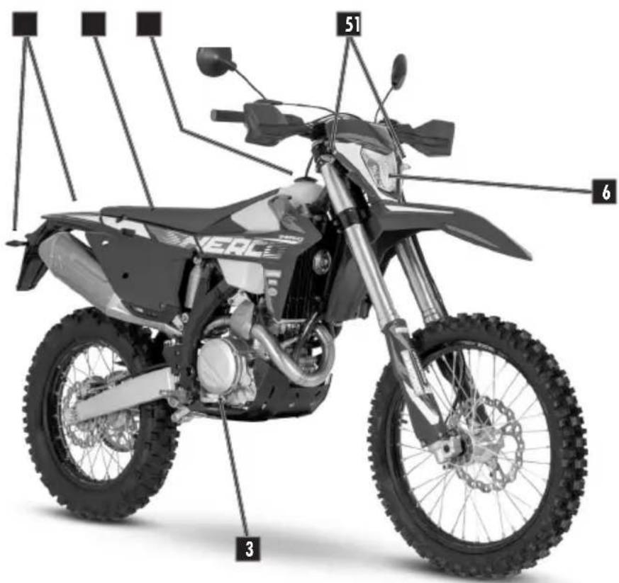
Right side
1 - Rear turn signals.
2 - Seat.
3 - Rear brake pedale.
4 - Tank.
5 - Front turn signals.
6 - Headlight.
text_image
51 6 3Left side
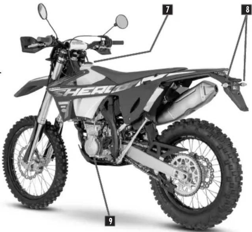
7 - Fuel tank cap.
8 - Rear light
(tail / brake light / plate light).
9 - Gear selector pedal.
text_image
7 8 9DESCRIPTION OF THE VEHICLE
text_image
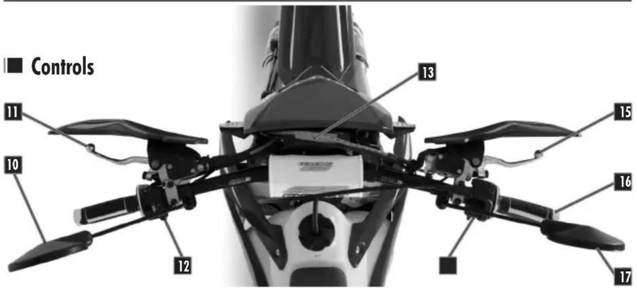
Controls 11 10 12 13 15 16 1710 - Left mirror.
11 - Clutch lever.
12 - Left switch.
13 - Dashboard.
14 - Right switch.
15 - Front brake lever.
16 - Throttle grip.
17 - Right mirror.
LOCATION OF THE SERIAL NUMBERS
■ Vehicle serial number location
text_image
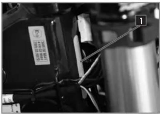
11 The serial number of the vehicle is stamped on the right side of the steering tube.
Engine serial number location
natural_image
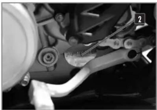
Close-up of a mechanical assembly with visible gears and tubing (no text or symbols)2 The engine serial number is stamped on the left side of the engine housing.
CONTROL DEVICES AND CONTROLS
HAND OPERATED CONTROLS:
CLUTCH LEVER, FRONT BRAKE LEVER AND CONTROL SWITCHES
Clutch lever
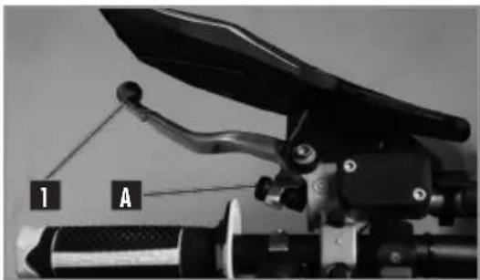
text_image
1 AThe clutch lever 1 is on the left handlebar and has an adjustment screw A.
Front brake lever
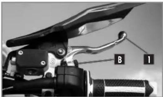
text_image
B 1The front brake lever 1 is on the right side of the handlebar and has an adjustment screw B.
Left switch
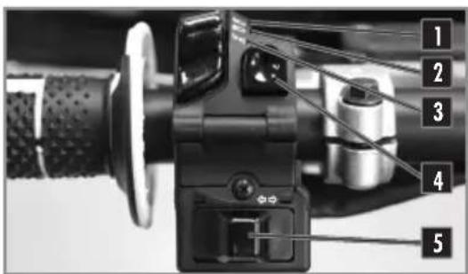
text_image
Close-up of a mechanical device with numbered parts labeled 1 to 5, showing internal components and wiring.1 High beam (Headlight)
2 Low beam (Headlight)
3 Side light (Night-light)
4 Horn
5 Turn light
Light switch On/Off (Racing)
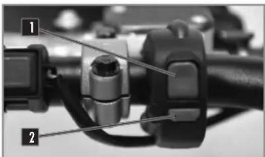
text_image
Close-up mechanical component with numbered labels pointing to featuresTwo possible positions:
Position ON 1 : All lights are on.
Position OFF 2 : All lights are off.
Rigth switch
text_image
Close-up mechanical component with numbered labels pointing to specific partsDashboard
text_image
1 2 3 4 SASERKey switch
text_image
POSITION 1 POSIT 2Turn light switch
text_image
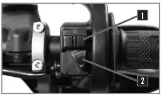
1 2 31 Starter button.
2 Injection system mapping selection button.
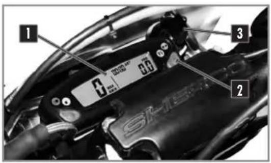
1 Dashboard.
2 Mode selection button.
3 Key switch.
Available with the homologation kit.
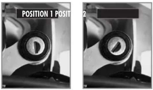
The main switch has two positions:
Position 1.
The engine is off and can not be started.
Position 2.
The motor can be started.
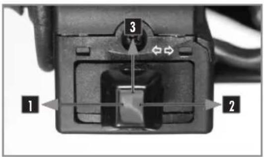
1 Left turn position.
2 Right turn position.
3 Off position.
CONTROL DEVICES AND CONTROLS
KEYLESS system
The bike has a "Keyless" system. It allows the bike to start without a key or ON/OFF switch. It automatically turns on and it turns off after 30 seconds of non-use of the bike. Lithium-ion batteries are far lighter than lead batteries, have a low self-discharge rate, and have more starting power at temperatures over 15^ (60°F). At low temperatures, however, the starting power of lithium-ion batteries drops to below that of lead batteries.
Multiple starting attempts may be needed. Press the electric starter button for 5 seconds, and wait 30 seconds between attempts. The pauses are necessary so that the created heat can distribute through the lithium-ion battery and the battery is not damaged.
If the charged lithium-ion battery does not or only weakly turns over the electric starter when temperatures are below 15 ^ ( 60 ^ ), then the battery is not faulty, but needs to be warmed up internally to increase its starting power (current output). The starting power increases as the battery warms up.
■ Egine emergency stop
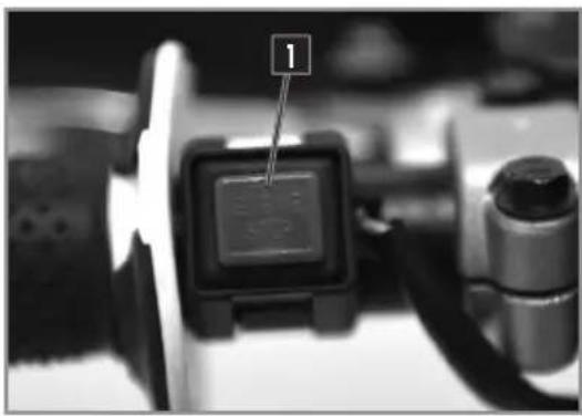
natural_image
Close-up of a digital display with a numbered annotation '1' pointing to it, no readable text or symbols present.Two possible positions:
The button 1 released: In this position, the motorcycle can be be started.
The button 1 pressed: the motorcycle is switched off when running and the motorcycle cannot be started.
■ Injection system mapping switch
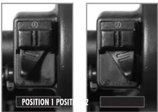
natural_image
Close-up of two mechanical component parts labeled POSITION 1 and POSITION 2, showing internal structural details (no readable text or symbols beyond labels)Position 1. "Soft".
Position 2. "Hard".
CONTROL DEVICES AND CONTROLS
FOOT CONTROLS:
GEAR SELECTOR, SIDE STAND, REAR BRAKE
Gear selector
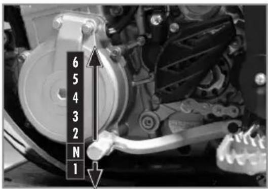
text_image
6 5 4 3 2 N 1The drawing shows the path of the gear selector for each of the 6 speeds.
Footbrake
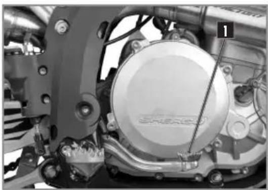
natural_image
Close-up of a mechanical assembly with visible components and a numbered marker (1), no readable text or symbols present.1 Rear brake pedal.
Side stand
natural_image
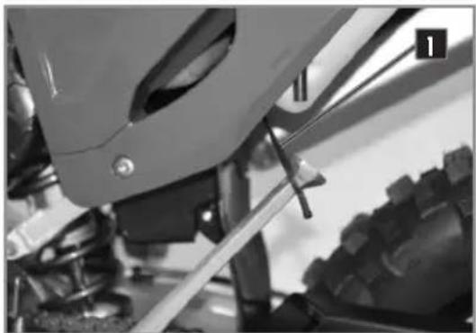
Close-up of a mechanical assembly with visible gears and mounting brackets (no text or symbols)Remove the rubber safety latch 1, using your foot on the shaft unfold it until it supports the weight of the bike.
WARNING
- The stand has a security system which automatically folds the stand when the bike is moved into an upright position.
- The stand is designed to support the weight of the motorcycle only.
CONTROL DEVICES AND CONTROLS
MOTORCYCLE COMPUTER INSTRUCTIONS
text_image
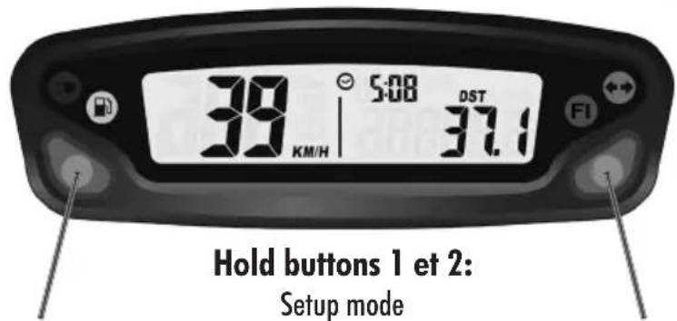
39 KM/H 5:08 DST 37.1 F1 Hold buttons 1 et 2: Setup modeCAUTION
To avoid water water infiltration, respect a minimum distance distance of 20 cm.
Button 1:
Change screens 1,2,3
Hold button 1:
Screen 1: DST Adjust
Screen 2: DST2 Adjust
Button 2:
Change screens 1,2,3
Hold button 2:
Screen 1: Reset DST
Screen 2: Reset DST2
Screen 3: Reset MAX/ AVG
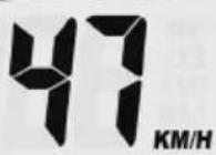
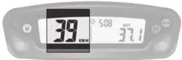
Screen 1: Speed, Clock, Distance 1
Screen 2: Speed, Clock, Distance 2
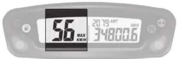
Screen 3: Alternating AVG/MAX speed, Accumulated run time, ODO

Turn indicator

High beam

Fuel injection (MIL): EFI problem

Low fuel
Button mode
The vehicle doesn't need to be switched on.
Left button:
Switch between the three display screens Enter adjustable trip distance mode ( DST and DST2) Allows you to decrement the distance in DST.
Right button:
Allows you to navigate between the different screens Reset DST/DST2, speed MAX/AVG (hold button 3s) Allows to increment the distance in DST.
text_image
39 KM/W SUB OPT 37.1Fig 1 SPD function
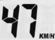
SPD function Current speed (screens 1 and 2):
displays the current speed of the vehicle.
The speed can be displayed in km/h (default) or mph. (p.99).
text_image
56 MAX KM/W 2019 ART 00:00 34800.6Fig 2 MAX speed function
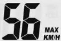
MAX speed (screen 3):
displays the maximum speed since the last reset was performed. The maximum speed can be displayed in km/h (default) or mph. (p. 99).
Reset to 0 → MAX Function → Hold the right Button down for 3 seconds → 0 → Reset to 0 done.
text_image
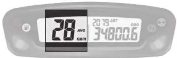
28 AVO KM/H 2019 ART ODO 34800.6Fig 3 AVG function
AVG function Average speed (screen 3):
the average speed of the vehicle since the last reset was performed.
The average speed is displayed in the chosen units, km/h (default) or mph(☐ p.99).
Reset to 0→AVG Function→Right button down for 3seconds→0→Reset to 0 done.
text_image
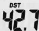
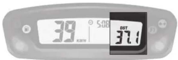
39 5:08 DST 37.1 KM/HFig 4 DST function
DST function (screen 1):
displays the mileage traveled by the vehicle since the last reset was performed.
The distance is displayed in the selected units, km/h (default) or mph. (p.99).
Reset to 0→DST Function→Hold the right.
Button down for 3seconds→0.0→Reset to 0 done.
text_image
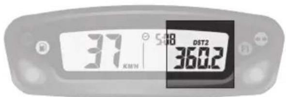
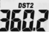
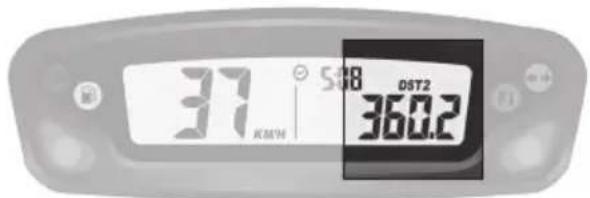
37 588 DST2 360.2 KMWhFig 5 DST2 function
DST2 function (screen 1):
displays the mileage traveled by the vehicle since the last reset was performed.
The distance is displayed in the selected units, km/h (default) or mph. (p.99).
Reset to 0→DST2 Function→Hold the right.
Button down for 3seconds→0.0→Reset to 0 done.
text_image
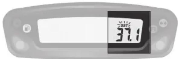
2007 37.1Fig 6 Adjustable trip distance function
DST and DST2 can be incremented or decremented by the user.
DST set up (screen 1)→Hold the left Button down for 3 seconds→DST» icon will flash→Hold left Button to decrement/ Hold the right Button to increment→ back to screen 1.
DST set up (screen 2)→Hold the left Button down for 3 seconds→DST2» icon will flash→Hold left Button to decrement/ Hold the right Button to increment → back to screen 2.
text_image
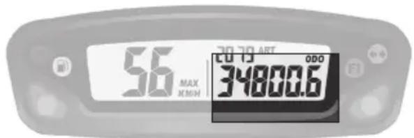
56 MAX CHEN 20 TO ART 34800.6 ODOFig 7 ODO function
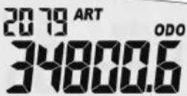
ODO function Odometer (screen 3):
displays the total mileage traveled by the vehicle. The total distance is displayed in the selected units, km/h (default) or mph. (p.99).
This information can not be reset to 0.
Beyond 399 999 km (or miles), the counter goes back to 0.
text_image
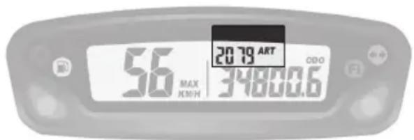
20.79 ART 2019 00:00 56 MAX EON 34800.6Fig 8 ART function
ART function Accumulated Ride Time (screen 3):
displays the hours of operation of the vehicle.
This information can not be reset to 0.
Until 99h59min → displayed in one minute increments. After 99h59min up to 9999h → displayed in one hour increments If the unit should reach 9999 hours of accumulated ride time, the display will stop incrementing, and will remain at that number.
text_image
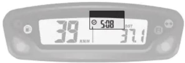
5:08 39 KM/H 37.1Fig 9 Clock function
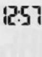
Clock function (screens 1 et 2):
displays clock information.

Fig 10 Low battery/ Low battery error function
Low battery/ Low battery error function:
→ When the battery voltage drops to less than 2.40V, the LO battery warning will turn on.
→ When the internal battery is critically low, the unit will only display a blinking «LO» icon.
Set up menu
| Left and right buttons pressed simultaneously for 3s activates the Set up mode | |
| Left button | Right button |
| Toggle between M/H and KM/H settingsToggle between 24 Hour et 12 Hour | |
| Decrement time of day value | Increment time of day value |
| Decrement maintenance reminder value | Increment maintenance reminder value |
The meter will automatically advance from one setting option to the next, after 5s of no button activation
| UNIT(Unit type) | LIFE(Wheel circumference) | PPr(Pulse per revolution) | (Clock format) (Clock setup) (Maintenance reminder) | ||
 Miles or kmDefault: kmDo not modify these settings Miles or kmDefault: kmDo not modify these settings | ↓12 or 24hDefault: 24h | ↓Clock setup Maintenance reminder setting (in hours) | ↓Default setting:5h (first oil change) | ||
| OFF:disabledSet the value | |||||
Maintenance reminder:
Allows user to define a countdown for maintenance operations.
When the maintenance countdown gets to zero, the maintenance icon will appear on the LCD.
Displaying the remaining accumulated ride time :
From main screen → hold the left button down for 3 seconds → the remaining value is displayed → no button activation → automatic return to screen 3.
Note :
If the maintenance reminder is turned off, the information displayed on the screen will be OFF.
Resetting the remaining accumulated ride time :
From main screen, hold the left button down for 3 seconds → the remaining value is displayed → hold the right button down for 3 seconds → the maintenance reminder is reset to zero (will begin the countdown again according to the maintenance interval already chosen in the set up menu).
CONTROL DEVICES AND CONTROLS
OPENING AND CLOSING THE FUEL TANK
Fuel
natural_image
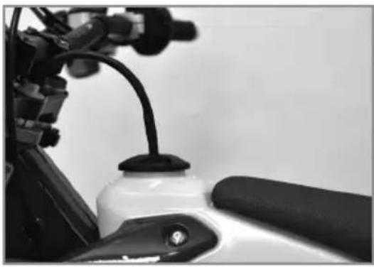
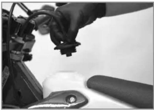
Close-up of a white motorcycle's side panel and rear-mounted cable, no visible text or symbolsUse only unleaded fuel with an octane index of at least 95.
Filler cap
natural_image
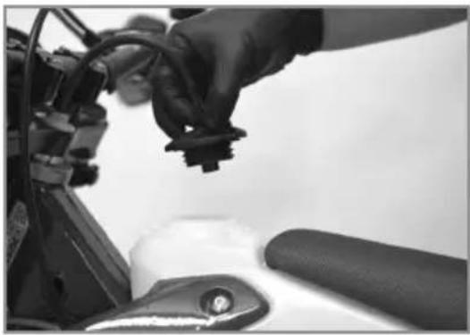
Close-up of a gloved hand adjusting a mechanical component with wires and a rubber roller (no visible text or symbols)Open: Turn the cap counterclockwise. The opposite direction to the hands of a watch.
Close: Turn the cap clockwise. The same direction as the hands of a watch.
Cold engine starting
- Set the gear selector to neutral.
- Pull the choke.
- Start the engine by pressing the starter button, without accelerating.
- Allow the engine to warm up for a few minutes.
- Push in the choke.
Hot engine starting
Follow the previous instructions without steps 2-4 and 5.
■ Shifting gears
- The positions of the gear selector are shown on (p.95).
- To find the neutral position, press the selector down into first gear (a resistance will be felt), then move the selector up slightly.
- Close the throttle before changing gears.
- Engage the lowest gear.
- Partially open the throttle while engaging the clutch.
Parking
- Stop the engine with the stop button. The Keyless system will automatically switch off the ignition after 30 seconds of non-use of the bike.
Become familiar with all of the controls and their functions before using the vehicle.
SAFETY INFORMATION
- Do not drive after consuming alcohol.
- Wear a helmet when using the vehicle.
- Keep the machine in good working order and maintain it properly so that it is reliable and safe for use.
- Gasoline is flammable, refuel the motorcycle when the engine is stopped.
- Exhaust fumes are toxic, you should never start the engine in a closed building.
- Always park the vehicle on a flat hard surface, do not park the vehicle on a slope or on soft ground. Always control the balance of the vehicle.
- Check the following every day before riding the motorcycle:
| Tires: | Wear and pressure. |
| Engine oil: | Level (p.107). |
| Gasoline: | Check the level and make sure there is no leaks. |
| Transmission chain: | Properly lubed and adjusted (p.122). |
| Direction of travel: | check for hard spots. |
| Brakes: | Operation, fluid leakage, brake pad wear (p.129 to p.133). |
| Throttle: | Proper operation (p.106). |
| Clutch: | Proper operation (p.122). |
| Electrical Equipment: | Operation of the horn and lights (p.92 to p.93). |
| Components (nut, bolts ...): | Verify that all components of the vehicle are properly tightened (p.146). |
If you experience a problem with any of the components of the motorcycle, consult the Service and Adjustments section of this manual or contact a Sherco dealer.
SERVICING THE COOLING SYSTEM
natural_image
Close-up of a person adjusting a car tire, no visible text or symbols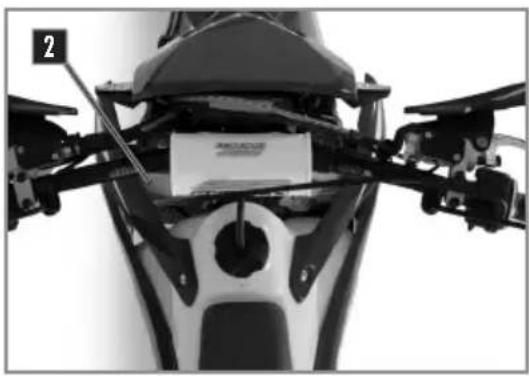
natural_image
Close-up of a motorcycle's head and front view showing mechanical components and a small paper label (no readable text or symbols)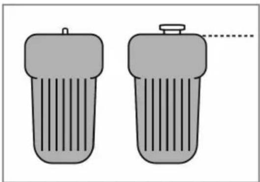
natural_image
Two identical gray cylindrical objects with ribbed surfaces, one with a small protrusion and the other with a dashed line (no text or symbols)Motorcycle horizontal
WARNING
- The hot liquid can cause severe injuries.
- The coolant is harmful.
- After contact with skin or eyes, or ingestion, or injuries caused by hot liquids: Consult a physician.
- Use protective gloves.
- Do not replace the coolant with water or other not approved fluids: it could damage your engine.
-
Follow these procedures carefully and always fill the engine with coolant when the engine is cold.
-
Place the bike upright on a horizontal surface.
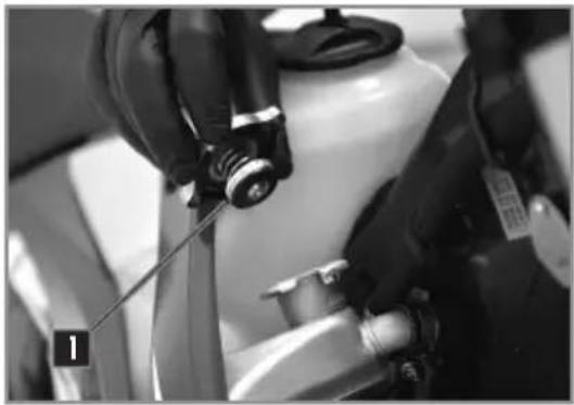
- Remove the cap 1.
Approved Coolant Motorex ^® Coolant M3.0
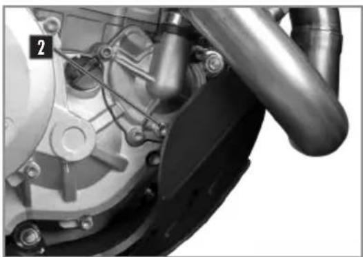
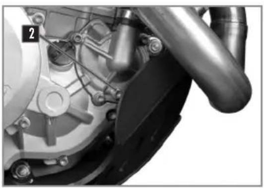
- Remove the bleed screw 2.
- Fill the radiator full so that there is no air in the system.
| Radiator Bleed screw | M6X8 8Nm |
Fill the coolant to the top of the radiator. Replace the cap 1 and check to make sure it is tight.
! ATTENTION
It is important to follow this procedure. The lack of fluid, or the presence of a pocket of air left in the radiator can cause serious damage to the engine.
natural_image
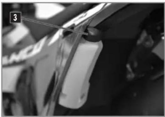
Close-up of a mechanical component with a white plastic bag attached, no visible text or symbolsCheck the fluid level in the expansion container. The liquid should reach the level on the container where it indicates "LEVEL MIN". If the level is not correct, unscrew the cap 3. Fill with fluid until it reaches the LEVEL MIN mark.
Approved Coolant Motorex ^® Coolant M3.0
Replace the cap 3.
natural_image
Close-up of a car's front wheel and side brackets, no visible text or symbolsWARNING
Make sure the motorbike is upright and on level ground.
- Place a container under the bike.
- Remove the cap 1 and screw 2.
- Allow the coolant to drain.
natural_image
Close-up mechanical assembly showing gears and springs (no visible text or symbols)NOTE
To protect the environment, dispose of the drained liquid to a collection point.
FILLING THE COOLANT
natural_image
Close-up mechanical assembly showing internal components and a numbered label (2), no readable text or symbols present.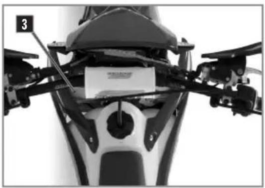
natural_image
Close-up of a motorcycle's front view showing structural components and a small paper label (no readable text or symbols)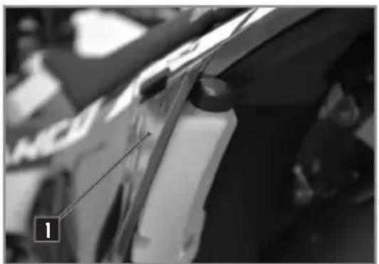
natural_image
Close-up of a car's front wheel and side brackets, no visible text or symbols- Replace the bleed screw 2 using a new seatt. - Refill the coolant into the radiator through the cap 1.
Approved Coolant Motorex ^® Coolant M3.0
- Fill coolant until is going out from the screw 3. - Put the screw 3 back in with a new seal.
Radiator bleed screw M6X45 8Nm
- Continue filling. - Fill until the coolant reaches the level (approximately 1.1 liters). - Put the bike on the side stand and follow the rest of the filling procedure (p.103). - Replace the cap 1.
CHECKING THE PLAY IN THE THROTTLE CABLE
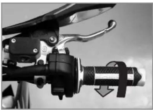
- Checking the throttle cable play
natural_image
Close-up of a bicycle brake lever mechanism with a highlighted shaft and handle (no text or symbols visible)With the handlebars facing straight ahead, check that the throttle twist grip functions properly.
Throttle cable play 2....4mm
If the cable play is not correct, adjust the accelerator throttle cable play.. (→ ci-dessous).
Start the bike and let it run at idle. Turn the handlebars and check that the idle speed is constant. If the speed changes, readjust the play in the throttle cable ( ci-dessous).
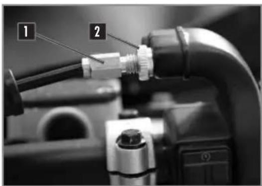
■ Adjusting the play in the throttle cable
text_image
Close-up of mechanical component with numbered labels pointing to a connector or fittingAdjust the tension of the gas cable at the handle with the tensioner 1.
Loosen locknut 2 and adjust the tension of the cable with the tensioner 1.
Once the desired play has been reached, tighten the lock nut 2.
MOTOR MAINTENANCE
CHECKING THE ENGINE OIL LEVEL
natural_image
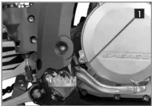
Close-up of a mechanical assembly with a circular component and a labeled part 'SHERO' (no readable text or symbols beyond label)- Make sure that the bike is on its two wheels, vertical and on a horizontal surface.
- Check the engine oil level by viewing the sight gage located on the clutch housing 1.
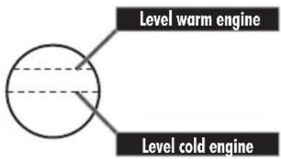
- Adjust the level according to the diagram shown below.
natural_image
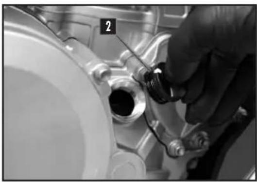
Close-up of a hand adjusting a mechanical component with a numbered label (2) on the pipe (no readable text or symbols beyond the label)If necessary add oil to achieve the correct oil level:
- Unscrew the engine oil filler cap 2 located on the clutch housing
text_image
Level warm engine Level cold engine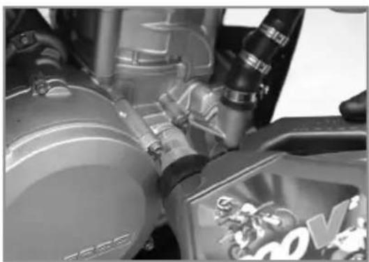
natural_image
Close-up of mechanical components with no visible text or symbolsTopping up the engine oil.
Engine Oil SAE 10W601,1L
WARNING
- Improper oil level can damage your engine.
- Do not use your bike if the level is below the minimum.
MOTOR MAINTENANCE
DRAINING THE ENGINE OIL AND REMOVING THE OIL FILTER
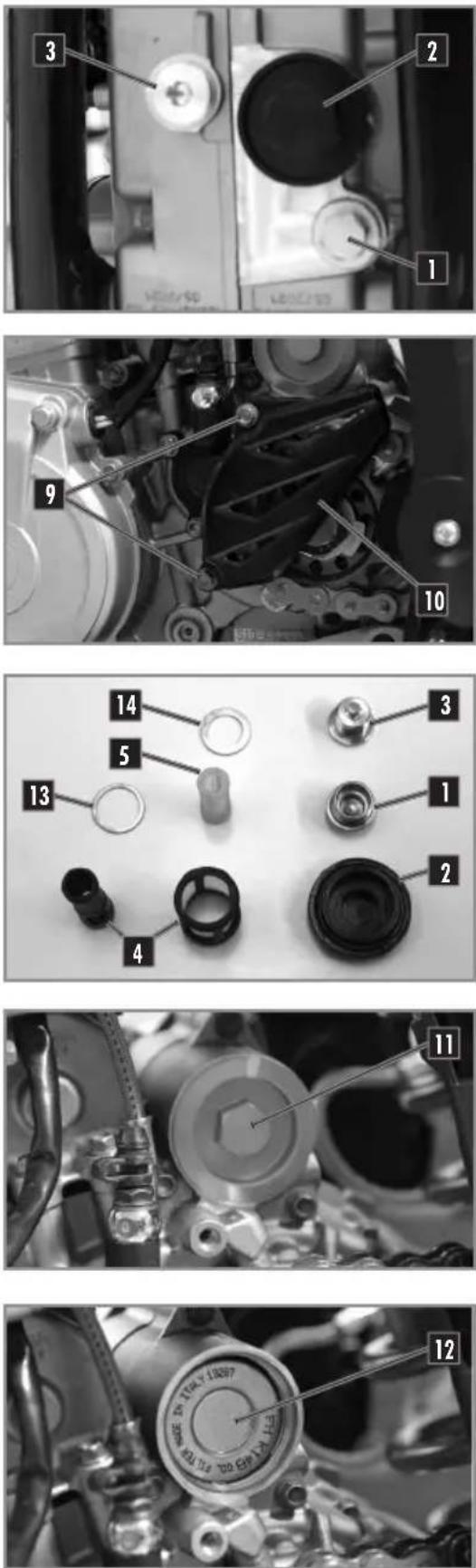
- When draining the oil the engine should be warm.

WARNING
Use protective gloves
- Position the motorcycle upright on a level surface.
- Place a container under the bike to catch the old oil.
- Remove the drain plug 1 and 2.
- Remove the magnetic drain plug 3.
- Remove the pre-filter 4 and 5.
- Allow the oil to drain
-
Remove the screws 9 and remove the chain guard 10.
-
Remove the oil filter cover 11.
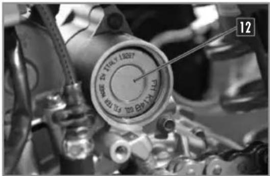
- Use a hook to remove the oil filter 12.
- Let the oil drain.
- Clean the drain plugs 1, and with a degreaser.
- Clean and inspect the pre-filters 4 and 5 and change them if necessary.
MOTOR MAINTENANCE
REFILLING THE ENGINE WITH OIL
text_image
12 MODE TO TILLY LEEP 100 10.5 100 10.5 100 10.5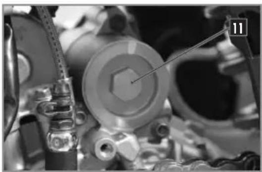
natural_image
Close-up of mechanical components with no visible text or symbols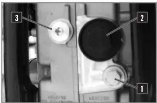
text_image
1 2 3- Install a new oil filter 12, install in the direction shown in the photo.
- Install the cap 11 using a new O-ring.
Oil Filter cap M45 15Nm
- Install the plug 3 using a new gasket.
Magnetic drain plug M12 15Nm
- Install the pre-filters 4 and 5 the drain plugs 1 and 2 with new seal ▪ and ▪.
Drain plug 1 M18 15Nm Drain plug 2 M21 20Nm
- Remove the engine oil filler cap 2 (p.107).
- Fill the engine with oil.
Motor oil 1,1L SAE 10w60
- Install the engine guard.
- Check the oil level in the sight gage.
- Add additional oil if necessary.

NOTE
The oil filter 12 should be replaced at each oil change.

WARNING
To protect the environment, oil, oil filters and used material must be deposited in a collection center and not down the drain or in the wild.
HANDLEBAR POSITION
text_image
Technical diagram showing mechanical components with labeled parts and a schematic of a piston-cylinder assembly with arrows indicating motion.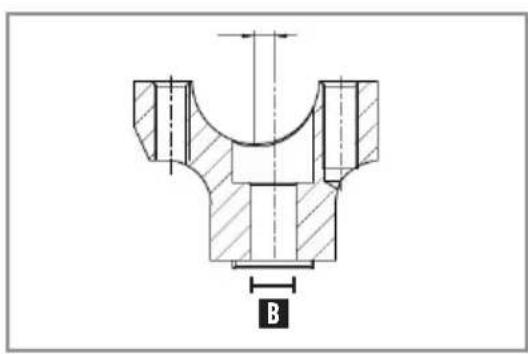
text_image
B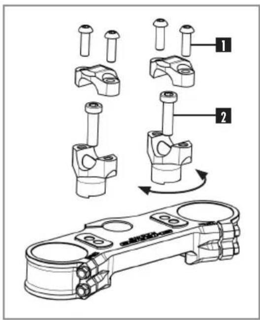
text_image
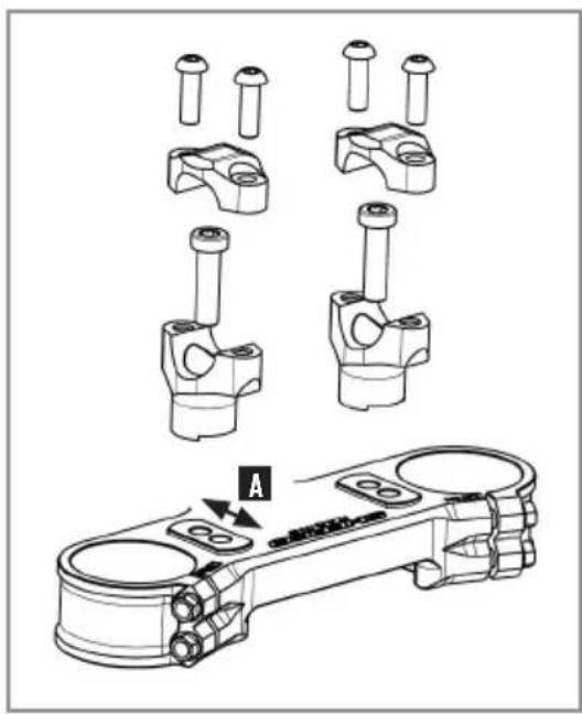
Technical diagram showing mechanical assembly steps with numbered components and a component photo labeled '机械臂'The triple clamps have two holes separated by a distance A.
| Distance between holes A | 13mm |
The handlebar clamps are offset by a distance B.
| Handlebar offset B | 4mm |
The bike comes standard with the handlebars in the rear most position.
Remove the four screws 1. Remove the handlebar top clamps and remove the handlebar.
Remove the two screws 2. Remove the lower clamps and place them in the desired position.
| Handlebar lower clamp | M10x35 | 40Nm | Loctite® 243TM |
Replace the handlebars and top clamps.
Replace the four screws 1 and tighten evenly.
| Handlebar clamps fixing screws | M8x25 | 25Nm |
The handlebars can be rotated forward and rearward in the clamps.
ADJUSTING THE CHASSIS
ADJUSTING THE STEERING ANGLE
natural_image
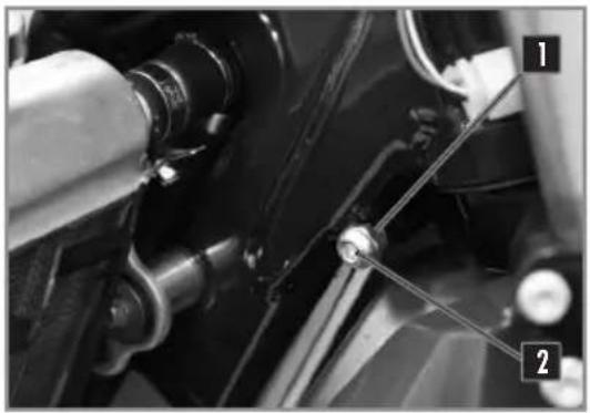
Close-up of mechanical components with numbered annotations (1 and 2) pointing to specific parts, no readable text or symbols present.The steering angle can be changed using the set screws located on the bottom of the steering column. Loosen the nut 1 and tighten the screw 2 until you have the steering angle desired.
Tighten the nut and do the same operation on the other side.
| Steering angle lock nut | M8 20Nm |
BASIC SETTING OF THE CHASSIS ACCORDING TO THE RIDER WEIGHT
If the weight of the rider is above or below the standard, compensate by changing the stiffness of the springs (forks and shock).
| Standard weight of therider (with equipment) | 75 to 85kg |
SETTING THE FORK COMPRESSION
natural_image
Close-up of a mechanical assembly with visible gears and springs (no text or symbols)KAYABA RACING
natural_image
Close-up of a motorcycle's internal components and brake lever (no visible text or symbols)KAYABA FACTORY
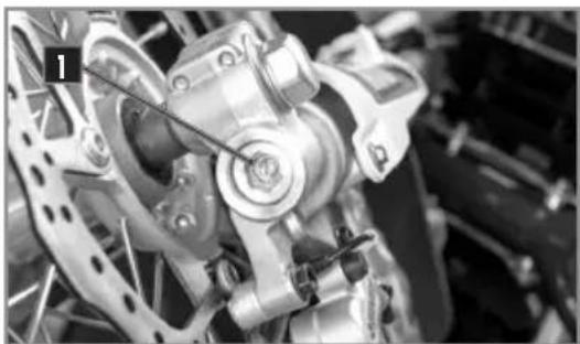
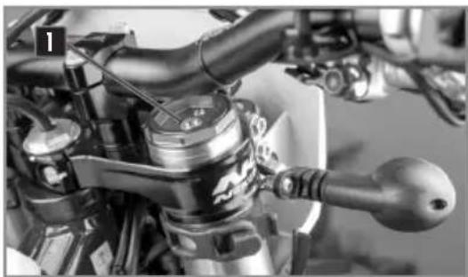
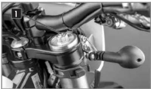
Screws 1 determine the behavior of the fork when it is compressed. Turning in the screwclockwise increases the hydraulic force (and vice versa).
Turn screw1 clockwise to the stop and go back the number of clicks required.
| Setting compression KAYABA suspension (Racing) | Comfort | 18 clicks |
| Standard | 14 clicks | |
| Sport | 12 clicks | |
| Réglage de compression KAYABA (Factory) | Comfort | 20 clicks |
| Standard | 12 clicks | |
| Sport | 8 clicks |
FORK REBOUND ADJUSTMENT
natural_image
Close-up of a motorcycle's front wheel and drivetrain components (no visible text or symbols)KAYABA RACING
natural_image
Close-up of mechanical components with no visible text or symbolsKAYABA FACTORY
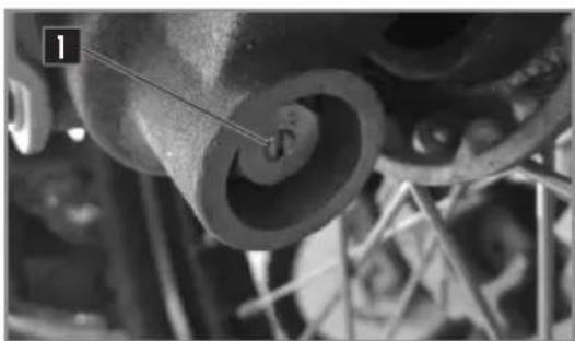
The adjusting screws 1 determine the behavior of the fork when it rebounds. Turning the screws clockwise increases the hydraulic force (and vice versa).
The adjustment screws 1 are located at the end of the lower fork legs.
Turn the screw 1 clockwise to the stop then go back the number of clicks required.
| Setting rebound KAYABA (Racing) | Comfort | 18 clicks |
| Standard | 12 clicks | |
| Sport | 10 clicks | |
| Setting rebound KAYABA (Factory) | Comfort | 14 clicks |
| Standard | 12 clicks | |
| Sport | 10 clicks | |
ADJUSTING THE REAR SHOCK LOW-SPEED COMPRESSION SETTING
natural_image
Close-up of a vehicle's air duct system with labeled components (no readable text or symbols)KAYABA
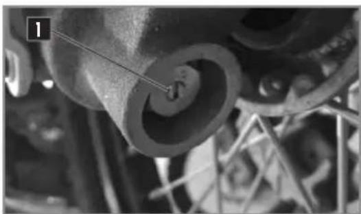
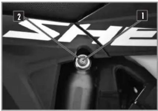
The adjusting screw 1 determines the slow speed behavior of the rear shock (sensitivity Turning the screw clockwise increases the hydraulic force (and vice versa).
Turn the screw 1 clockwise with a screwdriver until it stops and then turn it back the number of clicks required.
Do not loosen the nut 2.
REAR SHOCK KAYABA
| Low-speed compression setting | Comfort | 20 clicks |
| Standard | 14 clicks | |
| Sport | 12 clicks |
ADJUSTING THE REAR SHOCK HIGH-SPEED COMPRESSION SETTING
text_image
SHEKAYABA
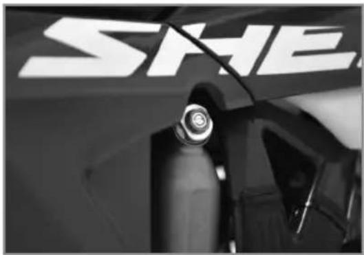
The adjusting nut 2 determines the high speed behaviour of the rear shock (big hits). Turning the screw clockwise increases the hydraulic force (and vice versa).
Turn the nut 2 clockwise with a socket wrench until it stops and then back the number of clicks required.
Do not loosen the screw 1.
REAR SHOCK KAYABA
| High-speed compression setting | Comfort | 2,5 turns |
| Standard | 1,5 turns | |
| Sport | 1 turn |
REBOUND DAMPER
natural_image
Close-up of mechanical components with no visible text or symbolsSETTING THE REAR SHOCK SAG
text_image
R1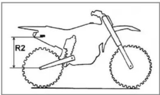
text_image
R2SETTING THE RIDING SAG
natural_image
Silhouette of a person riding a dirt bike with visible tire tracks and a labeled radius R3 (no text or symbols beyond the label)The adjusting screw 1 determines the Shock rebound behavior. Turning the screw clockwise increases the hydraulic force (and vice versa).
Turn the screw 1 clockwise to the stop then go back the number of clicks required.
REAR SHOCK KAYABA
| Rebound damping | Comfort | 15 clicks |
| Standard | 13 clicks | |
| Sport | 11 clicks |
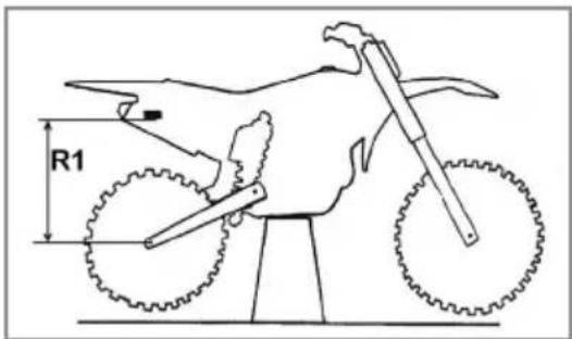
With the bike on an appropriate stand
Measure the dimension R1 between a fixed point on the chassis and the rear axle.
With the bike setting on its wheels
Measure the dimension R2 from the same fixed point on the chassis and the rear axle. The static deflection is the difference between R1-R2.
| Static deflection | 35mm-40mm |
If the static deflection is not correct, adjust the preload of the shock (p.115).
With the rider on the motorcycle
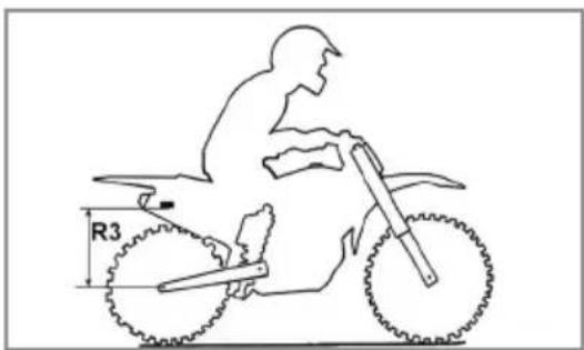
Measure the dimension R3 between the same fixed point on the chassis and the rear axle.
The sag is the difference between R1-R3.
| Sag | 95mm-100mm |
If the sag is not correct, change the spring (p.115).
REAR SHOCK KAYABA
text_image
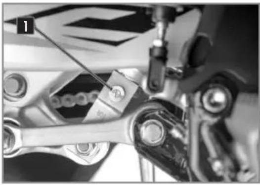
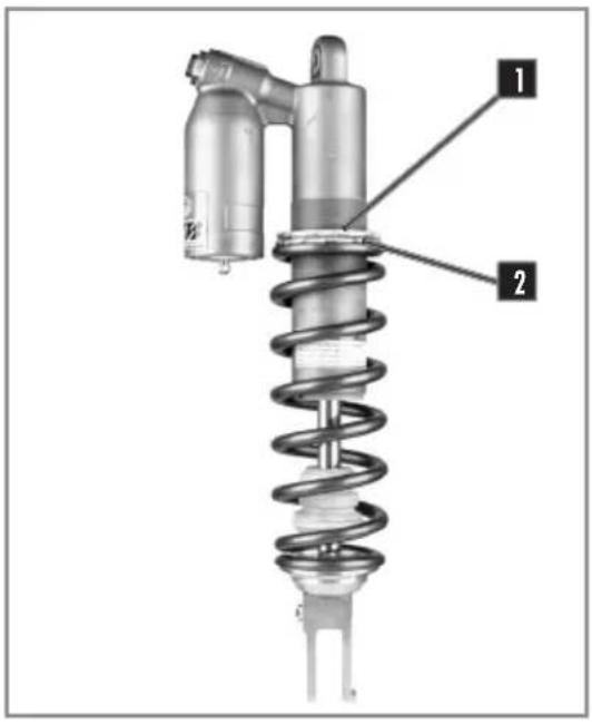
Technical diagram of a mechanical spring assembly with labeled parts 1 and 2- Remove and clean the rear shock unit (p.124). Loosen the collar 1.
Loosen / tighten the red plastic ring 2 depending on the length required.
| Indications | Loosening one turn | Decreases the overall length by 4mm. |
| Tightening one turn | Increases the overall length by 4mm. |
- Tighten the collar 1.
- Reinstall the shock (p.124)
- Recheck the settings (p.113)
CHANGING THE SHOCK SPRING
natural_image
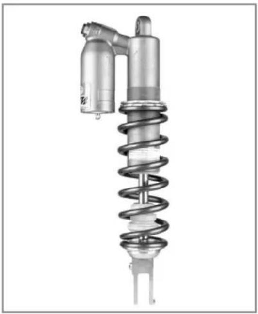
Mechanical component with coiled spring and cylindrical housing (no visible text or symbols)- Remove and clean the rear shock unit (p.124).
-
Select and install a spring based on your weight.
-
Reinstall the shock.
- Adjust the sag (p.114).
-- Adjust the riding sag (p.114).
| Spring Rate | KAYABA |
| Rider Weight (with equipment): 65-75kg | 44N/mm |
| Rider Weight (with equipment): 75-85kg | 46N/mm |
| Rider Weight (with equipment): 85-95kg | 48N/mm |
CHASSIS MAINTENANCE
REMOVING THE SEAT
text_image
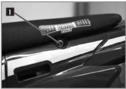
1 COTIE DIANA VILLI ITALYUnscrew the fixing screw 1 on each side of the seat.
Remove the seat by pulling it towards the back of the bike.
REINSTALLING OF THE SEAT
natural_image
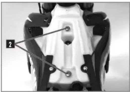
Top-down view of a motorcycle's front wheel and side brackets (no text or symbols visible)Replace the seat, ensuring that it is correctly fitted into the tank pads 2.
Replace the fixing screws 1.
REMOVING THE AIR FILTER

natural_image
Close-up of a hand adjusting a vehicle's wheel and gear assembly (no visible text or symbols)The air filter is vital for the smooth operation of your engine. Maintenance is therefore essential.
A dirty air filter reduces the performance of your bike, increases fuel consumption and, at worst, impurities can pass into the engine and cause premature wear.
natural_image
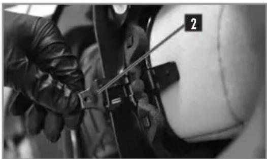
Close-up of gloved hands using a tool to adjust or install a mechanical component (no visible text or symbols)Remove the side panel 1 by pulling outwards.
Unlock the tab 2 and take out the filter.
Separate the filter from its plastic holder.
CHASSIS MAINTENANCE
CLEANING THE AIR FILTER
Clean the foam air filter with a special liquid cleaner and let dry.
i INFO
Do not clean the air filter with a solvent or gasoline.
| Air filter cleaner | Motorex® Air Filter Cleaner |
i INFO
Do not wring out the filter by twisting. Press only. Soak the air filter in an air filter oil.
| Air Filter oil | Motorex® Air Filter Oil |
If necessary clean the inside of the air box with a cloth.
REINSTALLING THE AIR FILTER
natural_image
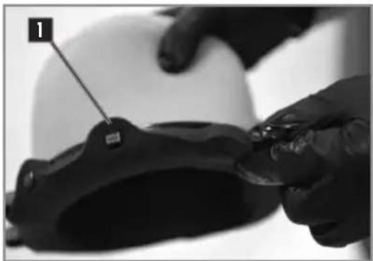
Close-up of hands adjusting a black helmet component with a numbered label (1) pointing to the part, against a white background.Reposition the filter on its support.
Be sure to engage on all six tabs 1.
Apply a film of grease on the face of the filter element.
natural_image
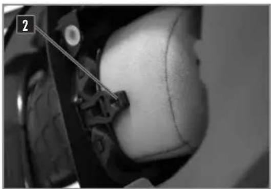
Close-up of a person's lower face and neck with a medical device attached, no visible text or symbolsReinstall the filter and its support by taking special care to make sure it is centered.
Replace the tab 2.
Check to make sure the air filter is properly seated.
CHASSIS MAINTENANCE
REMOVING THE FUEL TANK
text_image
2 1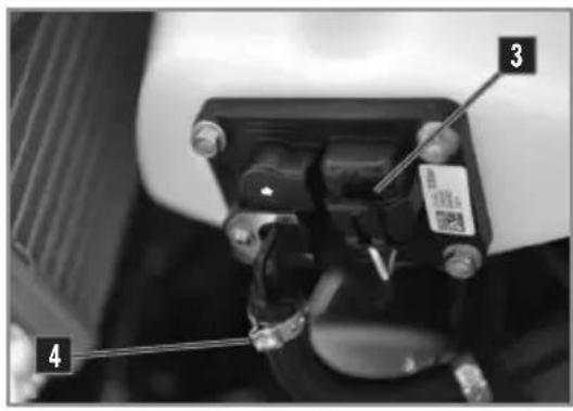
text_image
Close-up of a mechanical component with numbered parts labeled 3 and 4, showing a screwdriver inserted into a housing.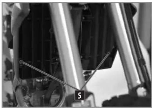
natural_image
Close-up of mechanical components with visible springs and shafts, no text or symbols presentRemove the seat (p116).
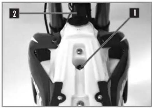
Unscrew the fuel tank fixing screws 1.
Remove the fuel tank breather hose 2.
Disconnect the fuel pump electrical connector 3.
Disconnect the hose 4 using the quick connector.
Prevent ingress of dirt in the gasoline fuel line.
This can lead to a seizure of the injector.
Unscrew the screws 5 on the right and left radiator panel.
Remove the fuel tank by pulling upwards, provide lateral clearance by slightly moving the radiator panelss. Use caution when removing the fuel tank and do not damage any of the fuel hoses or electrical connections.
! WARNING
Warning: risk of petrol splashing. Do not put your face in line with the pump's fuel outlet.
CHASSIS MAINTENANCE
REINSTALLING THE FUEL TANK
natural_image
Close-up of a car's front wheel and radiator assembly (no visible text or symbols)
text_image
Close-up mechanical component with numbered parts labeled 1, 2, and 3
natural_image
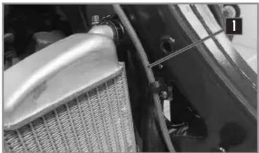
Close-up of mechanical components with visible springs and connectors (no text or symbols)Ensure proper routing of cables and hoses 1.
Install the tank by moving the radiator guards away from the radiator to provide clearance for the fuel tank and make sure that all of the cables, wires and hoses are free, clear and not pinched.
Check the adjustment of the radiator guards in relationship to the fuel tank.
Connect the fuel pump wire 2 and the fuel hose 3. Install the fuel tank mounting screw along with its rubber insert.
Install the radiator side panel screws 4.
Install the fuel tank breather hose.
| Chassis screws M6 10Nm |
Reinstall the seat (p.116).
CHASSIS MAINTENANCE
PURGING THE AIR FROM THE FORKS
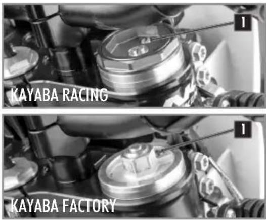
text_image
KAYABA RACING KAYABA FACTORYAfter some time of operation, the air accumulates under pressure in the fork.
Every 5 to 10 hours (depending on the riding intensity), it should be purged.
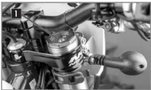
With the fork cold and fully extended, loosen and then retighten both fork screws caps 1.
CLEANING THE FORK DUST SEALS
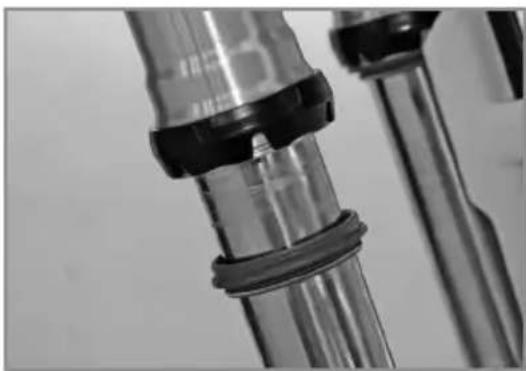
natural_image
Close-up of mechanical components with black caps and blue fittings (no visible text or symbols)Place the motorcycle on a suitable stand.
Remove the front wheel (p.125).
Remove the fork protectors. Slide the dust cover down.
Clean and lubricate the dust cover and the fork tube.
Motorex® Bike Grease 2000
Reinstall the dust cover and clean off any left over oil.
Reinstall the fork protection.
Reinstall the front wheel (p.125).
Take the bike off of the stand.
CHECKING THE PLAY OF THE STEERING HEAD BEARINGS
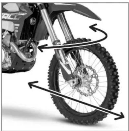
natural_image
Close-up of a motor dork wheel and tire assembly with motion arrows indicating rotational direction (no text or symbols)Place the motorcycle on a suitable stand.
Exert a back and forth force on the fork legs.
There should not be any play in the bearings in any direction in the steering bearings.
If there is play and / or resistance, adjust and / or change the bearings.
Adjust the bearing free play (p.121).
Take the bike off of the stand.
RÉGLAGE DU JEU DES ROULEMENTS DE DIRECTION
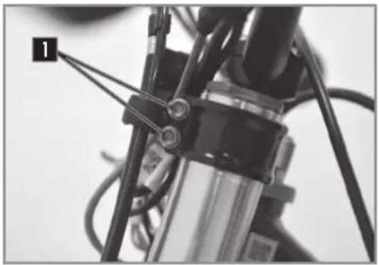
natural_image
Close-up of a mechanical assembly with wires and a labeled component (no readable text or symbols)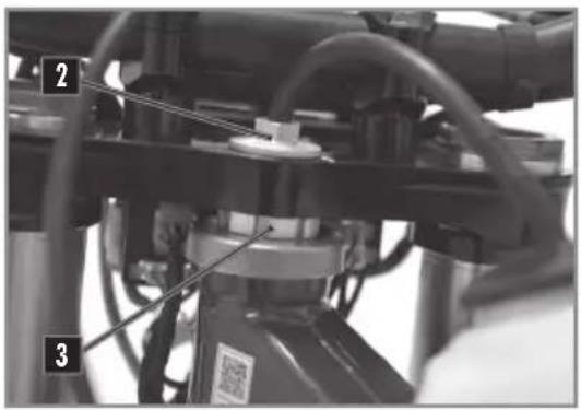
text_image
Technical diagram of a mechanical assembly with numbered components and labeled partsCLEANING THE CHAIN
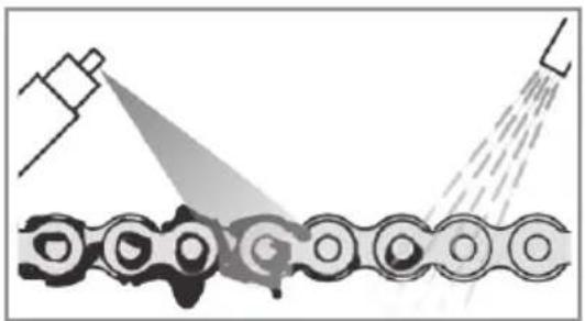
natural_image
Diagram showing a mechanical assembly with spray gun spraying through a chain (no text or symbols)CHECKING THE CHAIN TENSION
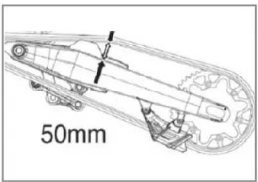
text_image
50mmMoto sur trépied.
Desserrer les vis 1.
Desserer la vis de colonne de direction 2.
| Vis de direction | M20 | 30Nm |
Regularly cleaning the chain considerably increases its service life.
Clean the chain and apply chain lubricant.
| Chain Cleaner | Motorex ^ Chain Clean Degreaser |
| Chain grease | Motorex ^ ChainLube OffRoad |
Place the motorcycle on a suitable stand.
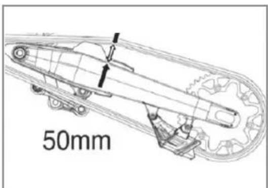
Push the chain up and measure the chain movement as shown in the diagram.
| Chain tension | 50mm...53mm |
If the chain tension is not correct, see how to adjust the chain (p.122).
Otherwise, remove the bike from the stand.
CHASSIS MAINTENANCE
ADJUSTING THE CHAIN TENSION
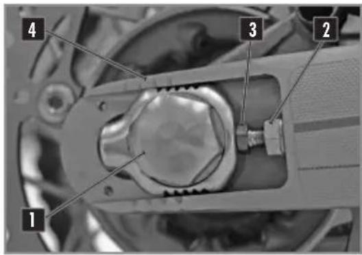
text_image
1 2 3 4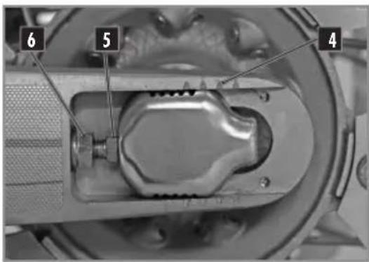
text_image
6 5 4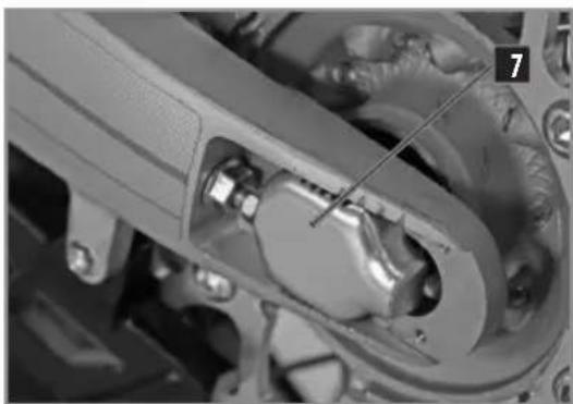
natural_image
Close-up mechanical assembly showing a clamping mechanism with no visible text or symbolsImproper chain tension can cause mechanical damage.
Place the motorcycle on a suitable stand.
Loosen nut 1.
Loosen the nuts 2.
Loosen or tighten the screws 3 until you have the correct chain tension.
Chain tension 50mm...53mm
Monitor the symmetry of the two sides by observing the position of the marks 4.
Tighten the screws 5.
Tighten the nut 6.
Rear axle nut M24 100Nm
Remove the bike from the stand.

NOTE
The sliding piece 7 is designed to accommodate longer chains by turning it 180 degrees.
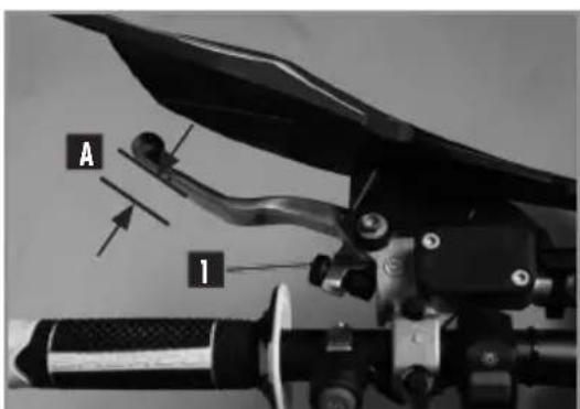
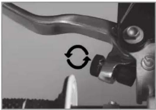
The position of the lever can be adjusted to meet the needs of the rider.
- Turn the knob 1 clockwise to move the lever closer to the handlebar.
CHASSIS MAINTENANCE
natural_image
Close-up of a mechanical lever handle with circular arrow indicating cycle (no text or symbols)CHECKING THE CLUTCH FLUID LEVEL
text_image
1 2 3- Turn the knob 1 in the opposite direction to move the lever away from the handlebar.
Clutch lever free play A ≥3mm

WARNING
- The hydraulic fluid is highly corrosive it can be dangerous to the skin.
- Read the recommendations on the container.
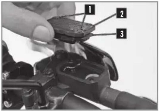
Position the master cylinder horizontally.
- Remove the two screws 1, the cover 2 and the membrane 3.
- Check the fluid level and fill if necessary.
Level of brake fluid below the top of the reservoir.
4mm
Motorex® Brake Fluid Dot 4
- Reinstall the lid with the membrane and the screws.
CHASSIS MAINTENANCE
DÉMONTAGE DE L'AMORTISSEUR
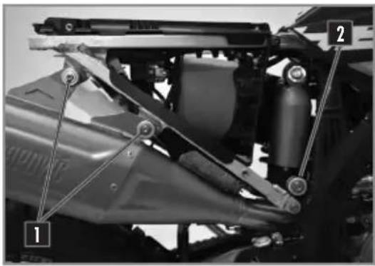
natural_image
Mechanical assembly diagram showing a vehicle's suspension system with labeled components (no readable text or symbols)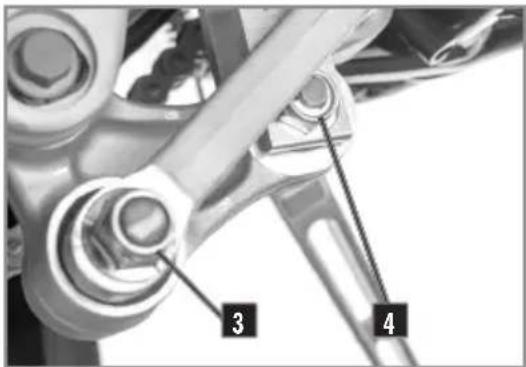
text_image
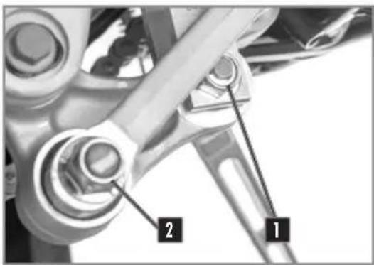
3 4REMONTAGE DE L'AMORTISSEUR
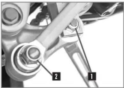
natural_image
Close-up of mechanical components with numbered annotations (1 and 2), no readable text or symbols beyond labels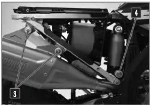
text_image
Technical diagram of a vehicle's suspension system with numbered components labeled 3 and 4Moto sur trépied.
natural_image
Close-up of mechanical components with numbered labels (1 and 2) pointing to features, no readable text or symbols beyond labels.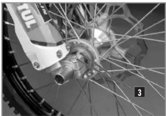
natural_image
Close-up of a bicycle wheel with visible tire, hub, and spokes (no text or symbols)REINSTALLING THE FRONT WHEEL
text_image
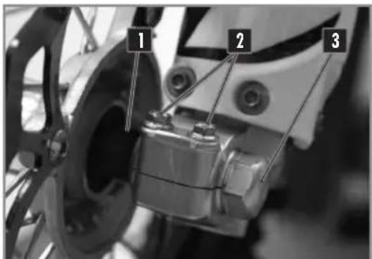
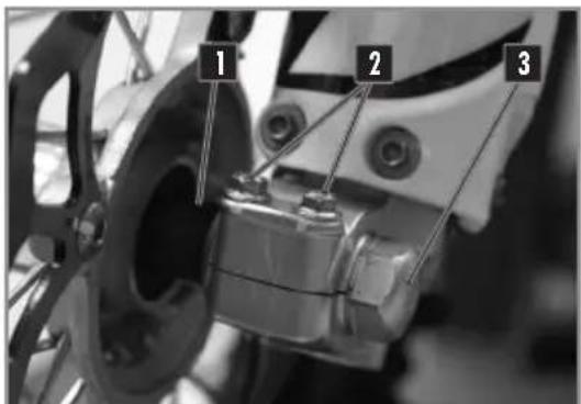
1 2 3Place the motorcycle on a suitable stand.
Remove the two screws 1 and the nut 2.
Loosen the two screws 3.
Pull the axle through the right side.
Remove the wheel from the fork.

WARNING
Do not operate the front brake lever when the front wheel is removed.
Check if the brake disc is not dirty or contaminated with oil or grease. If it is, clean the disc with brake cleaner.
Motorex® Brake CleanBrake clean
Install the spacer 1 on the left side of the wheel hub. Install the front wheel in the fork and install the axle (grease the axle prior to installation).
Tighten the screws 2.
| Fork screws | M8 | 15Nm |
Install and tighten the axle nut 3.
| Front wheel axle nut | M20 | 60Nm |
Tighten the screws on the right side of the bike.
| Fork leg screws | M8 | 15Nm |
Loosen screws 2
Actuate the front brake lever several times until the brake pads touch the disc.
Remove the motorbike from the stand and push the fork several times.
Tighten the 2 screws 2 .
WHEELS, TIRES
REMOVING THE REAR WHEEL
natural_image
Close-up of hands installing a mechanical component with labeled parts (1 and 2), no visible text or symbols beyond labels.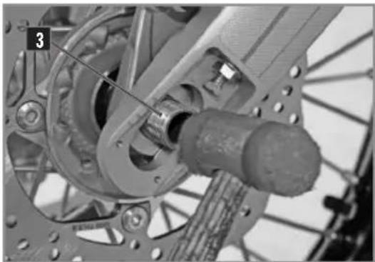
natural_image
Mechanical assembly diagram showing a motor and gear assembly with no visible text or symbolsPlace the motorcycle on a suitable stand.
- Loosen the nut 1 and remove the adjuster 2.
- Tap the axle 3 out using a nylon hammer.
- Remove the axle.
- Move the wheel as far forward as possible.
- Remove the chain and wheel.
WARNING
Do not operate the rear brake pedal when the rear wheel is removed.
REINSTALLING THE REAR WHEEL
natural_image
Close-up of a bicycle wheel with visible gear and hub structure (no text or symbols)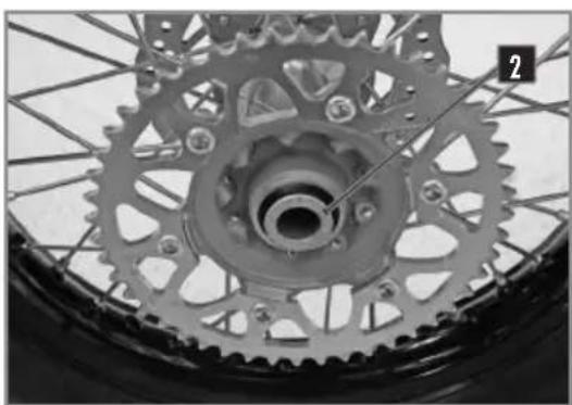
natural_image
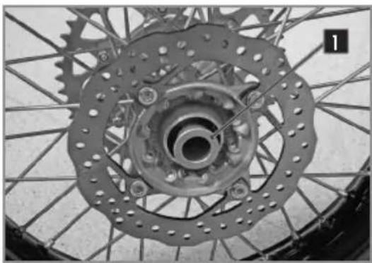
Close-up of a bicycle wheel with visible gears and hub, no text or symbols presentCheck if the brake disc is not dirty or contaminated with oil or grease.
If it is, clean the disc with brake cleaner.
Motorex® Brake CleanBrake cleaner
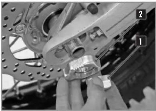
Install the two spacers 1 and 2 and make sure they are positioned correctly.
natural_image
Close-up of a motorcycle wheel with visible tire, chain, and gear (no text or symbols)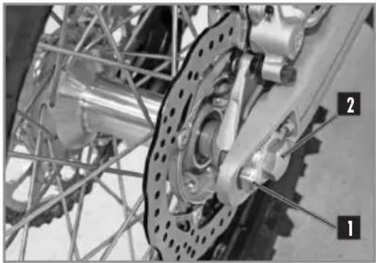
natural_image
Close-up of bicycle wheel assembly with visible components and wiring (no text or symbols)CHECKING THE TIRE PRESSURE
natural_image
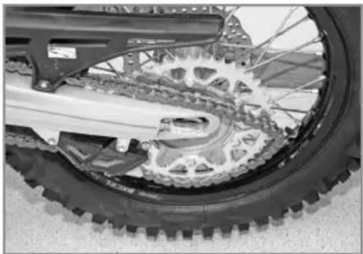
Close-up of a bicycle tire with a pressure gauge and cable, no visible text or symbolsInstall the rear wheel in the swing arm and install the axle (grease the axle prior to installation). Mount the chain.
Install the chain tensioner 1 and install the nut 2 but do not tighten.
Check the chain tension (p.122).
Tighten the nut 2.
| Rear axle nut M24 100Nm |
Operate the rear brake pedal several times until the pads touch the disk.
Remove the bike from the stand.
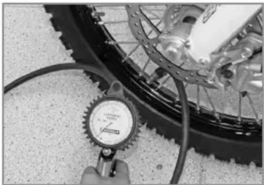
Regularly check the tire pressure with a precision pressure gauge.
- Remove the valve cap.
- Check air pressure when the tire is cold.
Tire air pressure when used in rough terrain.
| Front | 0,9bar (13 psi) |
| Rear | 0,9bar (13 psi) |
If the pressure does not comply with the above table:
- Correct the pressure.
- Replace the valve cap.
WHEELS, TIRES
CHECKING FOR WEAR AND DAMAGE
- Regularly check the depth of the tread.
Tread depth ≥ 3mm
If the depth is less than the value shown:
- Change the tire.
Check for cuts, cracks, nails, sharp objects and bulges on the tire.
If the tire is damaged:
- Change the tire.
CHECKING SPOKE TENSION
natural_image
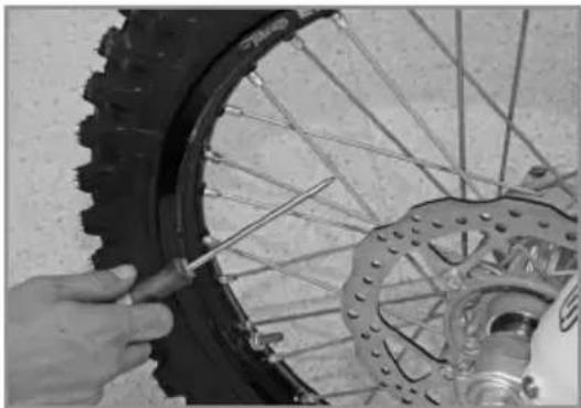
Close-up of hands using a screwdriver to adjust the wheel rim of a bicycle tire (no text or symbols visible)Do not neglect the tension of the spokes.
! WARNING
Proper tension ensures stability and secure riding.
- Check the spoke tension before and after each use of the bike, especially if the spokes are new or have been recently adjusted.
- Use a screwdriver to tap on each spoke.
The sound must be sharp. - If it is dull, take the bike to a Sherco dealer to get the spokes properly adjusted.
Indicative tightening torque 5 - 6 Nm
BRAKES
natural_image
Close-up of a bicycle brake lever with labeled component A (no text or symbols beyond label)Pull the lever toward the handlebar and check the free play A.
Free play of the front brake lever ≥3mm
If the free play does not meet the specification, do the following.
natural_image
Close-up of a bicycle brake lever mechanism with handle and grip (no visible text or symbols)Set the free play using the adjustment screw 1.
- Turn clockwise to decrease the free play.
- Turn it counterclockwise to increase the free play.
natural_image
Close-up of a small electronic device with a lens and black casing, partially visible against a blurred background (no text or symbols)Make sure that the reservoir is in a horizontal position. Check the fluid level through the sight glass.
Ensure that the level is (between the arrows) it should be closest to the up arrow.

If the level is below the MIN mark, top up the brake fluid according to the instructions below.
- The hydraulic fluid is highly corrosive.
- It can be dangerous to the skin.
- Read the recommendations on the container.
- Remove the two screws 1.
Remove the cover 2 and the membrane 3.
Fill the tank with brake fluid to the correct level A.
| Level of brake fluid below the top of the reservoir. | 5mm |
| Motorex® Brake Fluid Dot 4 | |
- Reinstall the membrane, the cover and the screws.
natural_image
Close-up mechanical assembly showing two labeled parts (1 and 2) with no visible text or symbolsThe position of the brake pedal can be adjusted as follows: loosen the lock nut 1 loosen or tighten the screw 2 to obtain the desired position.
Tighten the lock nut when the pedal is properly located.
| Brake pedal lock nut | 10NmM6 |
Check the pedal travel ( below).
CHECKING THE TRAVEL OF THE REAR BRAKE PEDAL
text_image
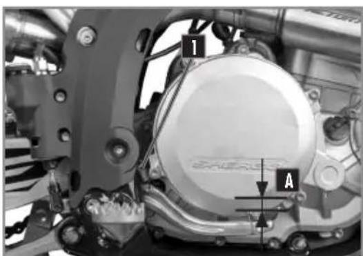
1 A- Remove the spring 1.
- Operate the pedal several times.
Rear brake pedal travel ≥3mm A ≥5mm
- Replace the spring 1.
If the travel does not meet the specification, refer to the rear brake travel adjustment.(p.135).
BRAKES
ADJUSTING THE TRAVEL OF THE REAR BRAKE PEDAL
text_image
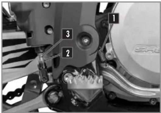
1 2 3- Remove the spring 1. - Loosen the nut 2 and turn the shaft 3.
Rear brake pedal travel ≥3mm A ≥5mm
Hold the shaft 3 and tighten the nut 2.
Nut 10Nm
natural_image
Close-up of a mechanical component with a cylindrical housing and mounting holes (no visible text or symbols)Position the motorcycle on a flat surface. Check the fluid level through the sight glass. Ensure that the level (between the arrows) is closest to the up arrow.

If the level is below the MIN mark, top up the brake fluid according to the instructions below.
Remove the cap 1 with its membrane 2. Fill with fluid to the mark as shown A.
Motorex® Brake Fluid Dot 4
- Reinstall the membrane and the cover using a new 0-ring.

natural_image
Close-up of a mechanical component with a labeled section 'A' and bolted base (no readable text or symbols beyond label)BRAKES
REMOVING THE FRONT AND REAR BRAKE PADS
text_image
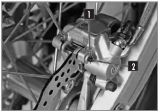
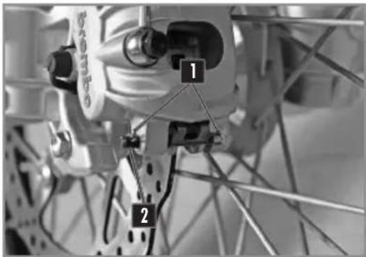
Technical diagram of a mechanical assembly with numbered components labeled 1 and 2- Remove the clip 1 and retaining pin 2.
- Remove the brake pads.
Do not operate the front brake lever or rear brake pedal when the brake pads are removed.
text_image
Labeled mechanical component diagram showing two numbered parts with connecting rods and structural connectionsCHECKING THE CONDITION OF THE BRAKE PADS
natural_image
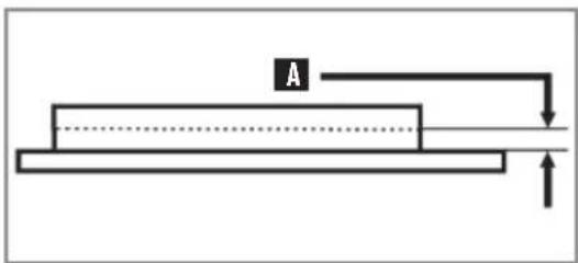
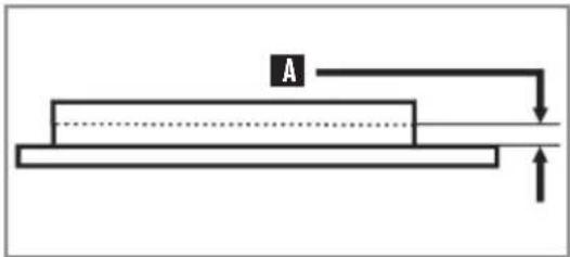
Simple line diagram of a rectangular object with an arrow labeled 'A' and a horizontal line, no text or symbols present.Check the pads for wear.
Minimum pad thickness A ≥1mm
If replacement is necessary, always change the pads in pairs.
REINSTALLING THE FRONT AND REAR BRAKE PADS
text_image
Technical diagram of a mechanical assembly with numbered components labeled 1 and 2Check if the brake discs are not contaminated with oil or grease. In they are, clean the discs with brake cleaner.
Brake cleaner Motorex® Brake Clean
BRAKES
text_image
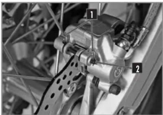
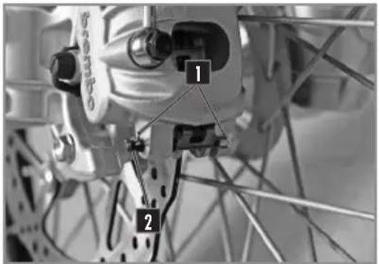
Close-up mechanical component with numbered labels 1 and 2 indicating parts of a bicycle or suspension system.Install the new pads.
Reinstall the retaining pins 2 and clips 1.
Check the brake fluid level and fill if necessary (p.129 and p.131).
CAUTION
Do not use the bike until the brake lever and the pedal are operational. «Pump» the brake lever / brake pedal up and down until the brake pads are in contact with the discs.
text_image
Close-up of a mechanical component with numbered annotations pointing to parts 2 and 3Turn off all electric devices and stop the engine.
CAUTION
WAIT AT LEAST 30 SECONDES BIKE TURNED OFF AND STOPPED SO THAT THE KEYLESS SYSTEM TURNS OFF. IF THIS IS NOT DONE THERE IS A SIGNIFICANT RISK OF DAMAGE TO THE COMPUTER (ECU)

natural_image
Close-up of a mechanical component with wires and a small display panel (no visible text or symbols)- Remove the seat (p.116).
The battery is located at the bottom of the filter housing.
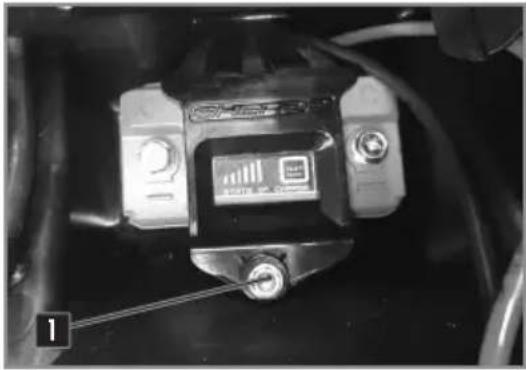
- Remove the two screws 1 that retain the battery retaining bracket.
- Disconnect the negative cable from the battery 2.
- Disconnect the battery positive cable 3.
- Remove the battery from the top.
REINSTALLING THE BATTERY
natural_image
Close-up of a mechanical component with no visible text or symbols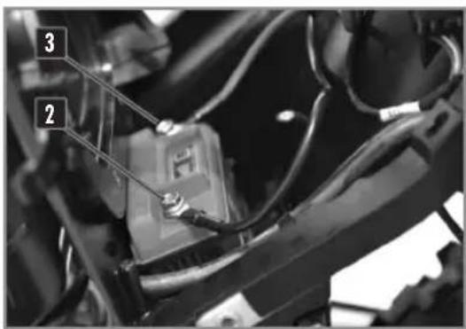
text_image
Close-up of a mechanical component with numbered annotations pointing to parts 2 and 3- Insert the battery into place.
- Tighten the screw 1.
- Connect the positive cable to the battery.
- Connect the negative cable to the battery.
Chassis screws 10NmM6
- Check the positioning of the battery cables to make sure that they do not interfere with the installation of the air filter.
- Replace the air filter (p.116).
- Replace the seat (p.116).
CHARGING THE BATTERY
The battery is a maintenance-free type. If the vehicle is not used for an extended period, it is recommended that the battery be disconnected and stored in a dry place. See removing the battery (p.133).
Check the voltage of the battery with a voltmeter:
Battery voltage
12.5V
If battery voltage is too low, remove the battery from the bike and charge it using a special chager suited to lithium batteries.
Disconnect the charger after charging. Install the battery ( above).
REPLACING THE MAIN FUSE
natural_image
Close-up of a car's engine compartment with visible wiring and a numbered component (no text or symbols)Remove the right side panel.
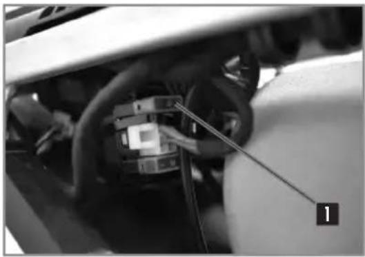
The main fuse 1 is on a relay by the starter.
Remove the defective fuse and replace with a new fuse of the same value.
| Main fuse | 30A |
Put a new spare fuse in the reserve location in the fuse box.
REPLACING THE FUSE FOR THE LIGHTS
natural_image
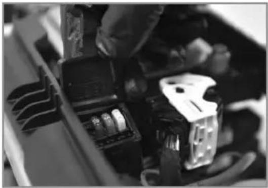
Close-up of a hand installing or adjusting electronic components in a device (no visible text or symbols)Remove the seat (p. 116).
The fuse is in the fuse box located on the top of the subframe.
Remove the defective fuse and replace with a new fuse of the same value.
| Light fuse | 15A |
- Replace the seat (p.116).
REMOVING THE HEADLIGHT HOUSING
natural_image
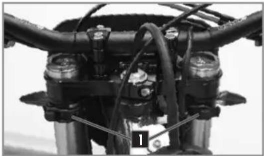
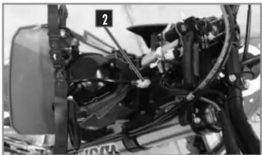
Close-up of a motorcycle's front wheel and drivetrain components (no visible text or symbols)Turn the ignition to the off position.
Unclip the left and right rubber fastners 1 on each side of the fork.
Separate all of the brake hoses / cables from the meter bracket at the top and bottom.
Move the top plate up to clear the housing.
Disconnect the connector 2 and remove the headlight housing.
natural_image
Close-up of a mechanical assembly with visible components and wiring (no text or symbols)natural_image
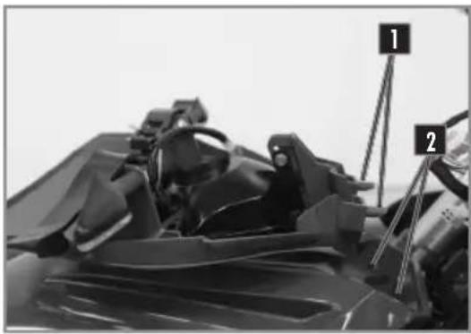
Close-up of a mechanical component with numbered parts (1 and 2) and no visible text or symbolsConnect the electrical connector.
Engage the headlight housing making sure the pins 1 fit into the holes 2 in the front mudguard.
natural_image
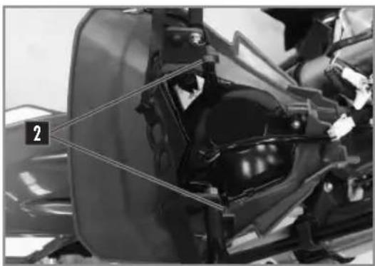
Close-up of a motorcycle's front wheel and side seat assembly (no visible text or symbols)The front light unit is sealed with LEDs.
If one or more LEDs burn out, the entire unit must be replaced.
For light unit change, remove the screw 1 and spread the brackets 2.
natural_image
Close-up of a mechanical component with labeled part '2' (no visible text or symbols)natural_image
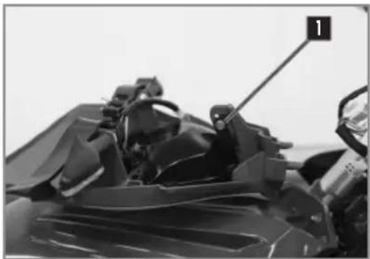
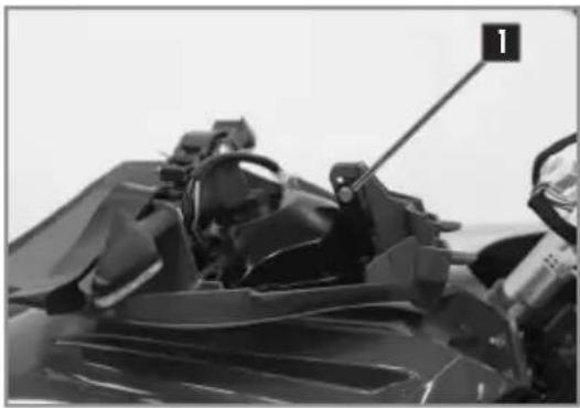
Close-up of a motorcycle's seat frame with visible structural components and a numbered label (1) pointing to the handle.The headlight beam is adjusted with the motorcycle in running order with its driver seated on the saddle.
To set headlight beam, loosen screw 1.
REPLACING THE MOTORCYCLE COMPUTER BATTERY
natural_image
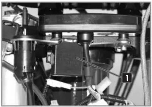
Close-up of mechanical components with wires and a labeled component (no readable text or symbols)- Remove the headlight housing (p.135).
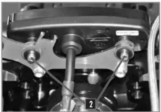
- Remove the turn 1 signal flasher in order to access the motorcycle computer screws.
- Remove the screws 2 and remove the computer to get it out of the way.
- Disconnect the main connector from the computer.
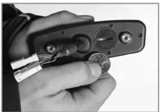
- Open the dashbord with a coin.
- Install a new battery (with the marking up).
Computer battery CR 2032 3V
natural_image
Close-up mechanical assembly showing internal components and a numbered label (2), no readable text or symbols present.- Replace the cover, taking care not to damage the O-ring.
- Plug the main connector into the computer.
- Install it on the bike and check to make sure the meter works.
- Reinstall the computer support.
- Install screws 2 and replace the turn signal flasher.
- Replace the headlight housing (p.136).
- Set the computer (p.99).
natural_image
Close-up of a hand holding a handheld electronic device with wires and a coin, no visible text or symbols.WASHING THE BIKE STORING THE BIKE
SHERCO advises you to wash your bike as often as possible in order to maintain it in good working order and prolong its life.
- Cover the end of the exhaust silencer and the air filter (to cover the exhaust outlet use part number 8527, to cover the air intake use part number 4476).
- To degrease the engine, apply a degreaser, clean with a brush then rinse the engine with a water hose.
- Wash the rest of the vehicle with hot soapy water.
- Rinse with clear water.
- Dry with a chamois or a clean, soft cloth.
- Clean the chain and lubricate it with a special chain lube.
- When the cleaning is finished, remove the air filter and exhaust protection, Start the engine and let it run atidle for a few minutes.
Avoid using high pressure equipment which may cause water to leak into the bearings and fork seals and cause serious damage.
Use an average strength detergent rather than a strong detergent.
CAUTION
In order to avoid any water ingress, keep a minimal washing distance of 20cm.
Before storing the vehicle Long-Term (more than 2 months), follow these instructions:
- Wash the whole bike.
- Empty the fuel tank.
- Remove the spark plug and inject a protective spray inside the engine through the hole in the cylinder. Install the spark plug. Cycle the engine a few revolutions to apply a protective film on the cylinder walls.
- Remove the battery (p.133).
- Charge the battery (p.134).
- Lubricate all cables with a spray lubricant.
- Jack the motorcycle up so that the wheels are off the ground.
- Cover the exhaust outlet with a plastic bag to prevent moisture from entering.
- Spray a protective oil film on all unpainted metal surfaces of the motor and also on the electrical wiring.
- Cover the motorcycle with a cover.
RECOMMISSIONING AFTER STORAGE
Reinstall the battery (p.134).
Fill the fuel tank.
Perform lubrication and maintenance (p.139)
Perform a road test.
MAINTENANCE SCHEDULE
| MAINTENANCE | After 5 hours | Every 20 hours |
| ENGINE | ||
| Change engine oil, filter, clean pre filter and change if necessary | ● | ● |
| Clean the magnetic drain plug | ● | ● |
| Replace spark plug (after 50 hours) | ||
| Check and adjust valve clearances | ● | ● |
| Check engine mounting bolts for tightness | ● | ● |
| INJECTION | ||
| Clean the venturi | ● | |
| ACCESSORIES | ||
| Check cooling system for leaks | ● | ● |
| Check sealing and attachment of the exhaust | ● | ● |
| Check status, flexibility and position of the cables, adjust and lubricate | ● | ● |
| Check oil level in clutch master cylinder | ● | ● |
| Clean air filter and housing | ● | ● |
| Check status and position of the electrical wiring | ||
| Check function of electric components (headlight/tail/stop turn signals, computer control unit, etc.) | ● | ● |
| BRAKES | ||
| Check brake fluid level, brake pad thickness and the brake discs | ● | ● |
| Check status and sealing of the brake lines | ● | ● |
| Check status, of the foot brake pedal and hand brake lever | ● | ● |
| Check tightness of brake system fastners and discs | ● | ● |
| CHASSIS | ||
| Check for leaks and function of fork and shock | ● | ● |
| Clean the dust covers | ● | ● |
| Purge air from the fork legs | ● | ● |
| Check general tightness of bolts and screws | ● | ● |
| Check / adjust steering head bearings | ● | ● |
| WHEELS | ||
| Check rims and spoke tension | ● | ● |
| Check condition of the tires and tire pressure | ● | ● |
| Check chain, sprockets, guides, chain tension | ● | ● |
| Lubricate the chain | ● | ● |
| Check wheel bearing clearance | ● | ● |
MAINTENANCE SCHEDULE
ANNUAL MAINTENANCE
| MAJOR MAINTENANCE ITEMS THAT SHOULD BE PERFORMED BY THE DEALER | Au moins 1X par an |
| Fork | ● |
| Shock | ● |
| Clean and grease steering head bearings and seals | ● |
| Replace fiberglass in the muffler | ● |
| Treat electric contacts and switches with an aerosol protector | ● |
| Replace the brake fluid | ● |
| CHECKS AND MAJOR MAINTENANCE TO BE PERFORMED BY THE RIDER | Before each use | After each use |
| Check the engine oil level | ● | |
| Check brake fluid level | ● | |
| Check status of the brake pads | ● | |
| Verify operation of the lights | ● | |
| Verify operation of the horn | ● | |
| Lubricate throttle cable | ● | |
| Regularly purge the air from the fork legs | ● | |
| Regularly clean the fork dust seals | ● | |
| Clean and lubricate chain, check tension and adjust if necessary | ● | |
| Clean air filter and box | ● | |
| Check tires and tire pressure | ● | |
| Check the coolant level | ● | |
| Check fuel lines for leaks | ● | |
| Check status of all the controls | ● | |
| Check the brakes | ● | ● |
| Spray anti-corrosion protector on all non painted parts (except for the brake parts and the exhaust system) | ● | |
| Spray protector on electrical switches | ● | |
| Check tightness of nuts, screws and clamps | ● |

WARNING
Check the tightening of the screws of your bike after the first ride / the first hours of use.
In competition you have to perform the 20 hour maintenance schedule after each race!
This should not be exceeded by more than 2 hours.
The services performed by the Sherco dealer do not replace routine service and maintenance by the rider!
MAINTENANCE SCHEDULE
IMPORTANT CHECKS AND MAJOR MAINTENANCE ITEMS THAT SHOULD BE PERFORMED BY THE DEALER
| Competition use | At 50HAt | 20H 100H | |
| Recreational use | At 50H | At 100H | |
| Check the clutch disc wear | ● | ● | ● |
| Check the length of the clutch springs | ● | ● | ● |
| Check that the clutch nut is not loose | ● | ● | |
| Check that the clutch housing is not loose | ● | ● | |
| Check that the wear of the cylinder and piston | ● | ● | |
| Replace the piston | ● | ● | |
| Check the camshafts for wear (a) visually check | ● | ● | |
| Check the camshaft buckets for wear | ● | ● | |
| Check the wear of valve guides | ● | ● | |
| Replace the valve | ● | ||
| Replace the valve springs | ● | ||
| Check operation of chain tensioner guide | ● | ● | |
| Check the run-out at the end of the crankshaft | ● | ● | |
| Check the condition of the connecting rod | ● | ● | |
| Check the big en bearing | ● | ● | ● |
| Replace the crankshaft bearing | ● | ● | |
| Check all of the gearbox components for wear | ● | ● | |
| Check ECU's errors with the Sherco diagnostic tool | ● | ● | ● |
| Check and charge the battery | ● | ● | ● |
| Check the fuel pressure | ● | ● | ● |
| Check the oil pump | ● | ● | ● |
| Check the length of the relief valve spring | ● | ● | |
| Replace fiberglass packing in the muffler | ● | ● | ● |
| Check the length of the camshaft drive chain | ● | ● | |
| Check the camshaft bearings | ● |
MAINTENANCE SCHEDULE
IMPORTANT CHECKS AND MAINTENANCE WORK TO BE CARRIED OUT BY A SHERCO WORKSHOP
| Sand competition use | Every race | Every 20hours | Every 30hours | Every 50hours |
| Check the clutch discs for wear | ● | ● | ||
| Check the length of the clutch springs | ● | ● | ||
| Check that the clutch nut is not marked | ● | |||
| Check that the clutch bell is not marked | ● | |||
| Check the wear of the cylinder | ● | |||
| Replace the piston | ● | |||
| Check valve clearances | ● | ● | ||
| Check camshafts for wear | ● | |||
| Check the wear of the cups | ● | |||
| Check valve guides for wear | ● | |||
| Replace the valves | ● | |||
| Replace the valve springs | ● | |||
| Check the operation of the timing chain tensioner | ● | ● | ● | |
| Check the run-out at the end of the crankshaft | ● | ● | ● | |
| Replacement of the connecting rod | ● | ● | ● | |
| Replace crankshaft bearings | ● | ● | ● | |
| Check the total wear of the gearbox (sprockets, bearings, forks) | ● | ● | ||
| Replace the rock wool in the exhaust silencer | ● | |||
| Check the length of the timing chain | ● | |||
| Check the camshaft bearings | ● | |||
| Checking ECU errors with the Sherco diagnostic tool | ● | ● | ● | ● |
| Checking and charging the battery | ● | |||
| Checking the fuel pressure | ● | |||
| Checking oil pumps | ● | |||
| Injection body cleaning + stepper | ● | ● | ● | ● |
TIGHTENING TORQUES
| TIGHTENING TORQUES CYCLE PART | Dimension | Value (Nm) | Thread |
| Screw emergency stop button | M3 | 3Nm | |
| Spoke nut | M4 | 5Nm | |
| Battery screw | M4 | 7Nm | |
| Injection body cover screw | M4 | 3Nm | |
| Master cylinder cover screw | M4 | 7Nm | |
| T map sensor screw | M4 | 5Nm | |
| Odometer screw | M4 | 5Nm | Blue |
| Rear light screws | M4 | 1Nm | Blue |
| Frame protection screw | M4 | 2Nm | |
| Other frame screw | M5 | 7nm | |
| Air filter support nut | M5 | 10Nm | |
| Lever return plate | M5 | 7Nm | Blue |
| Actuator screw slows down | M5 | 8Nm | |
| Filter flap screw | M5 | 7Nm | Blue |
| TPS sensor screw | M5 | 8Nm | |
| Gas control screw | M5 | 10Nm | |
| Light switch screw | M5 | 7Nm | |
| Brake pedal end screw | M5 | 7Nm | Blue |
| Fork air bleed screw | M5 | 3Nm | |
| Regulator screw | M5 | 8Nm | Blue |
| Brake hose support screw | M5 | 7Nm | Blue |
| Injector support screw | M5 | 8Nm | Blue |
| Hand guard support screw | M5 | 10Nm | |
| Expansion tank screw | M5 | 10Nm | Blue |
| Other frame screw | M6 | 10Nm | |
| Starter cable nut | M6 | 7Nm | |
| Battery screw | M6 | 10Nm | |
| Screw Db killer | M6 | 10Nm | |
| Odometer support screw | M6 | 10Nm | Blue |
| Front mudguard screw | M6 | 12Nm | Blue |
| Chain guide screw | M6 | 12Nm | Blue |
| Skid plate bottom screw | M6 | 8Nm | Blue |
| Rear master cylinder screw | M6 | 8Nm | |
| Clutch master cylinder screw | M6 | 10Nm | |
| Front brake master cylinder screw | M6 | 10Nm | |
| Radiator side panel screw (Tank) | M6 | 3Nm | |
| Chain slider screw | M6 | 8nm | Blue |
| Chain guard screw | M6 | ||
| Fork protection screw | M6 | 8Nm | Blue |
| Chain sprocket protection screw | M6 | 12Nm | Blue |
TIGHTENING TORQUES
| Dimension | Value (Nm) | Thread | |
| Brake pedal stop adjustment screw | M6 | 8Nm | |
| Brake pedal adjustment screw | M6 | 8Nm | |
| Starter relay terminal screw | M6 | 6Nm | |
| Selector screw | M6 | 12Nm | Blue |
| Screw Flap holder | M6 | 12Nm | Blue |
| Seat lock screw | M6 | 10Nm | Blue |
| Other frame screw | M8 | 25Nm | |
| Valve nut | M8 | 8Nm | |
| Gripster nut | M8 | 12Nm | |
| Top nut rear sub frame | M8 | 25Nm | |
| Chain tensioner nut | M8 | 25Nm | |
| Handlebar flange screw | M8 | 20Nm | Cooper grease |
| Sprocket screw | M8 | 30Nm | |
| Steering stop screw | M8 | 25Nm | Blue |
| Brake disc screw | M8 | 35Nm | Red |
| Front brake calliper screw | M8 | 25Nm | Cooper grease |
| Frame chain guide screw | M8 | 25Nm | Blue |
| Bottom screw rear sub frame | M8 | 25Nm | Blue |
| Fork leg screws | M8 | 20Nm | Cooper grease |
| Steering column clamp screw | M8 | 25Nm | Cooper grease |
| Front calliper bleed screw | M8 | 10Nm | |
| Roller chain screw | M8 | 25Nm | Blue |
| Cylinder head support screw | M8 | 30Nm | Blue |
| Lower triple clamp screw | M8 | 12Nm | Cooper grease |
| Upper triple clamp screw | M8 | 17Nm | Cooper grease |
| Engine axle | M10 | 60Nm | |
| Shock absorber foot axle | M10 | 50Nm | |
| Shock absorber upper axle | M10 | 50Nm | |
| Supporting nut | M10 | 25Nm | |
| Brake hose banjo screw | M10 | 25Nm | |
| Brake pedal screw | M10 | 25Nm | |
| Handlebar clamp screw | M10 | 40Nm | Red |
| Delta link axle | M12 | 50Nm | |
| H link axle | M12 | 50nm | |
| Frame link H axle | M12 | 50Nm | |
| Screw Lambda sensor | M12 | 30Nm | |
| Swing arm axle | M16 | 100Nm | |
| Front wheel axle nut | M20 | 50Nm | Cooper grease |
| Screw nut steering column | M20 | 30Nm | |
| Rear wheel nut | M24 | 100Nm | Grease |
TIGHTENING TORQUES
| Dimension | Value (Nm) | Thread | |
| Hose guide screw | Parker | 2Nm | |
| Headlight switch screw (Racing) | Parker | 2nm | |
| Hand protector screws | Parker | 3Nm | |
| Flap support screw | Parker | 3Nm | |
| Fan screw | Auto-perforate | 3nm | |
| Clamp | 7Nm |
| TIGHTENING TORQUES ENGINE PART | Dimension | Value (Nm) | Thread |
| Engine speed sensor screw | M5 | 7Nm | Red |
| Stator screws | M5 | 7Nm | Red |
| Decompressor screw | M5 | 8Nm | Blue |
| Bearing lock plate screw | M5 | 8Nm | Blue |
| Oil collecting screw | M5 | 7Nm | Blue |
| Water pump impeller nut | M6 | 10Nm | Blue |
| Limiter shaft screw | M6 | 12Nm | Red |
| Starter pinion shaft screw | M6 | 12Nm | Red |
| Oil pump intermediate pinion shaft screw | M6 | 10Nm | Grease |
| Cylinder head cover screw | M6 | 10Nm | Grease |
| Clutch slave cylinder screw | M6 | 10Nm | Grease |
| Ignition casing screw | M6 | 10Nm | Grease |
| Clutch housing screw | M6 | 10Nm | Grease |
| Crankcase screws | M6 | 10Nm | Grease |
| Water pump cover screw | M6 | 10Nm | Grease |
| Electric starter screw | M6 | 10Nm | Grease |
| Camshaft guide plate screws | M6 | 10Nm | Blue |
| Locking finger screw selection | M6 | 10Nm | Blue |
| Oil pump cover screws | M6 | 10Nm | Blue |
| Selector star screw | M6 | 10Nm | Blue |
| External cylinder head screw | M6 | 10Nm | Blue |
| Timing tensioner shutter screw | M6 | 7Nm | |
| Distribution guide pad screw | M6 | 12Nm | Red |
| Timing tensioner pad screw | M6 | 12Nm | Red |
| Clutch spring screw | M6 | 10Nm | |
| Timing tensioner screw | M6 | 10Nm | Grease |
| Coolant drain screw | M6 | 7Nm | Grease |
| Exhaust pipe nut | M8 | 25Nm | |
| Exhaust pipe stud | M8 | 25Nm | |
| Selection shaft stop screw | M8 | 15Nm | Red |
| Camshaft bearing screw | M8 | 12Nm | Grease |
TIGHTENING TORQUES
| Dimension | Value (Nm) | Thread | |
| Top dead centre manhole cap | M10 | 10Nm | Grease |
| Spark plugs | M10 | 15Nm | Cooper grease |
| Cylinder head nut | M10 | 1er passe 15Nm2eme passe a 25Nm3eme passe a 50Nm | Grease |
| Cylinder stud | M10 | Blue | |
| Ignition nut | M12 | Blue | |
| Water temperature sensor | M12 | Yellow | |
| Oil pressure regulator | M16 | Grease | |
| Magnetic drain plug | M16 | Grease | |
| Crankshaft compartment strainer | M18 | Grease | |
| Clutch housing nut | M20 | Blue | |
| Primary gear/crankshaft nut | M20 | Blue | |
| Gearbox output sprocket nut | M20 | ||
| Water connection | M20 | Yellow | |
| Oil filter cover screw | M24 | Grease | |
| Valve shaft plug | M27 | Grease | |
| Ignition housing plug | M27 | Grease | |
| Oil suction strainer | M32 | Grease |
TECHNICAL SPECIFICATIONS 500 SUPERMOTARD
DIMENSIONS
| Overall length | 2270mm |
| Overall width | 825mm |
| Seat height | 885mm |
| Wheelbase | 1488mm |
| Ground clearance | 280mm |
CHASSIS
| Frame | Semi-perimeter CrMo steel with aluminum sub-frame |
| Fork | KAYABA USD ∅48mm Closed cartridge |
| Rear suspension | KAYABA USD ∅48mm Open cartridge |
| Travel front/rear | 300mm/300mm |
| Front brake disc | ∅310mm |
| Rear brake disc | ∅220mm |
| Disc brakes wear limit | 2.7mm front and 3.6mm rear |
| Front tire / Tire pressure | 120/70 R 17 / 2bar |
| Rear tire / Tire pressure | 150/60 R 17 / 2,2bar |
| Fuel tank capacity with reserve | 9,7 L with 1L of reserve |
| Fuel requirement | Unleaded gasoline with an octane index of at least 95d'au moins 95 |
ENGINE
| Type | Single cylinder 4 stroke liquid cooled |
| Displacement | 478,22cc |
| Bore / Stroke | 98X63,4mm |
| Compression ratio | 11.60:1 |
| Distribution | 4-valve DOHC chain drive |
| Starting System | Electric starter |
| Intake valve diameter | 38mm |
| Exhaust valve diameter | 30,5mm |
| Intake valve cold clearance | 0.15-0.2mm |
| Exhaust valve cold clearance | 0.2-0.25mm |
| Spark plug | NGK LMAR9E-J |
| Spark plug gap | 0.7 mm |
| Electronic injection | SYNERJECT |
| Alternator | 12V, 220W |
| Engine oil | 1,1L SAE 15W60 |
TECHNICAL SPECIFICATIONS 500 SUPERMOTARD
TRANSMISSION
| Type | Manual |
| Clutch | Multi disc clutch in oil bath, hydraulically operated |
| Primary drive | 25 : 68 |
| Gerarbox | 6 speeds |
| Secondary drive | 15 x 43 |
ADJUSTMENTS - KAYABA USD ∅48MM
| Compression | Comfort | 20 clicks back |
| Standard | 12 clicks back | |
| Sport | 8 clicks back | |
| Rebound | Comfort | 18 clicks back |
| Standard | 12 clicks back | |
| Sport | 10 clicks back | |
| Type of oil | KAYABA 01M | 345 CC |
ADJUSTMENTS - KAYABA SHOCK ABSORBER
| Low-speed compression | Comfort | 20 clicks back |
| Standard | 14 clicks back | |
| Sport | 12 clicks back | |
| High-speed compression | Comfort | 2,5 clicks back |
| Standard | 1,5 clicks back | |
| Sport | 1 click back | |
| Rebound | Comfort | 15 clicks back |
| Standard | 13 clicks back | |
| Sport | 11 clicks back |
CLEANING PRODUCTS AND CONSUMABLES
| Coolant | Motorex®Coolant M3.0 | |
| Brake Fluid | DOT 4 | Motorex®Brake Fluid Dot 4 |
| Fork oil | SAE 5 | |
| Shock absorber oil | KAYABA K2C | |
| Aerosol chain lube | Motorex® ChainLube OffRoad | |
| Air filter cleaner | Motorex® Air Filter Cleaner | |
| Air filter lubrican | Motorex® Air Filter Oil | |
| Plastic cleaner | Motorex®Quick Cleaner | |
| Wheel Cleaner | Motorex®Wheel Cleaner | |
| Disc brake Cleaner | Motorex®Brake Clean | |
| Universal lubricant | Motorex® Bike Grease 2000 |
MAINTENANCE SCHEDULE 500 SUPERMOTARD / DUAL SPORT
| Every year | |||||||
| After each race | |||||||
| Every 100 using hours/Every 5000kms | |||||||
| Every 50 using hours/Every 2500kms | |||||||
| Every 40 using hours/ Every 2000kms | |||||||
| Every 30 using hours / Every 1500kms | |||||||
| Every 20 using hours / Every 1000kms | |||||||
| Every 10 using hours / Every 500 kms | |||||||
| After 1 using hour | |||||||
| CHASSIS | |||||||
| Check fault code | ● | ● | ● | ● | ● | ● | ● |
| Check state and tire pressure | ● | ● | ● | ● | ● | ● | ● |
| Check spoke tension | ● | ● | ● | ● | ● | ● | ● |
| Check chain tension | ● | ● | ● | ● | ● | ● | ● |
| Check status and sealing of the brake/clutch lines | ● | ● | ● | ● | ● | ● | ● |
| Check general tightness of bolts and screws | ● | ● | ● | ● | ● | ● | ● |
| Change engine oil, filter, clean pre filter and change if necessary | ● | ● | ● | ● | ● | ● | ● |
| Check battery | ● | ● | ● | ● | ● | ● | |
| Check / Adjust steering head bearings | ● | ● | ● | ● | ● | ● | |
| Check brake pad thickness | ● | ● | ● | ||||
| Check status, of the foot brake pedal and hand brake lever | ● | ● | ● | ● | ● | ● | |
| Check/Adjust brake fluid level | ● | ● | ● | ● | ● | ● | ● |
| Check Discs thickness and screws tightness | ● | ● | ● | ● | ● | ● | |
| Check the chassis | ● | ● | ● | ● | ● | ● | |
| Check the swingarm | ● | ● | ● | ● | ● | ● | |
| Check general bearings clearance (Swingarm, Links, wheels...) | ● | ● | ● | ● | ● | ● | |
| Check Rims and Hubs | ● | ● | ● | ● | ● | ● | |
| Check/Adjust coolant fluid level | ● | ● | ● | ● | ● | ● | |
| Check status, flexibility and position of the cables, adjust and lubricate | ● | ● | ● | ● | ● | ● | |
| Clean air filter and box | ● | ● | ● | ● | ● | ● | |
| Fork maintenance | ● | ||||||
| Shock absorber maintenance | ● | ||||||
| Replace exhaust Rockwool | ● | ● | |||||
| Grease Links bearings | ● | ● | |||||
| Grease direction bearings | |||||||
| Replace catalytic converter | ● | ||||||
MAINTENANCE SCHEDULE 500 SUPERMOTARD
| Every year | |||||||
| After each race | |||||||
| Every 100 using hours/Every 5000kms | |||||||
| Every 50 using hours/Every 2500kms | |||||||
| Every 40 using hours/ Every 2000kms | |||||||
| Every 30 using hours / Every 1500kms | |||||||
| Every 20 using hours / Every 1000kms | |||||||
| Every 10 using hours / Every 500 kms | |||||||
| After 1 using hour | |||||||
| ENGINE | |||||||
| Change engine oil, filter, clean pre filter and change if necessary | ● | ● | ● | ● | ● | ● | ● |
| Change Spark plug | ● | ||||||
| Check the clutch disc wear | ● | ● | |||||
| Replace the piston | ● | ● | |||||
| Check the wear of the cylinder and piston | ● | ● | |||||
| Control cylinder head | ● | ● | |||||
| Control the valve clearance | ● | ● | ● | ||||
| Control the wear and state of the camshaft | ● | ● | ● | ||||
| Replace the valves the valve springs, washers | ● | ● | |||||
| Replace the connecting rod | ● | ● | |||||
| Check/replace the gear box (gears, shift forks...) | ● | ● | |||||
| Replace oil Pump | ● | ● | |||||
| Replace timing chain | ● | ● | |||||
| Replace all bearings of the central carters | ● | ||||||
| Replace all O-ring of the engine | ● | ||||||
| Replace timing chain tensioner | ● | ||||||
WARRANTY
WARRANTY
VEHICLE INFORMATION
VEHICLE:
VIN:
ENGINE N°:
CUSTOMER:
ADDRESS:
POSTAL CODE : COUNTRY:
DATE :
SELLER :
Dealer's stamp.
WARRANTY
WARRANTY TERMS
SHERCO MOTORCYCLES grants a contractual guarantee that can vary from one month to two years depending on the model. The duration of this will be indicated to you by your dealer in accordance with the warranty conditions.
The conditions and cover of this contractual guarantee are detailed below.
VEHICULE REGISTRATION:
On the day of delivery of the motorcycle, the dealer and the customer undertake to complete this booklet as well as the vehicle acceptance form. The vehicle must then be registered by the dealer on the dedicated website. No warranty will be accepted if the vehicle has not been registered.
In case of resale of the vehicle, the contractual guarantee is transferable to the new owner by means of this book.
OBTAINING SERVICES UNDER THE CONTRACTUAL WARRANTY:
Any questions regarding the warranty should be discussed directly with your dealer.
All warranty repairs should be performed by an authorized SHERCO dealer. When requesting warranty coverage, present this booklet to your dealer.
SHERCO MOTORCYCLES suggests contacting your dealer who sold the vehicle; however, all authorized SHERCO dealers can perform warranty repairs.
CONDITIONS FOR OBTAINING THE CONTRACTUAL WARRANTY
Any request for coverage under the contractual warranty is subject to compliance with the maintenance procedures and intervals detailed in this booklet and in the owner's manual. This duly completed booklet, as well as the invoices, are proof of vehicle maintenance.
The supporting documents (invoices) detailing the operations carried out will be essential to benefit from the contractual warranty granted by SHERCO MOTORCYCLES.
INFORMATIONS:
It is recommended that maintenance be carried out with an authorized SHERCO dealer because only he has the specific tools and technical information for proper maintenance.
The use of genuine SHERCO parts only will guarantee the validity of the contractual warranty
The recommended maintenance does not in any way exempt the user from performing certain daily checks (refer to the owner's manual). In the event of an anomaly, contact your dealer as soon as possible. It is the responsibility of the vehicle owner to take all precautions and measures to avoid further damage. Any indirect damage resulting from continued use of the vehicle after a problem has been identified will not be covered by the contractual warranty.
CONTRACTUAL WARRANTY COVERAGE
Excluded from the warranty are all round-trip transport costs to the dealership, accommodation or meals costs, breakdown assistance or delivery costs and loss of use of the vehicle.
This warranty does not cover accidental damage, natural disasters, fires, nor does it cover any other cause which is beyond the control of SHERCO MOTORCYCLES.
Will not be covered by the contractual guarantee, any damage resulting from modifications which would have to increase the engine power, poor lubrication due to incorrect carburetion settings, fitting of a part or accessory not sold by SHERCO MOTORCYCLES, Use lubricants or fluids not recommended by SHERCO MOTORCYCLES and failure to follow periodic and daily maintenance procedures.
Not covered by the contractual warranty, maintenance and upkeep work, replacement of wearing parts, aesthetic phenomena that do not affect the proper functioning of the vehicle, surface imperfections related to external constraints (heat, cold ...) And with aging, vibrations and noises linked to the operation of the vehicle, the replacement of parts in the context of design changes.
WARRANTY
LIMITATION OF WARRANTY AND REMEDIES:
The warranty does not provide cover for consumer products, wear parts, products in contact with friction surfaces, or exposed to the elements. SHERCO MOTORCYCLES assumes no liability towards anyone for direct or indirect damage of any kind whatsoever covered by any other warranty, express or implied or resulting from any other contract, negligence or abuse of any kind.
CONTROL AND MAINTENANCE
Mandatory minimum annual check
To ensure safe driving and allow you to fully enjoy your motorcycle, a minimum annual check must be carried out (refer to the owner's manual).
Frequency of maintenance
The frequency of maintenance has been defined according to average use. For vehicles subjected to extreme driving, maintenance should be carried out more frequently.
Extreme driving definition
- Prolonged use at high speed
- Prolonged use at low speed
- Use in cold weather
- Use in dusty or saline environment
Please present this log at every service so that the dealer can stamp it and provide service information.
WARRANTY
Date:
KM / Hours:
Dealer stamp & signature.
The image contains no text or characters. It is a graphical element (a blank rectangle) and does not contain any legible content. Therefore, the correct OCR output is an empty string.
Sherconetwork® maintenance registration number. - www.sherconetwork.com
Maintenance carried out:
NEXT MAINTENANCE:
WARRANTY
Date:
KM / Hours:
Dealer stamp & signature.
Sherconetwork® maintenance registration number. - www.sherconetwork.com
Maintenance carried out:
NEXT MAINTENANCE:
WARRANTY
Date:
KM / Hours:
Dealer stamp & signature.
The image contains no text or characters. It is a graphical element (a blank rectangle) and does not contain any legible content. Therefore, the correct OCR output is an empty string.
Sherconetwork® maintenance registration number. - www.sherconetwork.com
Maintenance carried out:
NEXT MAINTENANCE:
WARRANTY
Date:
KM / Hours:
Dealer stamp & signature.
Sherconetwork® maintenance registration number. - www.sherconetwork.com
Maintenance carried out:
NEXT MAINTENANCE:
WARRANTY
Date:
KM / Hours:
Dealer stamp & signature.
The image contains no text or characters. It is a graphical element (a blank rectangle) and does not contain any legible content. Therefore, the correct OCR output is an empty string.
Sherconetwork® maintenance registration number. - www.sherconetwork.com
Maintenance carried out:
NEXT MAINTENANCE:
WARRANTY
Date:
KM / Hours:
Dealer stamp & signature.
Sherconetwork® maintenance registration number. - www.sherconetwork.com
Maintenance carried out:
NEXT MAINTENANCE:
NOTES
ÍNDICE
FRANÇAIS p. 4
■ ENGLISH p. 84
■ ESPAÑOL p. 164
DEUTSCH s. 244
SHERCO
text_image
Black-and-white photo of a mechanical device with visible label and numbered marker '1' pointing to a cable or wire.natural_image
Mechanical assembly diagram showing gear and linkage components (no visible text or symbols)natural_image
Close-up of a bicycle brake lever with labeled parts B and 1 (no text or symbols beyond labels)text_image
Labeled mechanical component diagram showing numbered parts from 1 to 5Interruptor luz on/off
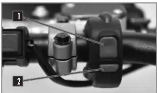
natural_image
Close-up of a mechanical component with labeled parts (1 and 2), no visible text or symbols beyond labelstext_image
Close-up mechanical component with numbered labels pointing to specific partsVelocímetro
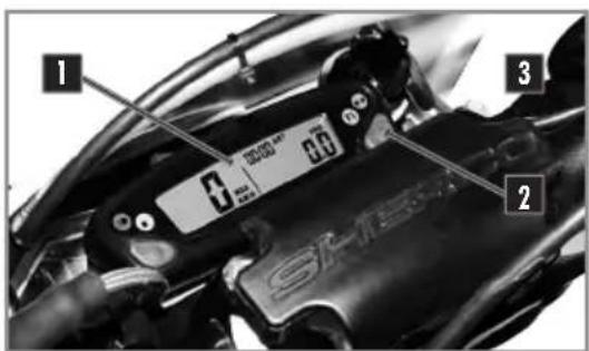
text_image
1 2 3 0 100000 MP 80 SCH-156Contacto de llave
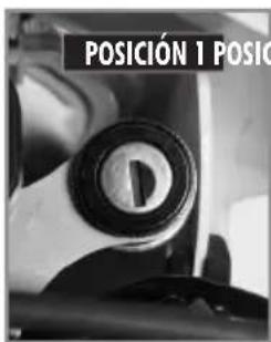
natural_image
Close-up of a mechanical component with a circular lens and metallic end (no visible text or symbols)natural_image
Close-up of a smartwatch with a labeled sensor screen and mechanical components (no readable text or symbols)natural_image
Close-up of a mechanical assembly with visible components and a numbered label (1), no readable text or symbols present.natural_image
Close-up of a vehicle's lower body and wheel assembly, showing mechanical components and no visible text or symbols.text_image
56 MAX KM/W 2019 ART 00:00 34800.6Fig 2 Función MAX
text_image
56 MAX KWH 20-29 ART 34800.6Fig 7 Función ODO
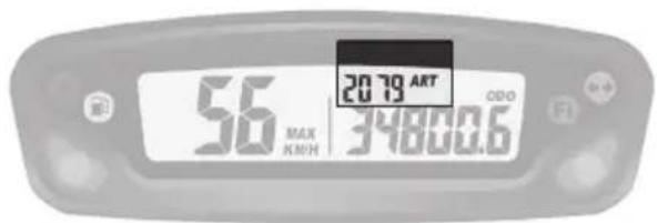
text_image
56 MAX KWH 20:19 ART 34800.6 ODOFig 8 Función ART
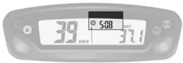
text_image
39 X/MON 5:08 DST 37.1Fig 9 Función Hora
natural_image
Close-up of a white electric scooter's side panel with black seat and cable, no visible text or symbolsnatural_image
Close-up of a gloved hand adjusting a mechanical component with a tool, no visible text or symbolsnatural_image
Close-up of a person adjusting a mechanical component with a tool, no visible text or symbols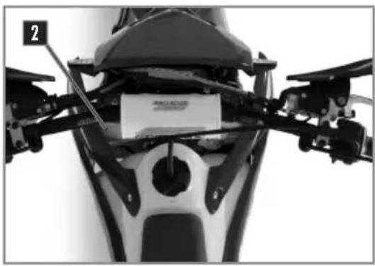
natural_image
Close-up of a motorcycle's head and front view showing mechanical components and a small paper label (no readable text or symbols)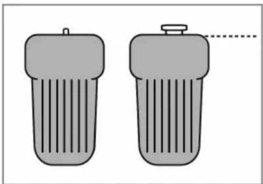
natural_image
Two identical gray cylindrical objects with ribbed surfaces, one with a small protrusion and the other with a dashed line (no text or symbols)Moto horizontal
! ATENCIÓN
natural_image
Close-up of a mechanical component with a white plastic bag attached, no visible text or symbolsnatural_image
Close-up of a car's front wheel and side panel, showing mechanical components and a numbered marker (1) in the corner.! ATENCIÓN
natural_image
Close-up mechanical assembly showing gears and springs (no visible text or symbols)natural_image
Close-up mechanical assembly showing internal components and wiring (no visible text or symbols)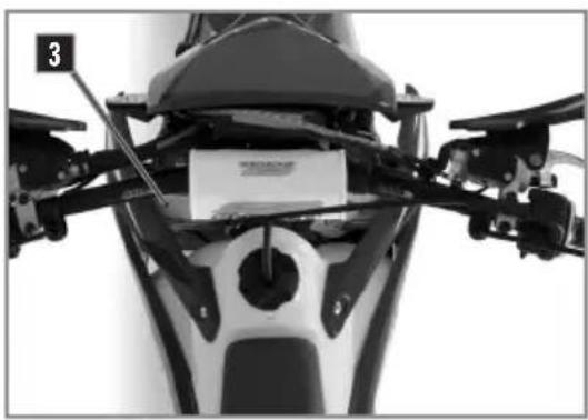
natural_image
Close-up of a motorcycle's front bumper and side-mounted sensors (no visible text or symbols)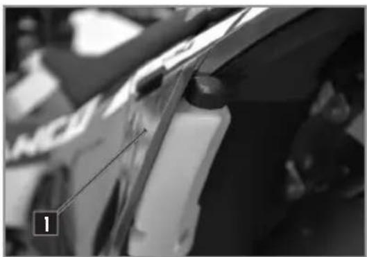
natural_image
Close-up of a car's side panel with a numbered marker (1) pointing to the front wheel, no visible text or symbols on the main subject.natural_image
Close-up of a bicycle brake lever handle and grip mechanism (no text or symbols visible)natural_image
Close-up of a mechanical assembly with a circular component and a metallic housing (no visible text or symbols)natural_image
Close-up of a hand adjusting a mechanical component with a numbered label (2), no visible text or symbols beyond the number.natural_image
Close-up of mechanical components with no visible text or symbolsnatural_image
Close-up of mechanical components with no visible text or symbols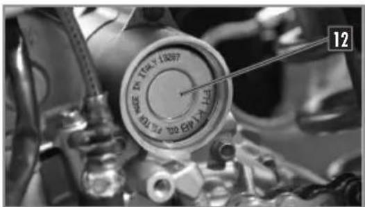
text_image
12natural_image
Close-up of mechanical components with no visible text or symbols
text_image
1 2 3text_image
Technical diagram showing mechanical components with labeled parts and a schematic of piston assembly with arrows indicating motion or force.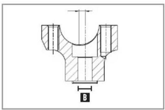
text_image
B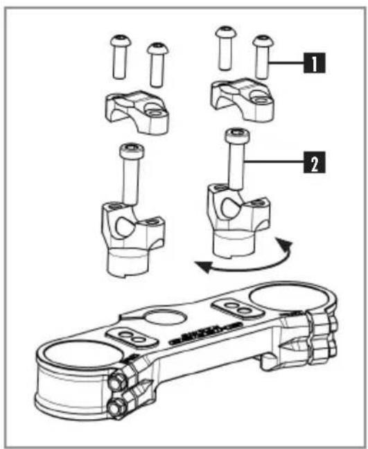
text_image
Technical diagram showing mechanical assembly steps with numbered components and a component photo labeled '发动机'| Handlebar clamps fixing screws | M8x25 | 25Nm |
natural_image
Close-up of mechanical components with numbered annotations (1 and 2) showing no readable text or symbols.natural_image
Close-up of a mechanical assembly with visible gears and springs (no text or symbols)KAYABA RACING
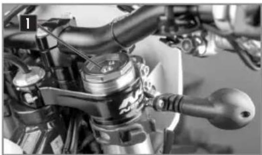
natural_image
Close-up of a motorcycle's internal components and brake lever (no visible text or symbols)KAYABA FACTORY
natural_image
Close-up of a motorcycle's front wheel and drivetrain components (no visible text or symbols)KAYABA RACING
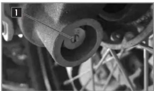
natural_image
Close-up of mechanical components with no visible text or symbolsKAYABA FACTORY
natural_image
Close-up of a vehicle's interior airway with visible engine components and no readable text or symbolsKAYABA
natural_image
Close-up of a black vehicle's side panel with 'SHE' branding visible on the front (no additional text or symbols)KAYABA
natural_image
Close-up of mechanical components with no visible text or symbolsnatural_image
Silhouette of a person riding a dirt bike with visible tire tracks and a labeled radius R3 (no text or symbols beyond the label)text_image
Technical diagram of a mechanical spring assembly with labeled parts 1 and 2natural_image
Mechanical assembly of a coiled spring and cylindrical housing (no text or symbols visible)text_image
COTIE DIANA VILLI ITALYnatural_image
Close-up of a white motorcycle's front view with black and white buttons, showing mechanical components and a numbered label (2) pointing to the side (no text or symbols on the main body)natural_image
Close-up of a gloved hand adjusting a mechanical component with visible wiring and components (no text or symbols)natural_image
Close-up of gloved hands using a tool to adjust or install a mechanical component (no visible text or symbols)natural_image
Close-up of hands adjusting a black helmet component with a numbered label (1) pointing to the part, against a white background.natural_image
Close-up of a mechanical component with a labeled part (2) and a tool inserted, showing no visible text or symbols.text_image
Close-up mechanical component with numbered parts labeled 3 and 4, showing a screwdriver inserted into a housing.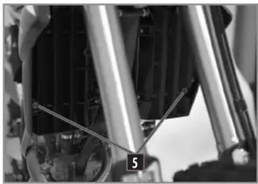
natural_image
Close-up of mechanical components with visible springs and a numbered label '5' (no readable text or symbols beyond the number)natural_image
Close-up of a car's front wheel and radiator assembly (no visible text or symbols)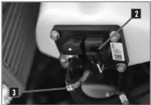
text_image
Close-up mechanical component with numbered parts labeled 1, 2, and 3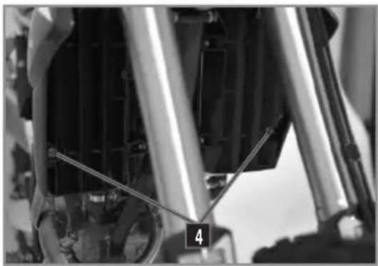
natural_image
Close-up of mechanical components with visible springs and connectors (no text or symbols)natural_image
Close-up of metallic mechanical components with black caps and a coiled shaft (no visible text or symbols)Moto sobre trípode.
natural_image
Close-up of a motor with visible tire, duff, and wheel components (no text or symbols)Moto sobre trípode.
natural_image
Close-up of a mechanical device with wires and connectors, no visible text or symbols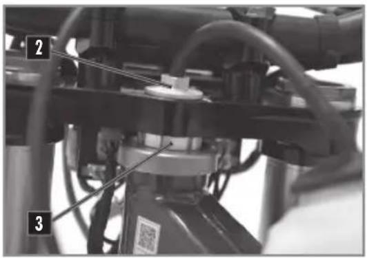
text_image
Technical diagram of a mechanical assembly with numbered components and labeled partsLIMPIEZA DE LA CADENA
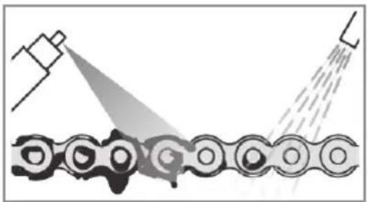
natural_image
Diagram of a mechanical assembly with spray gun spraying through a chain (no text or symbols)natural_image
Close-up mechanical assembly showing a gear and housing component (no visible text or symbols)AJUSTE DEL EMBRAGUE
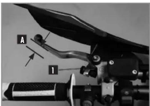
text_image
A 1! ATENCIÓN
natural_image
Close-up of a mechanical lever handle with circular arrow indicating cycle (no text or symbols)CONTROL NIVEL DE LÍQUIDO EMBRAGUE
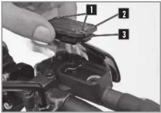
text_image
1 2 3natural_image
Mechanical assembly diagram showing a vehicle's suspension system with labeled components (no readable text or symbols)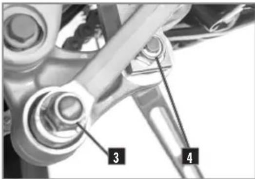
text_image
3 4MONTAJE DEL AMORTIGUADOR
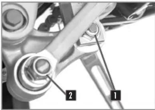
natural_image
Close-up of mechanical components with numbered annotations (1 and 2), no readable text or symbols beyond labels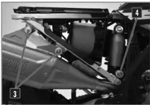
text_image
Technical diagram of a vehicle's suspension system with numbered components labeled 3 and 4Moto sobre trípode.
Desmontar la placa lateral derecha.
text_image
Close-up mechanical component with numbered labels pointing to features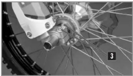
natural_image
Close-up of a bicycle wheel with visible spokes and hub, no text or symbols presentMONTAJE DE LA RUEDA DELANTERA
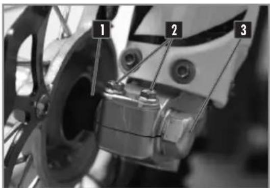
text_image
1 2 3Moto sobre trípode.
natural_image
Close-up of hands installing a mechanical component with labeled parts (1 and 2), no visible text or symbols beyond labels.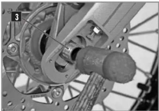
natural_image
Close-up mechanical assembly of a bicycle wheel and gear assembly (no visible text or symbols)Instalar la moto sobre un trípode.
natural_image
Close-up of a bicycle wheel with visible gear and hub, no text or symbols present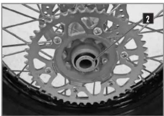
natural_image
Close-up of a bicycle wheel with visible teeth and gear mechanism (no text or symbols)natural_image
Close-up of a bicycle's wheel and gear assembly, showing tread pattern and chain (no text or symbols visible)natural_image
Close-up of a bicycle wheel assembly with visible components and structural details (no text or symbols)natural_image
Close-up of a bicycle tire with a pressure gauge and cable, no visible text or symbolsnatural_image
Close-up of hands using a screwdriver to adjust the wheel rim of a bicycle tire (no text or symbols visible)natural_image
Close-up of a bicycle brake lever with labeled component A (no text or symbols beyond label)natural_image
Close-up of a bicycle brake lever mechanism with handle and grip (no visible text or symbols)natural_image
Close-up of a small electronic camera with black frame and lens, partially covered by mechanical components (no visible text or symbols)natural_image
Close-up mechanical assembly showing two labeled parts (1 and 2) with no visible text or symbolsnatural_image
Close-up of a mechanical component with no visible text or symbolstext_image
Close-up of a mechanical component with numbered parts labeled 1 and 2, showing hand positioning and assembly details.natural_image
Close-up of a mechanical component with labeled part 'A' (no readable text or symbols beyond label)FRENOS
DESMONTAJE DE LAS PASTILLAS DE FRENO DELANTERO Y TRASERO
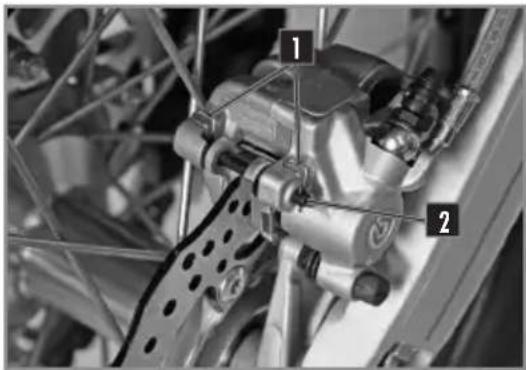
text_image
Technical diagram of a mechanical assembly with numbered components labeled 1 and 2text_image
Close-up mechanical diagram showing two labeled components (1 and 2) on a bicycle frame structurenatural_image
Simple line diagram of a rectangular object with an arrow labeled 'A' and a horizontal line, no text or symbols present.text_image
Technical diagram of a mechanical assembly with numbered components labeled 1 and 2text_image
Labeled mechanical component diagram showing two numbered parts with annotationstext_image
Close-up of a mechanical component with numbered annotations pointing to parts 2 and 3.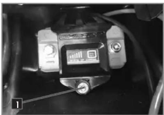
natural_image
Close-up of a mechanical component with wires and a small labeled component (no readable text or symbols)natural_image
Close-up of a car engine bay with visible wiring and components (no text or symbols)natural_image
Close-up of a hand installing or adjusting electronic components in a mechanical assembly (no visible text or symbols)natural_image
Close-up of a motorcycle's front wheel and drivetrain components (no visible text or symbols)natural_image
Close-up of a mechanical assembly with visible gears, springs, and components (no text or symbols)MANTENIMIENTO CIRCUITO ELÉCTRICO
MONTAJE DE LA PLACA DEL FARO
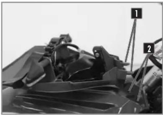
natural_image
Close-up of a mechanical component with numbered parts (1 and 2) and no visible text or symbolsnatural_image
Close-up of a black motorcycle body with visible seatbelt and front wheel (no text or symbols)natural_image
Close-up of a mechanical component with labeled part '2' (no readable text or symbols)MANTENIMIENTO CIRCUITO ELÉCTRICO
AJUSTAR EL ALCANCE DEL FARO
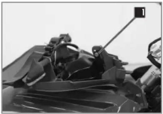
natural_image
Close-up of a motorcycle's front wheel and side seat, showing mechanical components and a numbered component (no text or symbols visible)natural_image
Close-up of a mechanical assembly with visible wiring and components (no readable text or symbols)natural_image
Close-up of a hand holding a handheld electronic device with wires and a coin, no visible text or symbols.text_image
Close-up of a mechanical device with visible label and numbered annotation '1'natural_image
Close-up of a mechanical assembly with visible gears and chains (no text or symbols)text_image
Labeled mechanical component diagram showing numbered parts from 1 to 5text_image
Close-up mechanical component with numbered labels pointing to specific partsInstrumentenanzeige
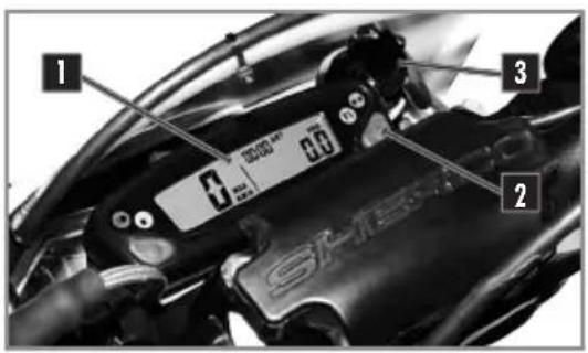
text_image
1 3 2 SAMSSchlüsselschalter
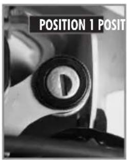
text_image
POSITION 1 POSIT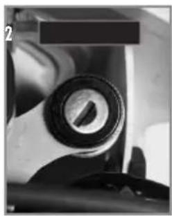
natural_image
Close-up of a mechanical component with a cylindrical lens and metallic end (no visible text or symbols)Blinkerschalter
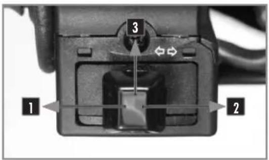
text_image
1 2 3natural_image
Close-up of a smartwatch with a labeled sensor (number 1) on its screen, mounted on a mechanical device (no visible text or symbols)natural_image
Close-up of a mechanical component with a labeled section (no readable text or symbols)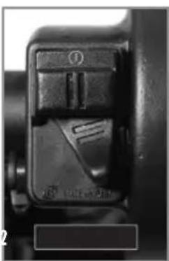
natural_image
Close-up of a mechanical component with a handle and internal structure (no visible text or symbols)natural_image
Close-up of a mechanical assembly with visible components and a numbered label (1), no readable text or symbols present.natural_image
Close-up of a mechanical assembly with visible gears and a tool (no text or symbols)text_image
39 KM/W SNO SUB DST 37.1Abb. 1 Funktion SPD
text_image
56 MAX KWH 34800.6 20:10 ART 000 E1Abb. 7 Funktion ODO
text_image
56 MAX MINH 2019 ART 34800.6 ODOAbb. 8 Funktion ART
text_image
5:08 39 KM/H 37.1natural_image
Close-up of a white electric scooter's side panel with black seat and cable (no visible text or symbols)natural_image
Close-up of a gloved hand adjusting a mechanical component with a tool, no visible text or symbolsnatural_image
Close-up of a person's hands holding a small mechanical component, possibly a tool or device, in a workshop setting (no visible text or symbols)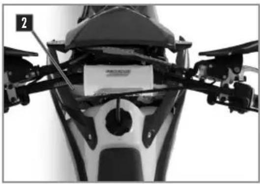
natural_image
Close-up of a motorcycle's head and neck assembly with visible mechanical components (no text or symbols)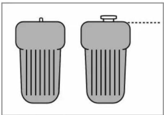
natural_image
Two gray cylindrical objects with ribbed surfaces, one with a small protrusion and the other with a dashed line (no text or symbols)Motorrad horizontal
! ACHTUNG
natural_image
Close-up of a car interior showing a white plastic bottle and attached cable, with no visible text or symbols.natural_image
Close-up of a car's front wheel and side brackets, no visible text or symbols! ACHTUNG
natural_image
Close-up mechanical assembly showing gears and hoses (no visible text or symbols)HINWEIS
natural_image
Close-up mechanical assembly showing internal components and a numbered label (2), no readable text or symbols present.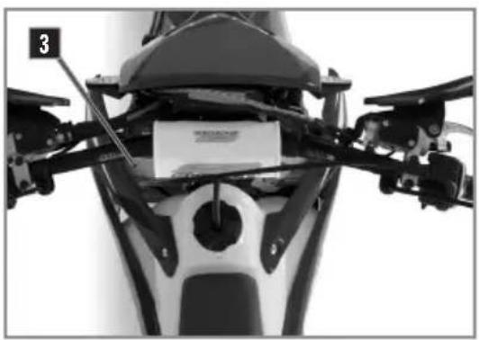
natural_image
Close-up of a motorcycle's front view showing engine, drivetrain, and gear assembly (no visible text or symbols)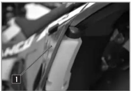
natural_image
Close-up of a car's front wheel and side panel, showing no visible text or symbolsnatural_image
Close-up of a bicycle brake lever handle and grip mechanism (no text or symbols visible)natural_image
Close-up of a mechanical assembly with a circular component and metallic parts (no visible text or symbols)natural_image
Close-up of a hand adjusting a mechanical component with a numbered label (2) and wiring, no readable text or symbols present.natural_image
Close-up of mechanical components with no visible text or symbolsnatural_image
Close-up of mechanical components with no visible text or symbols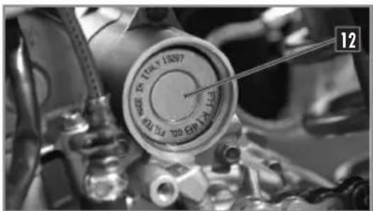
text_image
12 13007 13007 13007 13007 13007text_image
12 TIRLY LEEP PILK TIN KON 5.0 TO MENI 30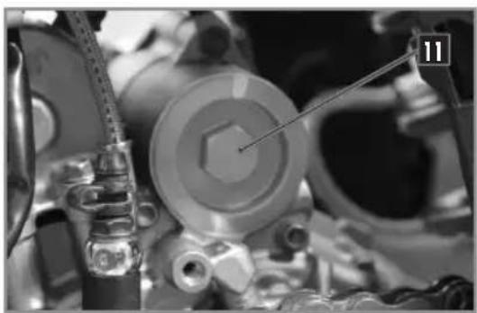
natural_image
Close-up of mechanical components with no visible text or symbols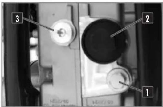
text_image
1 2 3text_image
Technical diagram showing mechanical components with labeled parts and a schematic of a piston assembly with arrows indicating motion or force.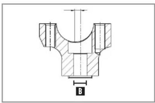
text_image
B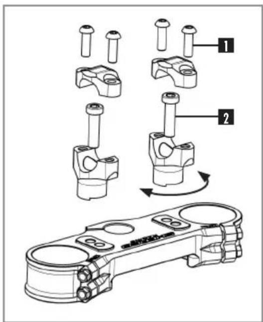
text_image
Technical diagram showing mechanical assembly steps with numbered components and a 3D model of a piston-cylinder assembly.natural_image
Close-up of mechanical components with numbered annotations (1 and 2) pointing to specific parts, no readable text or symbols present.natural_image
Close-up of a mechanical assembly with visible gears and springs (no text or symbols)KAYABA RACING
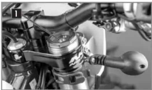
natural_image
Close-up of a motorcycle's internal engine compartment showing valve and shaft (no visible text or symbols)KAYABA FACTORY
natural_image
Close-up of a motorcycle's front wheel and drivetrain components (no visible text or symbols)KAYABA RACING
natural_image
Close-up of mechanical components with no visible text or symbolsKAYABA FACTORY
natural_image
Close-up of a vehicle's air lift and wheel assembly (no visible text or symbols)KAYABA
natural_image
Close-up of a black vehicle's side panel with 'SHE' branding visible on the hood (no additional text or symbols)KAYABA
natural_image
Close-up of mechanical components with no visible text or symbolsnatural_image
Silhouette of a person riding a dirt bike with visible tire tracks and a labeled radius R3 (no text or symbols beyond the label)text_image
Technical diagram of a mechanical spring assembly with labeled parts 1 and 2natural_image
Mechanical component with coiled spring and cylindrical housing (no visible text or symbols)text_image
COTIE DIANA VILLI ITALYnatural_image
Front view of a motorcycle's head and torso with labeled component '2' (no text or symbols beyond label)natural_image
Close-up of a person adjusting a vehicle wheel assembly (no visible text or symbols)natural_image
Close-up of hands using a tool to adjust or install a mechanical component, no visible text or symbolsnatural_image
Close-up of hands adjusting a black helmet component with a small square tag (no visible text or symbols)natural_image
Close-up of a car seatbelt buckle and jaw (no text or symbols visible)text_image
Close-up mechanical component with numbered parts labeled 3 and 4, showing a tool inserted into a housing.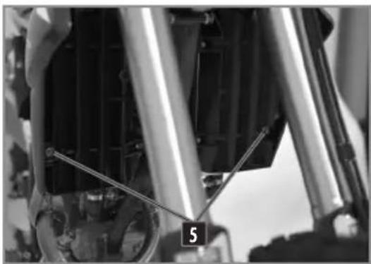
natural_image
Close-up of mechanical components with visible springs and a numbered label '5' (no readable text or symbols beyond the number)natural_image
Close-up of a car's front wheel and radiator assembly (no visible text or symbols)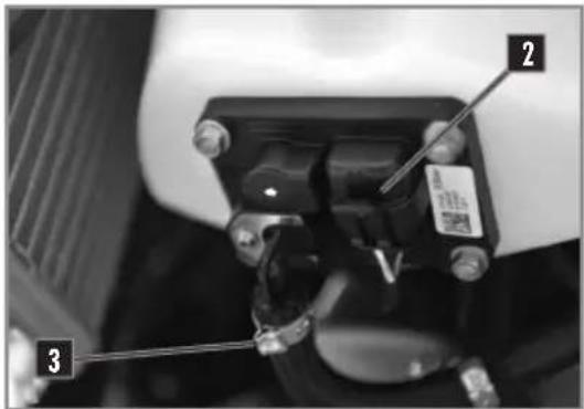
text_image
Close-up mechanical component with numbered parts labeled 1, 2, and 3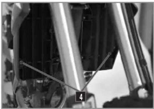
natural_image
Close-up of mechanical components with visible springs and tubing (no text or symbols)natural_image
Close-up of metallic mechanical components with black caps and rings (no visible text or symbols)natural_image
Close-up of a motor dork wheel and tire assembly with motion arrows indicating rotational direction (no text or symbols)natural_image
Close-up of a mechanical device with wires and connectors, no visible text or symbols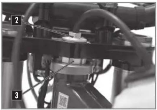
text_image
Technical diagram of a mechanical assembly with numbered components and labeled partsREINIGUNG DER KETTE
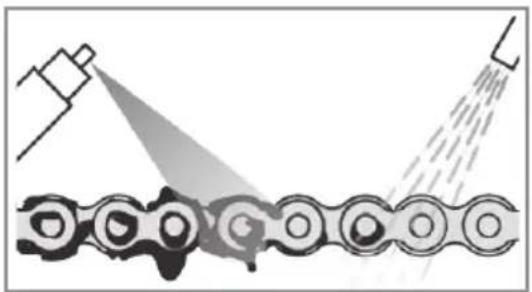
natural_image
Diagram showing a mechanical assembly with spray gun spraying through a chain (no text or symbols)natural_image
Close-up mechanical assembly showing a clamping mechanism with no visible text or symbolsnatural_image
Close-up of a mechanical lever handle with a circular arrow indicating cycle (no text or symbols)text_image
Technical diagram of a vehicle suspension system with labeled components and numbered parts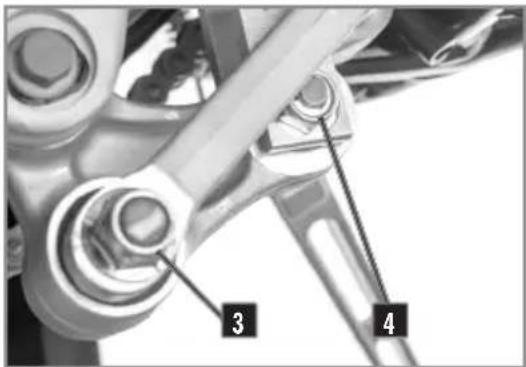
text_image
3 4WIEDEREINBAU DES STOSSDÄMPFERS
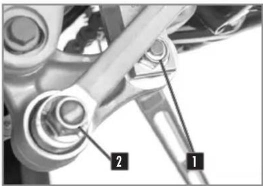
text_image
Technical diagram of a mechanical assembly with labeled parts 1 and 2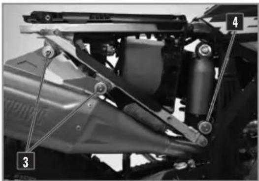
natural_image
Mechanical assembly diagram showing a vehicle's suspension system with labeled components (no text or symbols present)text_image
Close-up mechanical component with numbered labels pointing to features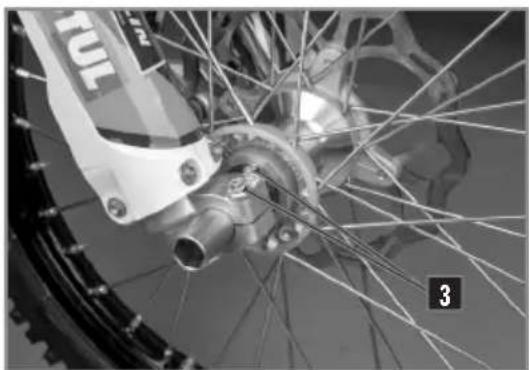
natural_image
Close-up of a bicycle wheel with visible spokes and hub, no text or symbols presentIEDEREINBAU DES VORDERRADS
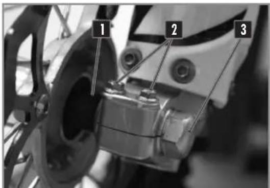
text_image
1 2 3natural_image
Close-up of hands installing a mechanical component with labeled parts (1 and 2), no visible text or symbols beyond labels.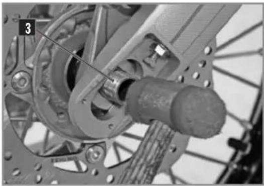
natural_image
Mechanical assembly diagram showing a motor and wheel components (no text or symbols visible)natural_image
Close-up of a bicycle wheel with visible gear and hub, no text or symbols present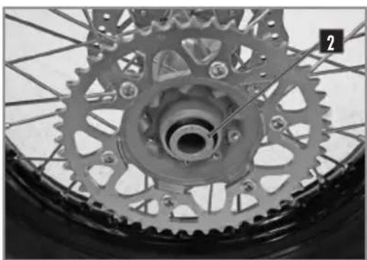
natural_image
Close-up of a bicycle wheel with visible teeth and gear mechanism (no text or symbols)natural_image
Close-up of a bicycle wheel with visible track and gear teeth (no text or symbols)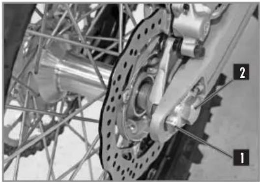
natural_image
Close-up of bicycle wheel assembly with visible components and no text or symbolsKONTROLLE DES REIFENDRUCKS
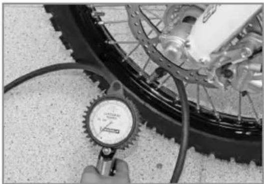
natural_image
Close-up of a bicycle tire with a pressure gauge and cable, no visible text or symbolsnatural_image
Close-up of hands using a screwdriver to adjust the wheel rim and disc brake system (no text or symbols visible)natural_image
Close-up of a bicycle brake lever with labeled component A (no text or symbols beyond label)natural_image
Close-up of a bicycle brake lever mechanism with handle and grip (no visible text or symbols)natural_image
Close-up of a small electronic device with a black lid and lens, partially covered by mechanical components (no visible text or symbols)natural_image
Close-up mechanical assembly showing a lever and component with numbered labels (1 and 2), no readable text or symbols beyond labels.natural_image
Close-up of a mechanical component with no visible text or symbolstext_image
Close-up of a mechanical component with numbered parts labeled 1 and 2, showing hand positioning and assembly details.natural_image
Close-up of a mechanical component with labeled part 'A' (no other text or symbols visible)BREMSEN
text_image
Technical diagram of a mechanical assembly with numbered components labeled 1 and 2text_image
Technical diagram of a bicycle suspension system with labeled components 1 and 2KONTROLLE DER BREMSBELÄGE VORN UND HINTEN
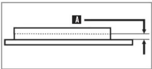
natural_image
Pure schematic diagram of a mechanical or electrical component with no text, numbers, or symbolstext_image
Technical diagram of a mechanical assembly with numbered components labeled 1 and 2text_image
Labeled mechanical component diagram showing parts numbered 1 and 2, likely for assembly or maintenance instructions.text_image
Close-up of mechanical components with numbered annotations pointing to parts 2 and 3natural_image
Close-up of a mechanical component with wires and a labeled sensor (no readable text or symbols)natural_image
Close-up of a car's engine compartment showing a component being inserted, with no visible text or symbols.natural_image
Close-up of a hand installing or adjusting electronic components in a mechanical assembly (no visible text or symbols)natural_image
Close-up of a motorcycle's front wheel and drivetrain components (no visible text or symbols)natural_image
Close-up of a motorcycle's front wheel assembly with visible hoses and levers (no text or symbols)natural_image
Close-up of a mechanical component with numbered parts (1 and 2) and no visible text or symbolsnatural_image
Close-up of a black motorcycle body with visible frame and seat, no text or symbols presentnatural_image
Close-up of a mechanical assembly with labeled component '2' (no readable text or symbols)natural_image
Close-up of a motorcycle's seatbelt with a visible weight labeled '1' (no text or symbols on the main subject)natural_image
Close-up of a mechanical component with visible wiring and a labeled tag (no readable text or symbols)natural_image
Close-up of a hand holding a handheld electronic device with wires and a coin, no visible text or symbols.CLEANING PRODUCTS AND CONSUMABLES
natural_image
Side profile of a black and white DHTR 6500 motorcycle with visible tracks, tires, and gear (no text or symbols on the body)SHERCO recommends


KENNY




GALFER






SCOTT


OXFLIGHT