— Motorcycle — Mode d'emploi PDF")
CityCorp (2003) - Motorcycle Sherco - Free user manual and instructions
Find the device manual for free CityCorp (2003) Sherco in PDF.

| Product type | Motorcycle 125 4T |
| Maximum power | 8.0 kW at 8000 rpm |
| Maximum torque | 10.41 Nm at 6500 rpm |
| Displacement | 123.7 cm³ |
| Engine type | 4-stroke, single cylinder, air-cooled |
| Bore x stroke | 54 x 54 mm |
| Compression ratio | 10:1 |
| Starting | Kick + electric starter |
| Fuel | Unleaded 95/98, tank 7.5 L |
| Transmission | 5-speed, chain |
| Clutch | Multi-disc oil bath |
| Dimensions (L x W x H) | TT: 2110 x 830 x 1220 mm; SM: 2060 x 830 x 1190 mm |
| Wheelbase | 1450 mm |
| Dry weight | 111 kg |
| Front tires | TT: 3.00-21; SM: 100/80-17 |
| Rear tires | TT: 4.10-18; SM: 130/70-17 |
| Brakes | Hydraulic disc front and rear |
| Lighting | Headlight 12V 35/35W, tail light 12V 21/5W, turn signals 12V 10W |
| Engine oil | SAE 10W50, 1 L |
| Running-in | 500 km, mandatory inspection at dealership |
| Warranty | 1 year parts, unlimited mileage |
| Periodic maintenance | Every 1000 km then 6000, 12000, etc. (see manual) |
| Safety | Side stand with switch, kill switch |
Frequently Asked Questions - CityCorp (2003) Sherco
User questions about CityCorp (2003) Sherco
0 question about this device. Answer the ones you know or ask your own.
Ask a new question about this device
Download the instructions for your Motorcycle in PDF format for free! Find your manual CityCorp (2003) - Sherco and take your electronic device back in hand. On this page are published all the documents necessary for the use of your device. CityCorp (2003) by Sherco.
USER MANUAL CityCorp (2003) Sherco
INDEX
ENGLISH
P.3

P.19
SPANISH
P.20

P.37
FRANÇAIS
P.38

P.55
Warranty manuel - Manual de Garantia - Carnet de garantie
P.56

P.79
INTRODUCTION
Congratulations! You are now the owner of a Sherco 125 CityCorp 4 Stroke Motorcycle. You will enjoy many miles of riding pleasure if you follow the instructions in this manual.
This manual explains the function, inspection, basic maintenance and tuning of your new Sherco Motorcycle. Do not hesitate to contact your local Sherco Dealer if you have any questions about these procedures.
We recommend that you read and understand everything in this manual before you ride your motorcycle.
In order to keep your new Sherco Motorcycle operating properly it is necessary that you follow the maintenance procedures outlined in this manual.
The motorcycle shown in the pictures might be slightly different from the one that you have purchased, however the procedures described are accurate.
SUMMARY
Technical data P.5
Identification numbers .....P6
Vehicle description P7
Vehicle identification .....P7
Controls .....P8
First runs .....P9
Driving P10
Security rules .....P11
Overhaul and setting....P12
Washing and Parking P20
TECHNICAL DATA
PERFORMANCE
Maximum power : 8.0 kW a 8000 rpm
Maximum torque : 10.41 Nm a 6500 rpm
DIMENSION
Overall length : TT : 2110 mm SM : 2060 mm
Overall width : 820 mm
Type : 4 stroke, single cylinder, liquid cooled
Starting system : Kick and electric starter
Carburator : Mikuni VM20
Ignition system : Electronic CDI
Spark plug : NGK CR7HSA / U22 FSR-U/N-Denso
Gear box oil : 1 Liter, SAE 10W50 IPONE
TRANSMISSION
Type : 5 speed
Clutch : Wet, multi-disc
Transmission system : Chain drive
Primary reduction ratio : 3,58 (68/19)
Secondary reduction ratio : 3,14 (44/24)
Gear ratio : 1st 2.64 (37/14) 4th 1.05 (23/22)
2nd 1.78 (32/18) 5th 0.88 (21/24)
3rd 1.32 (25/19)
FRAME
Tire mark : Michelin
Size
Front : TT: 3.00 - 21
SM: 100/80 - 17
Rear : TT: 4.10 - 18
SM: 130/70 - 17
Fuel tank capacity : 7.5 L, 87/93 octane unleaded gasoline
ELECTRICAL EQUIPEMENT
Headlight : 12 V 35/35 W
Tail/brake light : 12 V 21/5 W
Flasher light : 12 V 10 W
TT : Enduro model
SM : Supermotard model
Technical data is subject to change without prior notice.
IDENTIFICATION NUMBERS
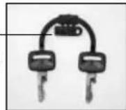
Record in the spaces below, the ignition key number, the steering lock number and the vehicle serial number of your motorcycle.
Ignition key number (see the picture)

Steering lock key number (see the picture)
Engine serial number (see the picture)
key number
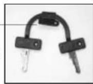
key number
VEHICLE DESCRIPTION
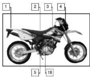
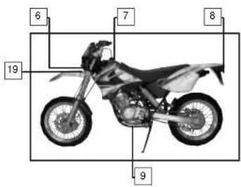
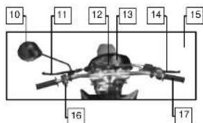
- Rear turn signal lights 11. Clutch lever
- Seat 12. Main electrical switch
- Fuel tan 13. Speedometer
- Front turn signal lights 14. Front brake lever
- Rear brake pedal 15. Right hand rear-view mirror (optional)
- Headlight 16. Handlebar control switch
- Fuel tank cap 17. Throttle
- Tail light / Brake light / License plate light 18. Kick starter lever
- Gearshift lever 19. Steering lock
- Left hand rear-view mirror 20. Steering blocking device
VEHICLE IDENTIFICATION
Vehicle serial number
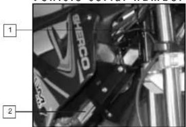
- The serial number of the vehicle is recorded on the right side of the steering tube.
- The identification plate is attached to the right side of the frame. This plate indicates the emissions control number of the vehicle and the noise level in dba at a given RPM.
The identification plate also includes the machine serial number.
CONTROLS
Main switcher Dashboard
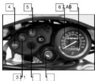
- Main electrical switch (two active positions)
a. Engine can be started
b. Engine is off and cannot be started - High beam indicator light.
- Neutral warning light: illuminated (engine must be running) when the gearbox is in the neutral position.
- Turn signal indicator light: flashes when the turn signals flash.
- Headlight indicator light: illuminated when the headlight is in the low beam position.
- Speedometer.
- Odometer in kilometers.
Left Handlebar Control Switch
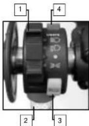
- Lights switcher
- Turn signal switch.
- Horn button.
- Electric start button.
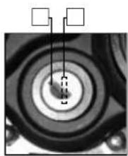
natural_image
Close-up of a mechanical component with concentric rings and mounting holes (no visible text or symbols)Gearshift lever
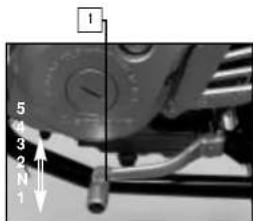
- The gear shift lever which is located on the left side of the engine is used to select the 5 gears in the transmission.
Fuel petcock

natural_image
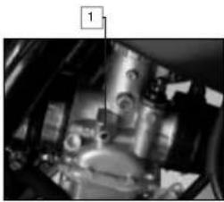
Close-up of a mechanical joint or connector with a metallic rod inserted (no visible text or symbols)- The fuel petcock has three positions:
OFF: When the lever is in this position, fuel will not flow. Always return the lever to this position when the engine is not running.
ON: With the lever in this position, fuel flows to the carburetor. Normal riding is done with the lever in this position.
RES: This is the reserve position. If you run out of fuel while riding, move the lever to this position.
INITIAL OPERATION
The break in period if 500 km. During this period it is mandatory that you follow the procedures described below.
If these procedures are not followed the life of your motorcycle may be drastically reduced.
■ Do not accelerate or race the engine immediately after starting. Let the engine idle for a few minutes in order for it to warm up.
■ Do not run at full load during the break in period.
In order to validate the manufacturers warranty, you must return your Sherco motorcycle to your authorized Sherco dealer at the end of the 500 km break in period.
Riding your Motorcycle
Starting a cold engine :
- Turn the fuel petcock to the ON position.
- Set the sidestand up (the sidestand is equipped with a switch which prevents the engine from starting when it is down)
- Turn the ignition key to the on position, first position to the right. (clockwise)
- Using the gearshift lever, place the transmission in neutral.
- Engage the choke and slightly open the throttle.
- To start the motor push the engine start button, once the engine is started remove your finger from the button.
The engine may also be started by using the kick starter lever. Follow the same process as above but instead of pushing the engine start button, unfold the kick starter lever and push down on it with your foot. Once the engine starts return the kickstarter lever to its original position.
- Allow the engine to warm up for several minutes in neutral before shifting into 1st gear and riding off.
Shifting gears
The gear shift lever positions are shown on page 8. To find neutral, push down on the pedal until it is in first gear (you will feel a resistance to further movement). Lift up slightly on the pedal.
- Close the throttle and pull in the clutch lever.
- Step on the gear shift lever and place the transmission into first gear.
- Smoothly open the throttle and slowly release the clutch lever. Once you have reached the proper speed, shift into the next higher gear.
Starting warm engine :
Follow the above instructions but omit steps 5 and 7. Accelerate the engine slightly after it starts.
Stopping:
Using the ignition key stop the engine, remove the key from the main switch and place the petcock in the off position.
You must know these functions completely prior to operating your motorcycle for the first time.
SAFTEY
■ We recommend that you always wear an approved helmet when you ride your motorcycle.
■ For optimum safety and reliability you have to keep your motorcycle in good repair with a rigorous maintenance schedule.
■ Gasoline is inflammable, fill the fuel tank when the engine is not running.
■ Exhaust gases are toxic, do not run the engine in a closed space.
■ Always park the motorcycle on a flat hard surface. Do not park the motorcycle on a soft surface or on a slope. Check the stability before leaving your motor cycle.
■ You should inspect the following items daily, before you ride your motorcycle:
- Tires: :Check for wear and pressure.
- Engine oil: : Level. (see the maintenance and adjustment chapter)
- Fuel: : Make sure there are no leaks.
- Primary drive chain: : Tightness. (see the maintenance and adjustment chapter)
- Steering: : Make sure that it turns freely.
- Brakes: : Check for proper operation, make sure that there is plenty of brake fluid and that the pads are serviceable. (see the maintenance and adjustment chapter)
- Throttle control: : Check for proper operation, the throttle should turn freely and not stick. (see the maintenance and adjustment chapter)
- Clutch: : Check for proper operation. (see the maintenance and adjustment chapter)
- Sidestand: : Check the operation of the safety switch, the engine should not start when the sidestand is down and should run when it is up.
- Electrical System: : Check the operation of the horn, the lights and the starting system. Fasteners (bolts, nuts, screws): Inspect all bolts, nuts and screws, make sure they are properly tightened.
If during this inspection you find a defect, refer to the Maintenance and Adjustment chapter which follows, or contact your authorized Sherco dealer.
| MAINTENANCE AND SETTINGS | |||||||||
| OPERATION | FREQUENCY (the first of either) | See Page | |||||||
| EVERY | DISTANCE (in KM) | ||||||||
| 1000 | 6000 | 12000 | 18000 | 24000 | 30000 36000 | ||||
| Idle speed | C | . | . | . | 15 | ||||
| Throttle handle play | S - C - 0 - △ | . | . | . | 15 | ||||
| Spark plug gap | N - C - 0 - △ | . | . | . | . | . | . | 16 | |
| Air filter | N - 0 | . | 0 | 0 | 16 | ||||
| Brake pad and disc wear | C | . | . | . | . | . | . | 17 | |
| Brake fluid level | C | . | . | . | . | . | . | 14 | |
| Brake fluid | S - 0 | 2 years | 0 | 17 | |||||
| Front brake, back brake | C | . | . | . | . | . | . | / | |
| Clutch | △ | . | . | . | . | . | . | 18 | |
| Clutch | C ou 0 | 0 | 0 | 19 | |||||
| Engine oil | S - 0 | 0 | 0.0 | 0 | 16 | ||||
| Oil filter | 0 | 0 | 0 | 19 | |||||
| Transmission chain | L - 0 - △ | 1000 kms | 20 | ||||||
| Transmission chain movement | C - 0 - △ | 1000 kms | 22 | ||||||
| Tire wear | C | . | . | . | . | . | . | 23 | |
| Steering | S - O - △ | . | . | . | . | . | . | / | |
| Tightness of wheel spokes and disks | S - 0 - △ | . | . | . | . | . | . | / | |
| Tightness of nuts, bolts, joints | C - 0 - △ | . | . | . | . | . | . | / | |
| General lubrication | . | . | . | . | . | . | / | ||
| Front fork oil | S - 0 | . | . | . | / | ||||
| Swing arm pivot | S - 0 - L - △ | . | . | / | |||||
| Lubricato steering bearings | S - 0 - L - △ | . | . | / | |||||
| Master cylinder | S - 0 | 2 years | . | ||||||
| Calliper | S - 0 | 2 years | . | ||||||
| Brake hose | S - 0 - C | 2 years | . | 0 | |||||
| Fuel inlet tube | S - 0 - C | 2 years | . | 0 | |||||
| Valve clearance | S - △ | 2 years | . | . | . | / | |||
| Oil strainer | N | . | . | . | / | ||||
| KEY: Inspection C - Setting △ - Replace 0 - Obligatory operation . - Contact a SHERCO dealer S - Clean N - Lubricate L | |||||||||
Engine IDLE speed
Oil pump adjustment
natural_image
Close-up of mechanical components with no visible text or symbols- Start the engine and let it warm up for a few minutes.
- Adjust the idle speed by turning the adjustment screw
Spark plugs
| Standard spark plugs | NGK CR7HSAU22 FSR-U/N Denso |
| Torque 20-25 Nm | |
| Electrode gap | |
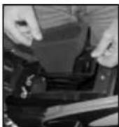
Air filter
1
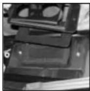
2
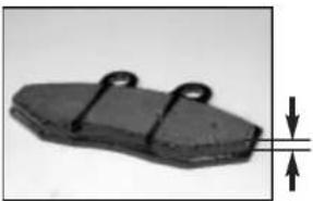
Brake pad wear
natural_image
Close-up of a mechanical component with two metal clips and a dimension arrow (no text or symbols)Remove both pads, if one or both pads measure less than 1mm they should be replaced.
- Remove the seat.
- Remove the air filter cover (1).
- Remove the air filter (2).
- Clean the element with soap and water, squeeze the element to remove any excess water. Allow to dry completely.
- Impregnate the element with specialair filter oil.
IPONE ref. 530
- Reinstall the air filter element.
- Reinstall the cover, making sure that it makes good contact with the airbox.
8 Reinstall the seat.
Brake fluid level
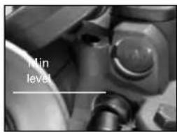
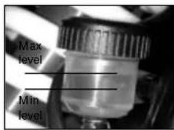
If the brake fluid level is below the minimum level, add EIPONE DOT 4 brake fluid to the maximum mark. Always use the same type of brake fluid.
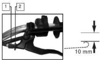
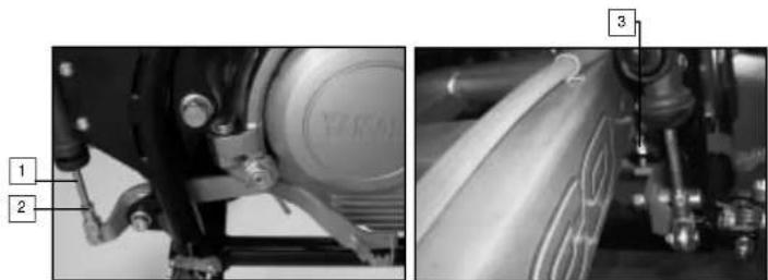
Front brake adjustment
- Loosen the lock nut (1).
- Turn the adjuster (2) until you obtain a 10 mm (approx.) clearan ce between the brake lever and the handlebar grip.
- Tighten the lock nut (1).
Rear brack adjustment
natural_image
Mechanical assembly diagram showing components like a brake caliper and wheel assembly (no text or labels visible)■ The top of the brake pedal should be approx. 15 mm belos the top of the foot peg.
- Loosen the lock nut (2).
- Turn the adjuster (1) until you obtain the 15 mm dimension. Apply pressure to the brake pedal when you have the correct dimension.
- Tighten the lock nut (2).
■ The rear brake pedal should have a clearance of approx. 3 mm with the stop screw.
-
- Loosen the lock nut (3).
- Turn the adjuster until you obtain the 3 mm dimension.
- Tighten the lock nut (3).
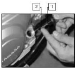
Clutch lever adjustment
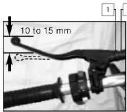
There are two places to adjust the clutch cable: one is on the lever and the other is on the cable near the engine. This illustration shows the clutch lever adjustment.
- Loosen the lock nut (1).
- Adjust the adjuster (2) until you obtain a free play of approx. 10 to 15 mm.
- Tighten the lock nut (1).
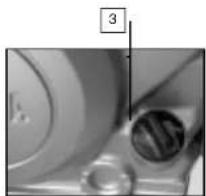
Engine oil
natural_image
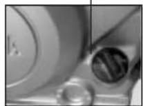
Close-up of a mechanical component with circular features and a numbered label '3' (no readable text or symbols beyond the number)■ Check the oil level (stop the engine and wait a few minutes)
1. Stand the vehicle perpendicular to the ground.
2. Remove the cap (2) and check the oil level.
3. If the level is low add the correct amount of the approved oil to bring it to the correct level.
4. Replace the cap.
■ Oil change :
- Warm up the engine and then shut it off.
- Place the vehicle over an approved receptacle.
- Remove the oil drain plug (3). Note: the picture does not look like the drain plug
- Once the oil has completely drained, replace the drain plug (3) and torque it to 18 Nm.
- Remove the cap (2) and fill the engine with the approved amount
Drive chain adjustment
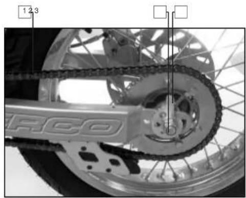
natural_image
Close-up of a motorcycle's front wheel and chain track (no visible text or symbols)■ To check the drive chain for slack:
- The wheels have to be on the ground.
- The motorcycle has to be vertical.
- No one can be on the motorcycle.
■ If the vertical deflection is between 25 and 40 mm the chain must be adjusted.
- Loosen the rear wheel axle nut (2).
- Turn the chain adjusters (3) on both sides of the motorcycle until the chain deflection is between 12 and 24 mm. Make sure that the adjusters are in the same position on both sides.
- Tighten the rear wheel axle nut (2) to 90 Nm.
We recommend that you lubricate the chain with chain lubricant.
SPRAY CHAIN 📄 IPONE REF. 704/702
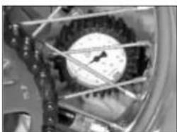
Tires
■ Tire pressure:
- Check the tire pressure on a regular basis with an accurate tire pressure gauge.
- The tire pressure must comply with the chart shown below.
■ Tire wear and damage:
- Check the tread depth on a regular basis with a tread depth gauge.
- If the tread depth is less than 2 mm it is mandatory that the tire be replaced.
- Check the tires to make sure that they do not have any cuts or bulges.
- If there is a lot of damage to the tires it is mandatory that you replace them.
natural_image
Close-up of a mechanical component with a dial indicator and internal structure (no visible text or symbols)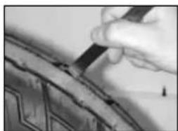
natural_image
Close-up of a hand using a tool to mark a dark object on a curved surface (no visible text or symbols)| Maximum Load | 180 kg | |||
| Max load(Total weight of lugages,passenger and pilot) | 165 kg | |||
| Pressure(cold condition) | ENDURO SUPERMOTARD | |||
| Front | Rear Front | Rear | ||
| Until 90 kg | 130kPa(1.3 kg/cm2) | 150kPa(1.5 kg/cm2) | 180kPa(1.8 kg/cm2) | 200kPa(2 kg/cm2) |
| Between 90 kgand max load | 150kPa(1.5 kg/cm2) | 180kPa(1.8 kg/cm2) | 200kPa(2 kg/cm2) | 220kPa(2.2 kg/cm2) |
CLEARING AND STORAGE
■ SHERCO recommends that you clean your new SHERCO 125 on a regular basis in order to maintain its appearance and prolong its life.
- Cover the exhaust outlet and the air filter intake with an appropriate cover. (a piece of plastic with a rubber band will work)
- To clean the engine, apply a good quality degreaser, scrub with a brush and then rinse the engine with a water hose.
MOTO WASH IPONE ref.768
- Wash the motorcycle first with a garden hose.
- Wash the rest of the vehicle with hot soapy water.
- Rinse with water.
- Dry with a chamois or a clean lint free cloth.
- Dry the chain and lubricate it with chain lubricant. SPRAY CHAIN ☐IPONE ref. 704/702
- Once you are finished cleaning the bike remove the covers from the intake and the exhaust. Start the engine and let it idle a few minutes.
Avoid the use of high pressure washers, the water can enter the bearings, the steering housing, etc. and cause severe damage.
Use a detergent specifically designed to wash automobiles or motorcycles, this will eliminate the possibility of damage to the tires.
■ Before storing the vehicle for a prolonged period (more than two months), it is recommended that you follow these instructions:
- Wash the motorcycle as described above.
- Drain the fuel tank and the carburetor.
- Remove the spark plug and place some drops of engine oil in the cylinder.
Replace the spark plug and turn the engine over several times with the kick star ter with the ignition switch in the off position, this will cover the internal sur faces of the cylinder with oil. SPRAY PROTECTOR3 LIPONE ref. 731
- Lubricate all of the pivot points and cables. SPRAY PROTECTOR3 IPONE ref. 731
- Lift the motorcycle in order that the wheels leave the ground.
- Cover the exhaust exit with a piece of plastic to keep moisture from entering the engine.
- Place a thin coating of engine oil on all non painted metallic surfaces. SPRAY PROTECTOR3 📄 IPONE ref. 731
- Cover the motorcycle with an appropriate cover.
INTRODUCCIÓN

natural_image
Close-up of a mechanical component with concentric rings and mounting holes (no visible text or symbols)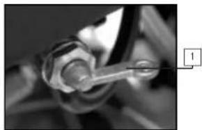
natural_image
Close-up of a mechanical joint or connector with no visible text or symbolsnatural_image
Close-up of a mechanical component with no visible text or symbolsnatural_image
Close-up of a black mechanical component with two side clips and a downward arrow indicating force or measurement (no text or symbols)natural_image
Mechanical assembly diagram showing two views of a vehicle's wheel and suspension components (no text or symbols)natural_image
Close-up of hands adjusting a black object with a circular inset showing a hole (no visible text or symbols)
natural_image
Close-up of a mechanical device with a dial and mesh structure (no visible text or symbols)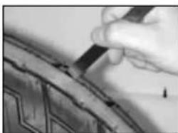
natural_image
Close-up of a hand using a tool to mark a patterned surface (no text or symbols visible)natural_image
Close-up of a mechanical joint or connector with a metallic rod (no visible text or symbols)natural_image
Close-up of a mechanical component with no visible text or symbolsnatural_image
Mechanical assembly diagram showing two views of a vehicle wheel and suspension components (no text or symbols)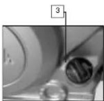
natural_image
Close-up of a mechanical component with circular features and a numbered label '3' pointing to a feature (no readable text or symbols beyond the number)natural_image
Close-up of a mechanical component with internal gears and brackets (no visible text or symbols)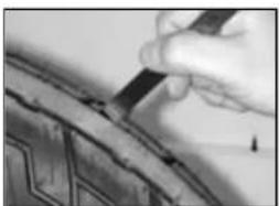
natural_image
Close-up of a hand using a tool to cut or mark a dark, curved object (no visible text or symbols)| Charge maximale(poids total des bagages,du pilote, du passager etdes accessoires) | 180 kg | |||
| Pressionà froid | ENDURO SUPERMÔTARD | |||
| Avant | Arrière Avant | Arrière | ||
| Jusqu'à 90 kg | 130kPa(1,3 kg/cm2) | 150kPa(1,5 kg/cm2) | 180kPa(1,8 kg/cm2) | 200kPa(2 kg/cm2) |
| Entre 90 kget la charge maximale | 150kPa(1,5 kg/cm2) | 180kPa(1,8 kg/cm2) | 200kPa(2 kg/cm2) | 220kPa(2,2 kg/cm2) |
LAVAGE ET REMISAGE
Warranty manuel P.56 ▶ P.63
WARRANTY MANUEL
This manual has to be presented to the SHERCO vendor who is the sole enable to apply any overhaul operation or to answer to any application for warranty.
The overhauls and oil changes are mandatory to keep the right to warranty. Don't forget to note each of it.
■ You have not to modify your SHERCO. It is homologated with respect of precise conditions, according with official rules of «code de la Route». Any modification applied to your SHERCO will immediately cancel the warranty.
■ Please you have to read attentively the SHERCO warranty conditions and also the using advices here after described.
SHERCO WARRANTY CONDITIONS
Any new SHERCO motorcycle which is delivered with this present manual :
■ Is covered by legal warranty of hidden defects, in agreement with present laws of each country.
Is covered by a contractual warranty during one year without mileage limitation and parts. Said warranty starts at the time of the first delivery to the final customer. This warranty can be applied by any vendor duly agreed by SHERCO.
This manual contains a first delivery card which has to be entirely filled up and returned to the SHERCO warranty desk by the SHERCO agreed vendor immediately after the first delivery to final customer. The owner signature prove the acceptance by owner of the present contract terms.
The SHERCO warranty is dedicated to the motorcycle. By this way any charge of property don't modify the warranty application. In order to have the benefit of said warranty the owner has to mandatory present the warranty manual and the warranty card duly filled up which the prove that the SHERCO overhaul operations has been completed in time, (with a allowance of plus or minus 60 miles (100 km) compared to the specified mileage).
The SHERCO warranty apply for free (labour and parts) connection of any defect concerning material or assembly, which appear after following conditions:
All overhaul works have been achieved in the agreed SHERCO workshop vendor under responsibility of said vendor, the choice to change or replace any part which is admittedly defective is the sole SHERCO responsibility.
SHERCO warranty don't apply if it is proven that the defects are comming from :
■ Motorcycle not normally maintained and non respect of instructions included in the SHERCO overhaul manual.
■ Fitting on the motorcycles of parts, modifications or adaptations non permitted by SHERCO.
■ Overhaul of the motorcycle made by another work shop than this agreed by SHERCO.
■ Abnormal use of the motorcycle (for example : participation to sport races, overloads, motorcycle unutilised during a too long time)
■ Normal wear of parts.
The parts with normal wear as: tyres, wiring, spark plugs, spark plug, cap, lights, chains, brackets, brakes pads and callipers exhaust pipes (by internal con) are not covered by the warranty; Also, engine blocking, holes on pistons, yellowing of chrome plating, due to bad adjustments, bad oil/ fuel mix or too low oil level are not covered by the warranty.
This contractual warranty don't apply for normal overhaul expenses, oil grease etc..., an also expenses related to emergency repairs, immobilisation of the motorcycle and removal expenses, damages of carried goods.
WARNING: The use of, silencer or air filter which are non original parts, or modified original parts in order to increase the level of noise cancels automatically any warranty application. In addition, said modifications which increase noise, power and speed are under total responsibility of the owner.
NOTA: In case of damage in a limitrophe country we are asking you to present the warranty claim to your vendor and to join the associated defective parts with corresponding invoices.
OBLIGATORY CONTROL CHECK LIST PRIOR TO DELIVERY BY THE DEALER
Visual control
Paint
Fairing fixation
Scratches
. Cleanliness
□ O.K.
Tightness control
. Security tightness (wheel, handle bars) □ O.K.
Electric circuits
. On / off circuit
. Headlights, indicators, parking lights and their corresponding dashboard lights
. Beam setting in line with legislation
. Rear light, parking light, stop light
. Front and rear stop contacts
. Indicators and their dashboard lights
. Side lights
. Dashboard instrument test
. Horn
. Starter
□ O.K.
Fluid circuits
. Hydraulic braking circuit fluid level
. Engine oil level in 4 stroke motors
□ O.K.
Road trial
. Cold start
. Dashboard instruments operational
. Throttle control response
. Stability upon acceleration and braking
. Effectiveness of front and rear brakes
. Effectiveness of front and rear suspension
. Unusual noises
□ O.K.
Static control after road trial
. Hot start
. Starter operational
. Idling (while turning the handle bars)
. Smooth steering rotation
. Leaks
□ O.K.
Running control
. Hydraulic braking circuit
. Mechanical braking circuit
. Clutch
. Four stroke motor
. Lever movement
. Brake actuating lever and/or pedal
. Throttle operational control
. Check paperwork
. Verification of chassis n° and engine n°
. Assembly of registration plate
. Check locks
. Check tyre pressure
. Assembly of rear view mirrors and any accessories
□O.K.
Seller's stamp and signature

| Scheduled service n°1: 1000km or 4 months – whichever is first Date: ....Dealer stamp: .... | Vehicle N°Service date: ....Chassis N°: ....Dealer stamp: .... |
| Scheduled service n°1: 6000km or 4 months – whichever is first Date: ....Dealer stamp: .... | Vehicle N°Service date: ....Chassis N°: ....Dealer stamp: .... |
| Scheduled service n°1: 12000km or 4 months – whichever is first Date: ....Dealer stamp: .... | Vehicle N°Service date: ....Chassis N°: ....Dealer stamp: .... |
| Scheduled service n°1: 18000km or 4 months – whichever is first Date: ....Dealer stamp: .... | Vehicle N°Service date: ....Chassis N°: ....Dealer stamp: .... |
| Scheduled service n°1: 24000km or 4 months – whichever is first Date: ....Dealer stamp: .... | Vehicle N°Service date: ....Chassis N°: ....Dealer stamp: .... |
| Scheduled service n°1: 30000km or 4 months – whichever is first Date: ....Dealer stamp: .... | Vehicle N°Service date: ....Chassis N°: ....Dealer stamp: .... |
| Scheduled service n°1: 36000km or 4 months – whichever is first Date: ....Dealer stamp: .... | Vehicle N°Service date: ....Chassis N°: ....Dealer stamp: .... |
IDENTITY SHEET
(Please complete all sections) Use capital letters
Model name:
Type mine:
Chassis n° Model sample
Model name: ...... Engine n°:
Owner:
Family name: ......First name: ......
Address:
N°..... Street.....
Post Code: .... Town: ....
Tel: ...... Fax: ......
Duration of the guarantee: 24 months
Dealer stamp and signature
Code
Date : Signature :
GUARANTEE REGISTRATION FORM
(Please complete all sections)
Use capital letters
Model name:
Type mine:
Chassis n°:
Model name: ...... Engine n ^2 :
Owner:
Family name: .... First name: ....
Address:
N°...... Street......
Post code: .... Town: ....
Tel: ...... Fax: ......
Duration of the guarantee: 24 months
Dealer stamp and signature
Code
Date: Signature:
Form to be returned to the importer
If the control form is not duly stamped, the guarantee will be considered null and void.