
PW10ER1 - Dishwasher Hobart - Free user manual and instructions
Find the device manual for free PW10ER1 Hobart in PDF.

| Product Type | Professional dishwasher for kitchen utensils |
| Brand | Hobart |
| Model | PW10ER1 |
| Rated Voltage | 208/240/480 V three-phase 60 Hz |
| Rated Current | 47.6 A (208 V) / 53.0 A (240 V) / 28.6 A (480 V) |
| Minimum Supply Circuit | 60 A (208 V) / 70 A (240 V) / 35 A (480 V) |
| Max Protection Device | 60 A (208 V) / 70 A (240 V) / 35 A (480 V) |
| Net Weight | 615 lb (279 kg) |
| Shipping Weight | 705 lb (320 kg) |
| Dimensions (approx.) | W 40-13/16" (103.7 cm) x D 27-5/8" (70.2 cm) x H 43-13/16" (111.3 cm) |
| Capacity | Large capacity, suitable for 140 qt (132.5 L) pans |
| Wash Cycles | 2, 4 or 6 minutes with 10 or 12 second sanitizing rinse |
| Minimum Wash Temperature | 65.5 °C (150 °F) |
| Minimum Rinse Temperature | 82 °C (180 °F) |
| Condensation System | Advansys model with adjustable condensation delay |
| Water Supply | Hot water (min 43 °C) and cold water (13-27 °C) for PW10eR |
| Required Water Pressure | 15-65 PSIG (1.0-4.5 bar) |
| Recommended Water Hardness | ≤ 3 grains/gallon (42.7 mg/L) |
| Cleaning | Daily cleaning with spray gun, removal of filters and spray arms |
| Descaling | Automatic on Advansys models, DELIME RECOMMENDED alert |
| Safety | Disconnect power before maintenance; lockout/tagout required |
| Warranty | Failure to follow instructions may void warranty |
Frequently Asked Questions - PW10ER1 Hobart
User questions about PW10ER1 Hobart
0 question about this device. Answer the ones you know or ask your own.
Ask a new question about this device
Download the instructions for your Dishwasher in PDF format for free! Find your manual PW10ER1 - Hobart and take your electronic device back in hand. On this page are published all the documents necessary for the use of your device. PW10ER1 by Hobart.
USER MANUAL PW10ER1 Hobart
F-47575 (March 2016)
TABLE OF CONTENTS
GENERAL 4
INSTALLATION 4
UNPACKING 5
Unpacking From Pallet 6
Removing ER Section if Necessary. 6
INSTALLATION CODES 10
LOCATION. 10
PLUMBING CONNECTIONS 15
Water Requirements 15
Water Supply Connection 15
Plumbing Connections. 17
Drain 17
Venting Requirements (PW10 / PW20) 17
Rate of Exhaust Flow Calculations 17
Canopy Size and Location. 18
Rate of Exhaust Flow Calculations 18 Chemical Feeder Installations 18
Detergent Feeder (Optional By Others) 19
Rinse Agent Feeder (Optional By Others) 19
Delime Feeder (standard) on Advansys models only (PW10eR/ PW20eR) 19
Vent Exit (PW10 / PW20). 19
Vent Fan Control (Standard); Power Vent Fan (Optional) PW10/PW20. 19
ELECTRICAL CONNECTION(S). 19
Rotation of Pump Motor(s). 20
EQUIPMENT CONNECTIONS 21
Vent Fan Control 21
Detergent Feeder 21
Rinse Aid Feeder 21
OPERATION 22
CONTROLS. 22
Operating the PW Prep Washer 22
PROGRAMMING 23
Manager Mode Programming 23
Programming Instructions 26
Menu Display Prompts. 26
General Operating Instructions 27
CLEANING 27
For Models PW10eR and PW20eR 30
MAINTENANCE 32
WASH AND RINSE ARMS 32
DELIMING. 32
TROUBLESHOOTING 34
Installation, Operation and Care Of Model PW10/PW20 Prep Washer SAVE THESE INSTRUCTIONS
GENERAL
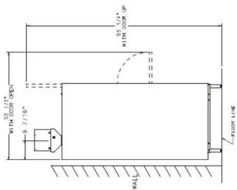
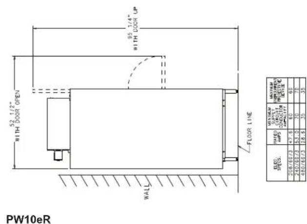
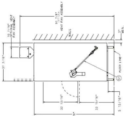
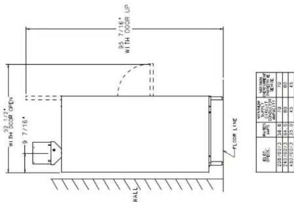
The PW10 and PW20 Prep Washer is the answer to volume utensil washing problems in your kitchen, bakery or supermarket operation. The PW10/20 occupies a minimum amount of floor space (under 48'' × 43'' with door open) and does not require separate dish tables. The upper portion of the door raises, while the lower portion swings out to provide a drain platform. The rack can then be pulled out for easy loading and unloading.
The key pad lets you select a 2-, 4- or 6-minute cycle; each wash cycle is followed by a dwell. After the dwell is a 10 (PW10, PW10eR, PW20) or 12 (PW20eR) second rinse. Advansys models include a 112 to 212 minute condensing time following the rinse cycle. The upper and lower wash arms provide thorough cleaning. Upper and lower rinse arms provide a sanitizing rinse at the end of each cycle.
The PW10/20 is only available with electric tank heat and electric booster is standard. A spray hose and nozzle is provided on the side of the machine.
Features include: sloping strainer system, pumped drain, automatic fill, and rack with inserts for trays. The flat rack can accommodate a 140-quart Hobart mixer bowl.
INSTALLATION
UNPACKING
Immediately after unpacking the PW10/PW20, check for possible shipping damage. If the machine is found to be damaged, save the packaging material and contact the carrier within 5 business days after delivery.
Prior to installation, test the electrical service to ensure that it agrees with the specifications on the data plate located on the bottom right of the upper door.
Unpacking From Pallet
Carefully unpack the machine from the pallet.
- Remove the shipping brackets from the machine/pallet.
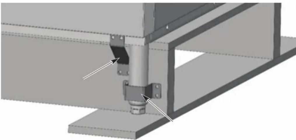
Fig.1
- Remove the bottom pallet boards. This can be done using a pallet jack.
NOTICE Proper care and personal equipment should be used when when handling wood with exposed nails.
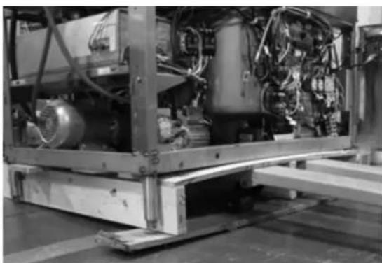
Fig. 2
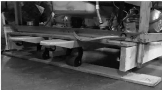
Fig. 3
- Screw out the feet.
- With machine resting on the feet, slide pallet out from underneath the machine.
NOTE: On the PW20 machine the pallet sides might need to be removed to make this easier.
Removing ER Section if Necessary
WARNING Disconnect the electrical power to the machine and follow lockout/tagout procedures. There may be multiple circuits. Be sure all circuits are disconnected.
NOTE: One ER unit is shown in the following steps. If removing both from PW20 Advansys, repeat steps 2 through 10 for each side.
- Disconnect incoming water hose at supply connection.
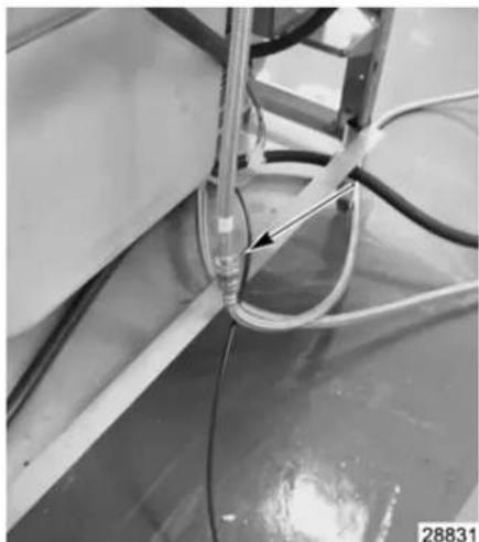
Fig. 4
NOTE: Drain out any excess water in hose.
- Remove upper wash and rinse arms.
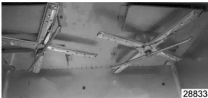
Fig. 5
- Remove baffles. (located under wash and rinse arms).
a. Remove bolt (1).
b. Side baffle to side to free from holding bracket (2) from opposite side of baffle.
c. Remove (Qty 4) nuts (3) that are holding ER assembly from inside wash area.
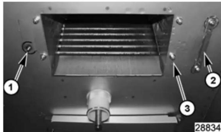
Fig. 6
- Remove shroud.
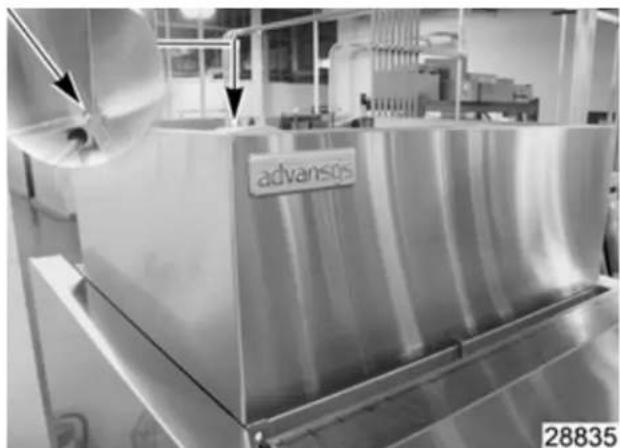
Fig. 7
- Remove door lock assembly cover.
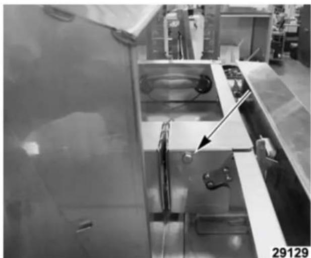
Fig. 8
- Remove motor junction box cover.
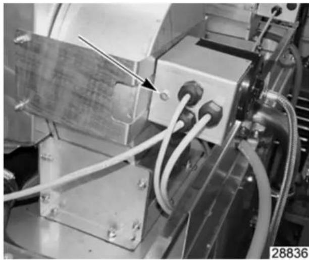
Fig. 9
- Label motor wires for reconnecting later.
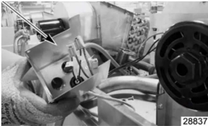
Fig. 10
-
Disconnect motor wires.
-
Disconnect water hoses connected at ER assembly.
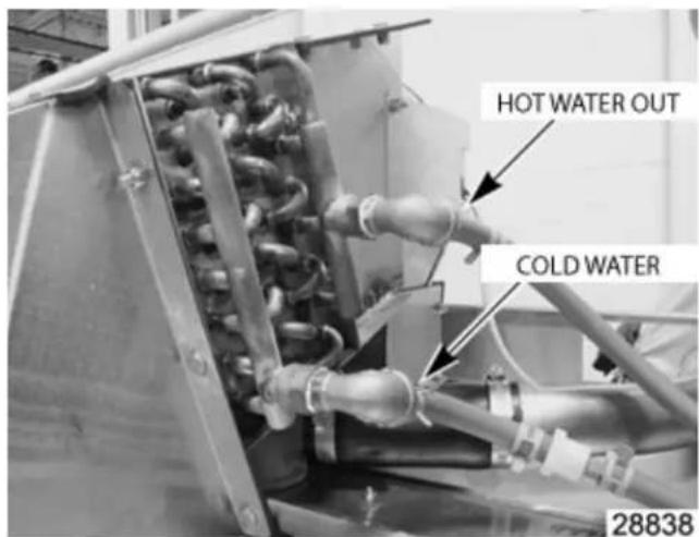
Fig. 11
- Remove (Qty 13) mounting nuts around ER assembly.
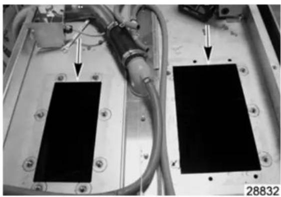
Fig. 12
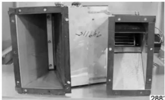
Fig. 13
- Lift ER assembly off of machine.
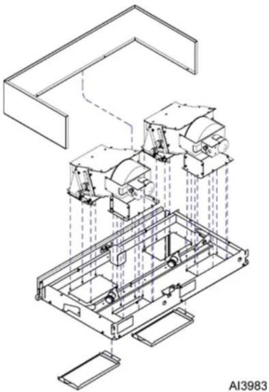
Fig. 14
- Reverse procedure to install.
NOTE: If ER units were removed to get thru a door opening, when re-installing, remove, clean surface, and install new foam tape to the housing to ensure a proper seal.
INSTALLATION CODES
Installation must be in accordance with state and local codes, and the National Electrical Code ANSI/NFPA70 (latest edition). In Canada, the installation code is CSA 22.1 (latest edition).
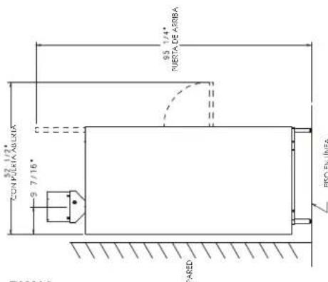
LOCATION
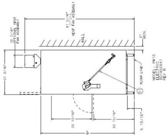
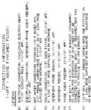
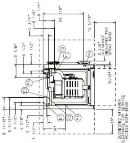
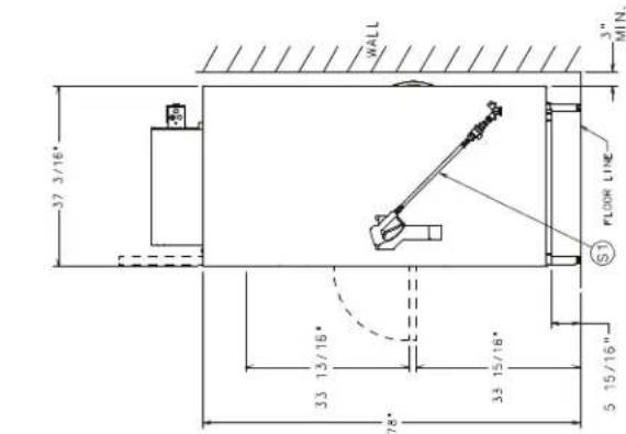
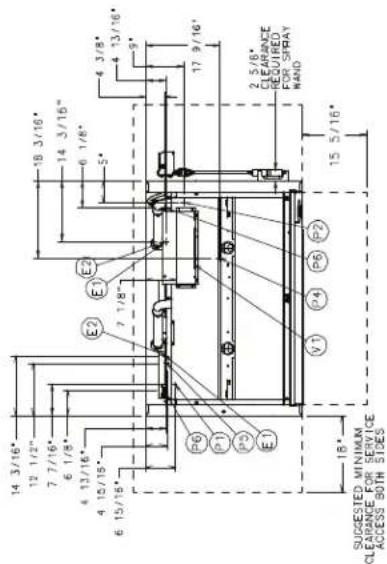
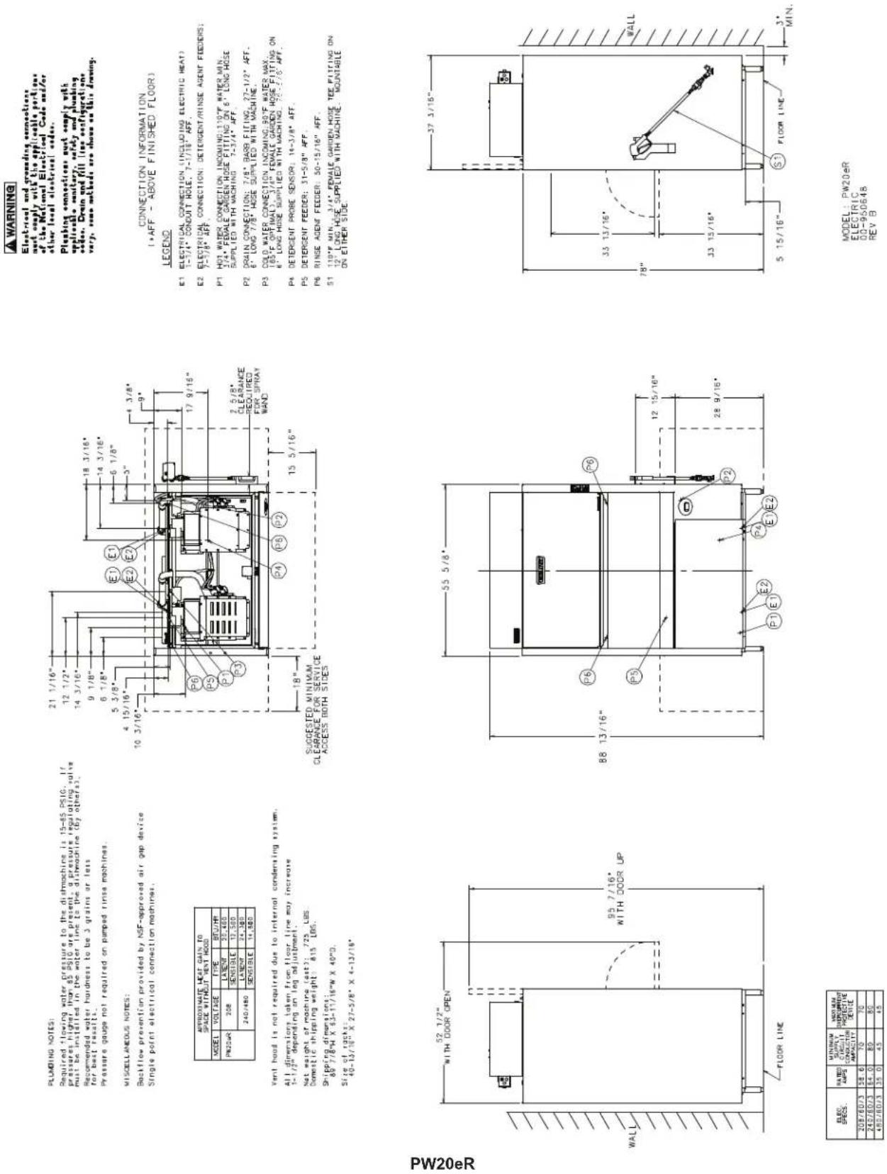
Set the machine in place after the final floor covering is installed. Make sure the machine is level before making any plumbing connections. Allow at least 3" at the rear and 18" at the sides of the machine for service access. Allow 16" in front of the machine for the door to lower and sufficient additional space for the operator to work.
WARNING
Electrical and grounding connections must comply with the applicable portions of the National Electrical Code and/or other law or electrical codes.
Plumbing connections must comply with applicable sanitary, safety and plumbing codes. Drain and fill lines as configuration vary, some methods are above on this drawing.
PLUMBING NOTES:
Required flowing water must be installed in
e recommended water nofor best results .
Pressure gauge not required an pumped piston machines.
MTCELLARE05 NOTES:
Electric power production in the case of DC-ACs with single-pull electrical connection modes
21 dimention taken from floor ring 1 - 1 / 2 depending on lag adjustment.
net weight of machine: 314 LBS
Dampels clothing weight: 367, 185.
Shippinc dimension
PLUMBING NOTES:
Required flowing water must be installed in
e recommended water nofor best results .
Pressure gauge not required
MTCELLANEOUS NOTES:
Single gate electrical core
21 dimention taken from floor ring 1 - 1 / 2 depending on lag adjustment.
nat weight of nothing : 324
Fermentable shipping weight : 1
Shipping dimensions:
PW10
| KILLE SPECS. | PARKIZE AMPS. | MINIMUM CAPACITY CONDITION | MAXIMUM CIRCUITS INTERRUPTIVE BEFORE |
| 208/83/75 | 4.7-6 | 60 | 60 |
| 240/83/75 | 5.3-5 | 70 | 70 |
| 480/83/75 | 28-8 | 35 | 35 |
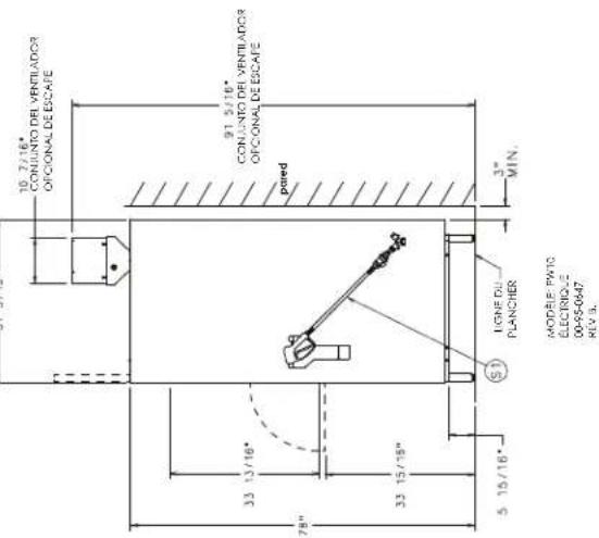
WARNING: Electrical and grounding considerations must comply with the applicable partitions of the National Standard Code and/or other local electrical standards.
Plumbing connections must comply with applicable sanitary, safety and plumbing codes. Drain and fill line configurations vary; some methods are shown on this diet
75-1/4P+3-2-4-1/4P+3+1/4P+3+1/4P+3+1/4P+3+1/4P+3+1/4P+3+1/4P+3+1/4P+3+1/4P+3+1/4P+3+1/4P+3+1/4P+3+1/4P+3+1/4P+3+1/4P+3+1
WARNING
Electrical and grounding connections must supply with the applicable portions of the National Electrical Code and/or other local electrical codes.
Plumbing connections must simply withapplicable accessories , safety and plumbingequipment . Drain and fill line sepiotreatmentvery few methods are shown as this draw
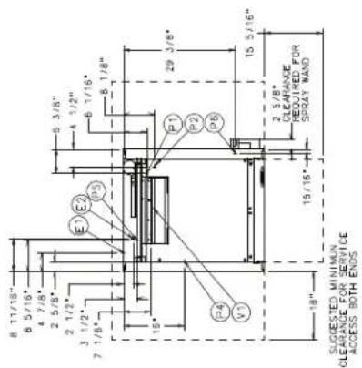
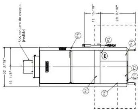
CONNECTION INFORMATION (AFF - ABOVE FINISHED FLOOR)
LEGEND
E1 ELECTRICAL CONNECTION (INCLUDING ELECTRIC HEAT) 1-1/4" CONDUIT ROLE,7-1/16" AFF. E2 ELECTRICAL CONNECTION: DETERGENT/RINSE AGENT FEEDERS; 8-3/16" AFF.
P1 Hot WATER CONNECTION INCOMING: 120^ WATER MIN. 3/4" FEMALE GENDER HOSE FITTLED ON 8" LONG HOSE 6/4" FEMALE GENDER HOSE FITTLED ON 9" LONG HOSE
P2 ORAIN CONNECTION: 3 / 8^ BARB FITTING, 27 - 1 / 2^ APP. 6 LONG 7 / 8^ HOSE SUPPLIED WITH MACHINE.
65° F optimal, 3/4° FEMALE GARDEN HOSE FITTING 6° LONG HOSE SUPPLIED WITH MATCHING 78/72° AFF
PDEGEMPENTFRAEESSMENT:41-11/16"AFFPES DEEMPENT FEDER:31-10/16"AFF.
PINE RINSE AGENT FEDER 52-5716 APF S11 130F MIN.3/4FEMALE GARDEN H
ON EITHER SIDE.
| APPROXIMATE NET GAIN TO SPACE WITHOUT REF NOD | |||
| MODEL | VOLTAGE | TYPE | BF/AMR |
| PW10W | 2.05 | L4TET | 18,200 |
| L4TET | 18,200 | ||
| 240/480 | L4TET | 29,100 | |
| SANSILE | 12,300 | ||
Vent hood is not required due to internal condensing system.
All dimensions taken from floor line may increase 1 - 1 / 2 depending on leg adjustment.
Net weight of machine: S12 LBS. Domestic shipping weight: S75 LBS
Shipping dimensions: 13/14"X 60" X 12"
Size of racks: 23-3/4" x 26-11/19" x 2-1/4"
MODEL: PW10eR
ELECTRIC
00-9305647
REV.B
Required flowing water pressure to the dishimachin is 15-65 PSIc. If pressures higher than 65 PSIc are present, a pressure regulating valve is used to prevent the flow from flowing into the dishimachin.
Recommended water hardness to be 3 grains or lessPressure gauge not required or pumped rinse machines
MISCELLANEOUS NOTES:
Backflow prevention provided by NSF-approved air gap device Single point electrical connection machines.
PLUMING NOTES: Dedined for sale.
pressures higher must be installed
Recommended for best result
Pressure gauge
MISCELLANEOUS, N.
Backflow preven
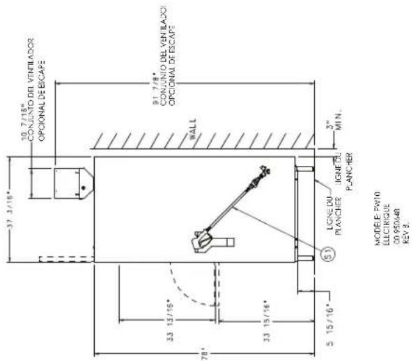
WARNING
Electrical and grounding connections must comply with the applicable portion of the National Electrical Code and/or other local electrical codes.
Plumbing connections are simply with appliable security, safety and plumbing orders. Drain and fill line configurations very, some methods are shown as this dressing.
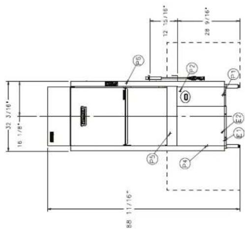
LEGEND
1E ELECTRICAL CONNECTION (INCLUDING ELECTRIC HEAT): 1-1/4" CONDUCTOR HOLE, 7-1/18" AFF.
2E ELECTRICAL CONNECTION: (INTERRUPTIVE/INRSUE AGENT FEEDERS):
7-1/8" AFF
P1 HOT WATER CONNECTION INCOMING:110°F WATER MIN.
2 FEMALE CONNECTOR:11/16" AFF. 3 LONG HEAD SUPPLIED WITH MACHING.7-1/16" AFF.
P2 DRAIN CONNECTION:7/8" BARS FITTING.25-15/16" AFF.
6° LONG 7/8" HEDGE SUPPLIED WITH MASTHINE.
P4 DETERIENT PROGE SENSOR: 14-5/8" AFF.
P5 DETERIENT FEEDER: 31-5/8" AFF.
P5 RINSE AGENT FEEDER:20-13/16"APPV VENT EXIT:4-9/16"EXHIBIT STANDARD TO ALLOW FOR EXPANSION OF AIR (NEED) NOT BE CONNECTED TO EXTERNAL VENT;IF REQUIRED,VENT FAN
Assembly TO PROVE 400 CFM EWAUST.
51 110^ F MIN, 3/4^ FEMALE GARDEN HOSE FEE FITTING ON 12° LONG HOSE SUPPLIED WITH MACHINE. MOUNTABLE ON EITHER SIDE.
PLUMING NOTES:
Required flow pressures high must be installed
Recommended water bar for heat results.
Prepargue gage not required on pamped ringemachins.
MUSCELLANALDUSNOTES:
aee
Single point electrical connection machines
11 dimensions taken from the line 1- 1/2" depending on the adjustment
net weight of machine: $12,105
Dunisic shing weight. 703
Pw20
MODE1:PW20
ELECTRIC
| M10 M100 | M50 M500 | |||
| SAC | PA | PAC | CIG | CIG |
| % of total | |||
| 208/601.3 | 58.6 | 70 | |
| 240/602.3 | 84.0 | 80 | 80 |
| 400/602.3 | 35.0 | 43 | 45 |
WARNING Electrical and grounding connections must comply with applicable portions of the National Electrical Code (NFPA No. 70, CSA 22.1 latest edition) and/or other local electrical codes.
Water Requirements
Proper water quality can improve ware washing performance by reducing spotting, enhancing effectiveness of labor and extending equipment life. Water conditions vary from one location to another. The recommended proper water treatment for effective and efficient use of this equipment will also vary depending on the local water conditions. Ask your municipal water supplier for details about your local water conditions prior to installation.
Recommended water hardness is 3 grains of hardness per gallon or less. Higher hardness may cause excessive formation of lime scale. Water hardness above 3 grains per gallon requires water treatment. Water treatment has been shown to reduce costs associated with machine cleaning, reduce deliming of the dishwasher, and reduce detergent usage in the dishwasher. Chlorides must not exceed 50~ppm .
NOTICE High iron levels in the water supply can cause staining and may require an iron filter. High chloride levels in the water supply can cause pitting and may require a chloride removal system. Contact your local water treatment professional for proper water treatment.
Sediment may require a particulate filter. Dissolved solids may require water treatment such as a water softener, reverse osmosis system, etc. Contact your local water treatment professional for proper water treatment.
If an inspection of the dishwasher or booster heater reveals lime buildup after the equipment has been in service, water treatment is recommended. If a water softener is already in place, ensure there is a sufficient level of salt. Contact your local Hobart Service office for specific recommendations.
Water Supply Connection
The water supply line should be a 34 male garden hose (supplied by others).
The plumber connecting this machine is responsible for making certain that water lines are THOROUGHLY FLUSHED OUT BEFORE connecting to the dishwasher. This "flush-out" is necessary to remove all foreign matter, such as chips (resulting from cutting or threading of pipes) pipe joint compound from the lines; or, if soldered fittings are used, bits of solder or cuttings from the tubing. Debris, if not removed, may lodge in the dishwasher's plumbing components and render them inoperative. Manual valves or solenoid valves fouled by foreign matter and any expenses resulting from this fouling are NOT the responsibility of the manufacturer and associated repair costs are not covered under warranty.
Water supply requirements are as follows:
WATER SUPPLY REQUIREMENTS
| Model Supply | ly Temperature | |
| PW10 Hot Water | 110°F Minimum | |
| PW10eR Cold W | ater 55°F Minimum, 80°F Maximum | |
| Hot Water 110°F Minimum | ||
| PW20 Hot Water | 110°F Minimum | |
| PW20eR Cold W | ater 55°F Minimum, 80°F Maximum | |
| Hot Water 110°F Minimum |
PW10eR and PW20eR models require both a cold water supply connection and a hot water supply connection.
NOTICE On PW10eR and PW20eR installations, the cold water supply must not exceed 80^ (27^) for proper operation. Optimal results are obtained when cold water supply temperature is below 65^ (18^) . For best results, it may be necessary to use 12 pipe for cold water pipe size and minimize the distance between the dishwasher and the entrance into the building. Pipe insulation will also improve results.
If cold water supply temperature is consistently above 80^ (27^) or if excessive water vapor or steam is entering the room after the condensing cycle is complete, contact Hobart Service to increase condensing time.
Required flowing water pressure to the dishmachine is 15-65 PSIG. If pressures higher than 65 PSIG are present, a pressure regulating valve must be installed in the water line to the dishmachine (by others). If flowing pressure is less than 15 psi, improper machine operation may result. All PW models are equipped with a pumped rinse system; therefore, a water pressure gauge is not required and is not supplied with the machine.
NOTICE The water pressure regulator must have a relief bypass. Failure to use the proper type of pressure regulator may result in damage to the unit.
A manual shutoff valve (not supplied) should be installed upstream of the fill hose to accommodate servicing the machine.
It is recommended that a line strainer (not supplied) be installed in the supply line between the manual shutoff valve (not supplied) and the connection point on the machine. Make plumbing connections with 12 minimum copper piping OD (34) recommended), with a 34 male garden hose fitting (not supplied). See installation diagrams, pages 11-14.
Plumbing Connections
WARNING Plumbing connections must comply with applicable sanitary, safety, and plumbing codes.
Drain
A drain hose, 7/8" inside diameter and 6' long, is provided. This should be securely plumbed into a drain. Use care not to kink hose. See installation diagrams, pages 11-14. Drain must have a minimum flow capacity of 18 gallons per minute for PW10/ PW10eR and 26 gallons per minute for PW20/PW20eR.
Venting Requirements (PW10 / PW20)
Type I or type II canopy hoods are recommended. Hoods must be installed according to the manufacturer's instructions. Make-up air must be provided so that the exhaust flow rate results in a negative building pressure in the room where the unit is located (more exhaust air than outside air). Factory-built hoods not tested to UL standard 710 and custom-built hoods must comply with the following specifications: Stainless steel should have a minimum thickness of 0.037 in. (0.94mm) [No. 20 Gauge] or copper sheet weighing at least 24 ounces per square foot (7Kg / m2) ; the hood must be secured in place by noncombustible supports and must meet the RATE of EXHAUST FLOW CALCULATIONS.
NOTICE Make sure the installation meets the local code for your area.
Rate of Exhaust Flow Calculations (FIG. 14)
Based on the 2015 International Mechanical Code.
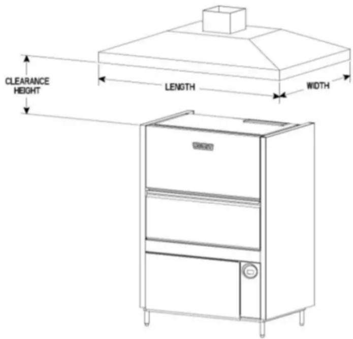
Fig. 15
Canopy Size and Location
The inside lower edge of canopy-type type I and II commercial hoods shall overhang or extend a horizontal distance of not less than 6 inches (152 mm) beyond the edge of the top horizontal surface of the appliance on all open sides. The vertical distance between the front lower lip of the hood and such surface shall not exceed 4 feet (1219 mm) with a minimum of 1 foot (305 mm).
18" min overhang of the front opening.
The RATE of air flow required for a vent hood is a minimum of 100 CFM per linear foot of hood length.
Rate of Exhaust Flow Calculations
Based on the 2015 International Mechanical Code.
The minimum net airflow for Type II hoods used for dishwashing appliances shall be 100 cfm per linear foot of hood length. The net quantity of exhaust air shall be calculated by subtracting any airflow supplied directly to a hood cavity form the total exhaust flow rate of a hood.
Models PW10eR and PW20eR do not require a Type II vent hood. According to 507.3 of the 2015 IMC, Type II hoods are not required where the heat and moisture loads is incorporated in the HVAC system design. See Table A for heat dissipation or heat gain to space.
Table A
| HEAT DISSIPATION | ||||
| Model Voltage | Latent Heat (BTU/HR) | Sensible Heat (BTU/HR) | ||
| PW10 208V 13 | 600 6,000 | |||
| PW10 240V / 4 | 30V 16,800 7,300 | |||
| PW10eR 208V | 16,200 10,000 | |||
| PW10eR 240V | 480V 20,100 12 | 300 | ||
| PW20 208V 17 | 100 7,500 | |||
| PW20 240V / 4 | 80V 20,400 8,900 | |||
| PW20eR 208V | 20,400 12,500 | |||
| PW20eR 240V | 480V 24,300 14 | 800 | ||
Chemical Feeder Installations
This machine must be operated with an automatic detergent feeder, including a visual means to verify that detergents are delivered or a visual or audible alarm to signal if detergents are not available for delivery to the washing system. Chemical feeders are supplied by others. For electrical connection, refer to Equipment Connections, page 21.
Detergent Feeder (Optional By Others)
If installing a detergent feeder (by others), remove cap to expose 7/8'' diameter hole at rear of machine.
Rinse Agent Feeder (Optional By Others)
If a rinse agent feeder (by others) is being installed, remove the 1/8" NPT pipe plug(s) to access the tapped hole in the rinse tee on the right side of the machine (PW10/PW10eR) and on the back of the machine (PW20/PW20eR). There are 2 rinse tees for the PW20/PR20eR machines.
Deline Feeder (standard) on Advansys models only (PW10eR/ PW20eR)
A delime feeder with tubing and standpipe is provided to automatically dispense delime agent when needed.
Vent Exit (PW10 / PW20)
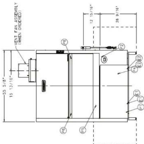
A vent exit (4-9/16 " x 17-3/8") is provided in the top of the machine to allow for expansion of air. It must not be directly connected to an external vent.
Vent Fan Control (Standard); Power Vent Fan (Optional) PW10/PW20
The Vent Fan Control provides switching for a vent fan (by others). The vent hood comes on when the PW10/20 is on and goes off when the PW10/20 is off. The Power Vent Fan option exhausts moist air from the chamber after the rinse cycle is finished. The Power Vent fan may be selected to operate for 40, 60 or 80 seconds. The Power Vent Fan kit (field installed only) extends upward 1214 above the vent exit (13 5/16" above the top of the wash chamber) and terminates in a round duct connection for a 101/4" O.D. duct.
Install power vent fan kit using a maximum 60 ft of 10^ diameter straight duct; or, 50 ft straight and two (2) 90^ elbows, or equivalent. Distances greater than the stated maximum lengths may reduce venting efficiency.
ELECTRICAL CONNECTION(S)

WARNING Electrical and grounding connections must comply with applicable portions of the National Electrical Code (NFPA No. 70, latest edition) and/or other local electrical codes.
WARNING Disconnect the electrical power to the machine and follow lockout/tagout procedures. There may be multiple circuits. Be sure all circuits are disconnected.
Connect incoming power to the control box in accordance with the wiring diagram located on the back of the front trim panel.
| ELECTRICAL DATA | ||
| PW10 / PW10eR (Single Point Connection) | ||
| Volts/Hz/ph Rated Amps Circuit Size* | Amps | |
| 208/240/60/3 4 | 7.6 / 53.0 60 / 70 | |
| 480/60/3 28.6 | 35 | |
| PW20 / PW20eR (Single Point Connection) | ||
| Volts/Hz/ph Rated Amps Circuit Size* | Amps | |
| 208/240/60/3 5 | 8.6 / 64.0 70 / 80 | |
| 480/60/3 35.0 | 45 | |
- Minimum Circuit Size / Maximum Protective Device (Amps) compiled in accordance with the National Electrical Code (NFPA 70), latest edition.
** For supply connection, use wires suitable for at least 90^ or equivalent
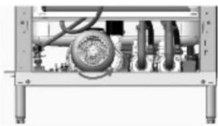
Rotation of Pump Motor(s)
Before using the machine, check the pump motor rotation to be sure it is rotating in the right direction.
PW10 / PW10eR
From the front of the machine, the motor should rotate clockwise. Looking from the rear of the machine, the correct rotation is counterclockwise. Inspection is easiest from the rear of the machine using a flashlight and mirror to check the motor fan in the rear. Be aware that the mirror will reverse the perceived direction.
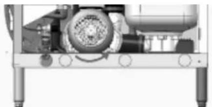
PW10 (Rear View)
Fig. 16
PW20 / PW20eR
Pump motor 1 - Looking from the right side of the machine, the correct rotation is counterclockwise. Inspection is easiest from the right side using a flashlight to check the motor fan on the rear of the motor.
Pump motor 2 - Looking from the left side of the machine, the correct rotation is counterclockwise. Inspection is easiest from the left side using a flashlight to check the motor fan on the rear of the motor.
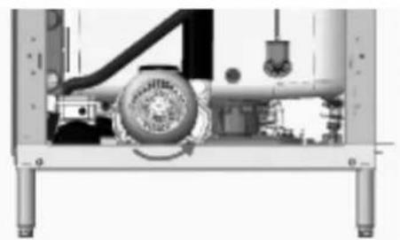
PW20 (right view) PW20 (left view)

Fig. 17
If the pump motor(s) is/are rotating in the wrong direction, follow this procedure.
WARNING Disconnect the electrical power to the machine and follow lockout/tagout procedures. There may be multiple circuits. Be sure all circuits are disconnected.
Reverse any two of the three incoming line wires (not the ground wire). Reconnect and recheck rotation of pump motor.
EQUIPMENT CONNECTIONS

WARNING Electrical and grounding connections must comply with applicable portions of the National Electrical Code (NFPA No. 70, latest edition) and/or other local electrical codes.
WARNING Disconnect the electrical power to the machine and follow lockout/tagout procedures. There may be multiple circuits. Be sure all circuits are disconnected.
Vent Fan Control
The vent fan control feature is standard on PW10 and PW20 models. This feature is not available on PW10eR and PW20eR models. The vent fan control relay provides switch contacts only and does not provide power to the vent fan motor. The rating for a vent fan control relay connected to terminals VFC1 and VFC2 is 1.5 amps at supply voltage. When the prepwasher is connected to the vent fan, the vent fan is switched on when the prepwasher is on, and off when the prepwasher is off.
Detergent Feeder
The maximum rating for a detergent dispenser connected to DPS1 and DPS2 is 1.5 amps at line voltage. Refer to Chemical Feeder Installations, page 18.
Rinse Aid Feeder
The maximum rating for a rinse aid dispenser connected to RPS1 and RPS2 is 1.5 amps at line voltage. Refer to Chemical Feeder Installations, page 18.
OPERATION
CONTROLS
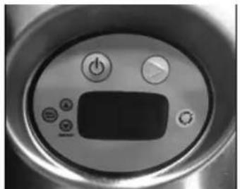
Fig. 18
Operating the PW Prep Washer
| DO THIS DISPLAY | SHOWS REMARKS | |
| Press ON Model number | Dishwasher performs self- | check. This takes 5 seconds. |
| FILL and fill icon lit; sump temperature displayed when machine is filling.WARMING UP and warming up icon are displayed when booster is preheating on models. This preheat could take up to 25 minutes. | Dishwasher fills with water.If door is opened during fill cycle, fill will stop. After door is closed, the process continues where it stopped. | |
| During fill, sump temperature is displayed. | When filled, machine will maintain an idle state. Heat is maintained in both sump and booster. | |
| Open door; slide rack out to load ware. When loading is complete, slide rack into dishwasher.Close door. | READY lit and sump temperature displayed. | Detergent contacts will be activated during wash cycle.Rinse contacts turned on during rinse cycle for external dispenser. |
| Press WASH (Green Arrow). | WASH and wash icon lit;sump temperature displayed during wash cycle.RINSE and rinse icon lit;rinse temperature displayed during rinse cycle.CONDENSE and condense icon lit (Advansys models only).EXHAUST (base models with Vent Fan Control only). | Machine initiates a wash and rinse cycle.If door is opened during wash, rinse, or drain cycle, cycle will continue at point where door was opened upon closing door.If POWER is pressed during cycle, machine will drain and shut down |
| DO THIS DISPLAY SHOWS REMARKS | ||
| When cycle is complete, reload machine for next wash/rinse cycle; or, if not in use, machine will maintain idle mode. | READY lit and sump temperature displayed. | Machine will drain and shut down if the four hour idle shut-down time is reached. |
| At the end of the day, press POWER. | DRAIN and SHUTDOWN IN PROGRESS are displayed; then the machine shuts down. | When POWER key is pressed, machine will drain and shut down. |
SELECT WASH CYCLE and press START
| CYCLE DESCRT | PTION |
| 2 A 2-minute | wash cycle is followed by a 10 or 12-second fresh water rinse (Advansys models have 99-190 second condensing cycle). |
| 4 A 4-minute | wash cycle is followed by a 10 or 12-second fresh water rinse. (Advansys models have 99-190 second condensing cycle). |
| 6 A 6-minute | wash cycle is followed by a 10 or 12-second fresh water rinse. (Advansys models have 99-190 second condensing cycle). |
| All rinse cycles are followed by a 5 second pause. | |
Minimum Wash tank temperature is 150^ . Minimum Rinse temperature is 180^ .
PROGRAMMING
Manager Mode Programming
The PW series prep washer's microprocessor allows customization options for machine operation. To activate or change these features, the programming edit mode must be entered.
The manager programming mode requires a MANAGER CODE to be entered to access the options listed in the PARAMETER MENU. The manager codes is 1001.
PW PW Manager Mode Programming Card
advansys
CHANGING PARAMETERS ENTER MANAGER SECURITY CODE: 1001

→MANAGER MENU → ENY → ENTER SECURITY CODE → (for 1)

(for 0) (for 0) (for 1) Edit Parameters
CHANGING PARAMETERS IS REQUIRED TO CHANGE ALL CODES BELOW
DELIME enables or disables the delime reminder alert.

→ until DELIME → ENT → to enable or disable → ENT

ENT until EXIT ENT
LOW TEMP ALARMS enables or disables alert indicating that the final rinse temperature has been below the minimum temperature for a period of time.

→ until LOW TEMP ALARMS → ENT1 → to enable or disable → ENT1

ENT until EXIT
END CYCLE AUDIO ALERT enable or disable the unit creating an audio alert at the end of each wash cycle.

→ until END CYCLE AUDIO ALERT → to enable or disable →

until EXIT MENU until EXIT
TEMPERATURE UNITS allows the choice of Fahrenheit or Celsius.

→ until TEMPERATURE UNITS → ENT to choose Fahrenheit or Celsius

OR until EXIT MENU until EXIT
DIRTY WATER INDICATOR disables or gives a choice of how many cycles the machine will run between dirty water alert and refresh cycles.

→ until DIRTY WATER INDICATOR → to Disable, 20 cycles, 40 cycles.
or 60 cycles → ENT OR ∇ → until EXIT MENU → ENT → until EXIT → ENT
ENERGY SAVER MODE disables or gives choice of how many hours before the unit will stay on before entering energy saving mode.

→ until ENERGY SAVING MODE → ENIT to Disabled, 1 Hour, 2 Hours, or 3 Hours

OR until EXIT MENU ENT until EXIT ENT

Programming Instructions
All customization is performed through the on-screen menu using the UP arrow, MENU/DOWN arrow, and ENT keys located on the keypad on the lower right of the machine (Fig. 4).
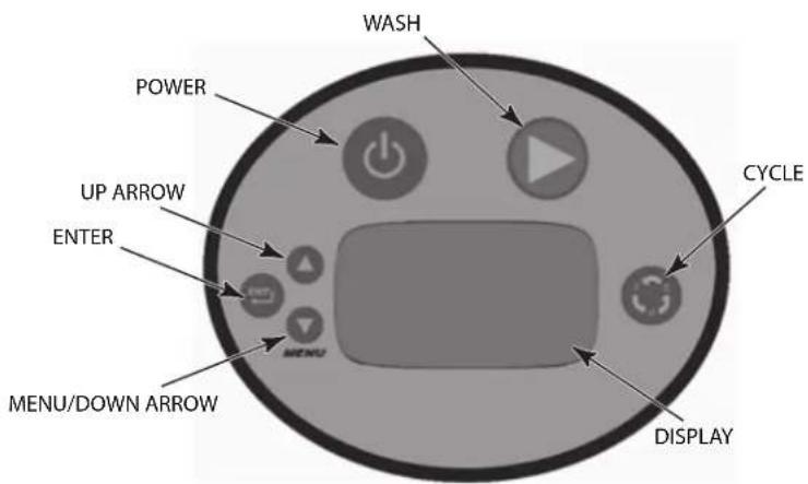
Fig. 19
Menu Display Prompts
The following prompts are used inside the menus:
- The UP arrow and MENU/DOWN arrow keys are used to change parameter values and to navigate the menu.
The ENT key is used to accept a value, to perform a specific action, or to enter a submenu.
On PW10eR and PW20eR Advansys models, the door is locked and must remain closed until the condensing cycle is completed. During the condense cycle a countdown icon shows the remaining cycle time. When the cycle is finished and the condense icon disappears and the condensing cycle light turns off and the door is unlocked. Open the door and pull out the rack to remove the clean ware. Load soiled ware onto rack and push rack into the machine. Close the door.

Recommended Condense Time (Based on Incoming Water Temperature)
| Incoming Water Temp °F (°C) | PW10eR PW20eR | |||||
| Rinse Time (Sec.) | Condense Time (Sec.) | Racks per Hour (2 min. cycle) | Rinse Time (Sec.) | Condense Time (Sec.) | Racks per Hour (2 min. cycle) | |
| 60 (16) – 64 (18) | 10 99 1 | 3 12 98 13 | ||||
| 64 (18) – 72 (22) | 12 119 | 2 14 114 12 | ||||
| 72 (22) – 80 (27) | 14 139 | 11 16 131 11 | ||||
| 80+ (27+) 16 | 58 10 | 18 147 10 | ||||
For Advansys models only - If excessive amounts of steam or water vapor exit the machine after condensing cycle light goes out and door is opened, incoming cold water temperature may be too high.
Contact Hobart Service to adjust the rinse and condense times according to the adjustment table. Increasing cycle time will increase water consumption and decrease the racks per hour, but should reduce the water vapor entering the room.
General Operating Instructions
Keep the prep washer clean to provide best results. Do not allow foreign objects to enter the unit, especially metallic contaminants.
Do not wash aluminum utensils in the prep washer. The caustic detergent and high water temperature will cause aluminum oxide formation (black). Copper utensils may require polishing to remove oxide formation after exposure to utensil washer cleaning for a period of time. Stainless steel utensils should clean quickly and easily if the food soil is not baked on.
It may be necessary to scrub or prewash some hard-to-remove substances which may not come clean in the prep washer with even a 6-minute washing. For stubborn food soil, a plastic scraper, plastic abrasive pad, nylon bristle brush or sponge with abrasive surface (Scotch Brite) may be used before washing in the prep washer. Never use steel wool on ware to be loaded into the prep washer. Use only products formulated to be safe on stainless steel. Do not use deliming agent on outside of machine. Rinse items thoroughly after scrubbing to remove metallic debris.
CLEANING

WARNING Disconnect the electrical power to the machine and follow lockout/tagout procedures. There may be multiple circuits. Be sure all circuits are disconnected.
The prep washer must be thoroughly cleaned at the end of each working shift. Use only product formulated to be safe on stainless steel. Never use steel wool to clean machine surfaces.
- Spray down inside of machine with wand (Fig. 20).
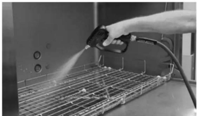
Fig. 20
- Press POWER. The machine will drain. (Fig. 7).
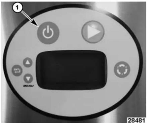
Fig. 21
NOTE: Shutting off the machine causes a full automatic drain, which takes about 3 minutes for a PW10 and about 3-1/2 minutes for a PW20.
-
Remove tray and racks.
-
The wash and rinse arms are easily removed for cleaning. Make sure that the wash and rinse arms rotate freely and are free of any obstructions. If any obstructions are present, remove the wash and rinse arms. Clean the wash and rinse arms under running water in a sink.
a. To remove upper rinse arm and wash arm (Fig. 22):
i. Unscrew the rinse arm by loosening the tabbed ring at top of rinse arm
ii. Remove both Rinse and Wash arms at the same time, being careful not to drop these arms.
iii. Reverse the process to replace. Spin arms to make sure they spin freely.
b. To remove lower rinse arm and wash arm (Fig.23).
i. Unscrew the rinse arm by loosening the tabbed ring at bottom of rinse arm.
ii. Remove both Rinse and Wash arms at the same time, being careful not to drop these arms.
iii. Reverse the process to replace. Spin arms to make sure they spin freely.
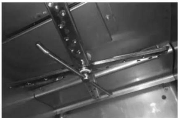
Fig. 22
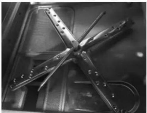
Fig. 23
-
Remove the strainer pans and strainer basket (Fig. 5), and empty into a waste disposer or garbage container. Wash and rinse strainer pans and strainer basket thoroughly. Do not bang strainers pan or basket on tables to remove food soil
-
Spray down sump (Fig. 24).
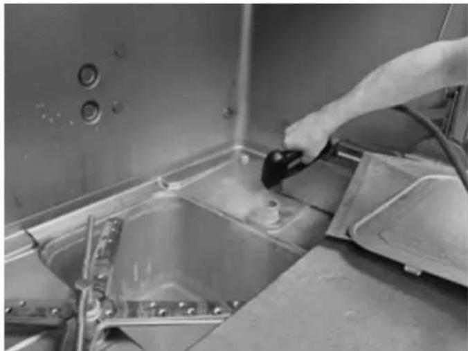
Fig. 24
- Turn machine back on for 2 minutes to fill.
- Turn off machine again to flush sump.
- With a damp cloth, wipe the interior and exterior of the machine. DO NOT use steel wool. Remove any remaining debris with a mild cleanser formulated for stainless steel and a soft cloth or brush.
- Carefully reinstall the strainer pans and strainer basket.
- Use a soft, damp cloth or sponge and mild cleanser to clean the control keypad and display. DO NOT use abrasive or harsh cleaners or scouring pads.
- Leave the doors open to allow the interior to dry and air out.
NOTICE Do not use spray hose to spray down exterior of machine.
In addition to normal cleaning, the baffles, located on the upper chamber on the inside of the machine, may need periodic cleaning. Note that the PW20eR will have two sets of baffles.

WARNING Disconnect the electrical power to the machine and follow lockout/tagout procedures. There may be multiple circuits. Be sure all circuits are disconnected.
- Loosen and remove the nut from the front baffle(s) and remove baffle(s) by sliding the tab out of the retainer.
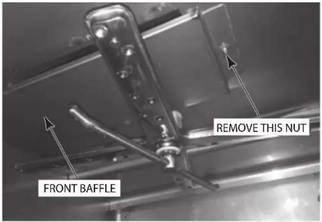
Fig. 25
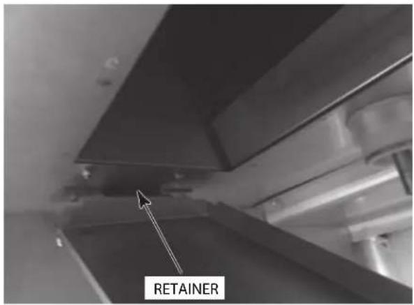
Fig. 26
- Debris may collect on the top surface of baffles and should be washed in a sink with mild detergent and rinsed.
- Replace all removed parts.
- Leave machine door open to allow interior to air out and dry.
DO'S AND DON'TS FOR YOUR NEW HOBART DISHWASHER
DO ensure proper water hardness of 3 grains or less per gallon. Total Dissolved Solids (TDS) must be 50~ppm or greater. Chlorides must not exceed 50~ppm .
DO pre-s scrap dishes thoroughly.
DO use only detergents recommended by your chemical professional.
DO, at the end of the day, complete a manual cleaning cycle as needed; thoroughly cleanse the machine, rinse, and dry (leave doors open).
DO closely follow the machine's deliming schedule.
DO use only products formulated to be safe on stainless steel.
DO NOT use detergents formulated for residential dishwashers.
DO NOT allow food soil to accumulate on the tank bottom.
DO NOT exceed chemical manufacturer's recommended concentrations for detergent, rinse aid or lime scale remover.
DO NOT use steel wool to clean ware or dishwasher surface.
DO NOT allow foreign objects to enter the unit, especially metallic contaminants.
NOTE: Failure to follow use, care, and maintenance instructions may void your Hobart dishwasher warranty.
MAINTENANCE
MOTOR
The motor has permanently sealed bearings and requires no lubrication.
WASH AND RINSE ARMS
All wash arms and rinse arms should turn freely and continue turning for a few seconds after being whirled by hand. To check, DISCONNECTELECTRIC POWER SUPPLY, rotate arms and remove any obstructions causing improper operation. Refer to CLEANING THE PREP WASHER on pages 27-31.
If the strainer pans and strainer basket are not properly in place, obstructions (such as food particles or toothpicks) may clog the wash arm nozzles.
DELIMING
WARNING Deliming solution must not come in contact with bleach or rinse solution containing bleach. Mixing may cause hazardous gas to form. This entire procedure must be followed step-by-step for safe and satisfactory results.
The dishwasher should be delimed on a regular basis as required. How often depends on the mineral content of the water. Deliming should be done when you can see clear signs of lime deposits (a white chalky substance) on the inside walls, on the wash and rinse arms and tank heater. Inspect the machine interior for lime deposits. If deliming is necessary, a deliming agent (such as Lime-A-Way® or LSR®) should be used for best results.
All Prep washers are equipped with an automatic delime cycle reminder. It is recommended that deliming be done when DELIME RECOMMENDED is lit. PW10eR and PW20eR models are equipped with an internal delime pump which will automatically pump the required amount of deliming agent into the unit. All PW10eR/PR20eR models are equipped with an automatic deliming system. At installation, a qualified Hobart Service technician or your chemical supplier must adjust the total water hardness setting to properly set the delime intervals.
Remove the deliming agent bottle cap and put the black delivery tube in the container. Be sure to push the delivery tub standpipe completely to the bottom of the container. Check to make sure there are no obstructions or kinks in the delivery tube.
After the preprogrammed number of cycles has expired, the control will indicate the delime request by displaying DELIME RECOMMENDED and will prompt 'would you like to delime now?' . You must enter Yes' or No' to proceed with a delime cycle or to continue with normal machine operation. If No' is selected, the machine will continue to notify the operator at each start-up and power down until the delime cycle is completed. To delime the unit.
- Press the MENU/DOWN Arrow key until the > symbol is shown to the left of 'YES' and press the ENT key.
- Remove rack from the machine.
- Remove strainers from the machine and clean. Replace strainers and rack and close door.
- On PW10er/PW20eR machines, ensure delimer chemical container is not empty. Be sure to push the delivery tube standpipe completely to the bottom of the container. Check to make sure there are no obstructions or kinks in the delivery tube.
- Press ENT key to enter the delime mode. The machine will drain and refill with fresh water.
- On PW10/PW20 machines, after the deliming agent has been added, close the door. Press the ENT key to continue the cycle. The machine will enter the wash mode for about 25 minutes, then will begin two rinse and drain operations. Total time to complete the delime operation will be about 45 minutes. ON PW10eR/ PW20eR machines, the unit will automatically enter the wash mode for about 40 minutes, then will begin several rinse and drain operations after the fill cycle is complete. Total time to complete the delime operation will be about 1 hour 40 minutes.
- After deliming operation is completed, the machine will shut down.
- Inspect the interior of the machine for lime deposits. If necessary, another delime cycle can be initiated by entering Manager Programming Mode.
NOTICE Do not allow deliming agent to remain in the machine longer than recommended by the deliming agent manufacturer. After deliming, run the machine through two 6-minute cycles with no utensils in order to rinse and flush machine interior.
TROUBLESHOOTING
| SYMPTOM POSSIBLE | CAUSE |
| Utensils spotted or not clean | Overloaded rack. Low water level. Water conditions: — Incorrect rinse water temperature. Refer to WATER SUPPLY CONNECTION, page 15. — Excessive water hardness may indicate that a water softener is needed. — Incorrect detergent type or concentration for water conditions. — Incorrect rinse additive for water conditions. Inadequate rinse. — Dirty line strainer causing reduced water flow. Turn off water supply. Remove fill hose and check strainer. Withdraw and clean screen. Reassemble. — Excessive mineral deposits throughout wash and rinse system. Deliming may be necessary. Check water level in tank. The machine won't clean well if there isn't enough water for the pump to maintain adequate wash pressure. Loss of water pressure due to pump obstruction. — DISCONNECT ELECTRIC POWER SUPPLY. Drain tank and check for obstruction at the strainers, basket and pump intake. Insufficient detergent dispensing. — Check supply or detergent supplier. Excessive mineral deposits throughout wash and rinse system. — Deliming may be necessary. — Excessive water hardness may indicate that a water softener is needed. Prep washer was not cleaned properly. Refer to CLEANING THE PREP WASHER. pages 27-31. Wash arm blocked with debris. Refer to WASH AND RINSE ARMS, page 32 |
| Machine won't operate | Fuse blown or circuit breaker tripped. Check water level in tank. |
| Leaking valves Solenoid | valves. — Contact service. — Check valve on spray hose — Foreign material preventing proper valve operation. A critical period is soon after installation when pipe compound or metal shavings may lodge at the valve seat. |
| No wash tank heat | The low water detector will shut off heat if water level is too low. — Check water level. • Fuse blown or circuit breaker tripped. • Heater failure • Overtemperature protector tripped — Contact service. |
| No fill or slow fill | Dirty line strainer causing reduced water flow. — Turn off water supply. Disconnect fill hose and remove strainer. Clean screen. Reassemble. |
SERVICE
Contact your Hobart service office for any repairs or adjustments needed on this equipment. Long-term service contracts are available on this and other Hobart products.
TABLE DES MATIÈRES
GENERAL 4
INSTALLATION 4
DEBALLAGE 5
Retirer la machine de la pallette 6
ploosymptotic of the 1980s
PW10
| SPEC.ELEC. | En amperios de potencia nominal | REQUISOS DE INTENSITY Minima del circuito POTENCY | INTENSITY DE CIRCUITODE LOS REQUISITOSTE BAJA POTENCIA |
| 268/60/3 | 47.6 60 60 | ||
| 240/60/3 | 53.0 70 70 | ||
| 480/60/3 | 58.6 35 35 |
PW10
NOTAS DE CANERLAS:
P-350/SAH/SHM/12/16-24
P-351/SEH/SHM/12/17-24
Noun (nominative in association of Viti, seconium); Noun (nominative in conjunction with VB/INLANCE EXCEPTOR para: propionic acid at 400°C).
- 51.1.1.10, 51.1.1.11, 51.1.1.12, 51.1.1.13, 51.1.1.14, 51.1.1.15, 51.1.1.16, 51.1.1.17, 51.1.1.18, 51.1.1.20, 51.1.20, 51.1.20, 51.1.20, 51.1.20, 51.1.20, 51.1.20, 51.1.20, 51.1.20, 51.1.20, 51.1.20, 51.1.20, 5
NOTAS DE CANERIAS:
La presián requernda para el ljoa de aguc hacia el avovjllas es oe 15 o 65 P5IG. Si je
observed one presenior of a 51sIG,se dede tldie and vallois regu (ne de gaug hocci et iayvagillons (suministrado por os; proevoedores).
sreccimnncnncnncnncnncnncnncnncnncnnnncnncnncnncnncnncnncnncnncnncnncnncnncnncnncnncnncnncnncnncnncnncnncnncnncnncnncnncnncnncnncnncnncnncnncnncnncnncnncnncnncnncnncnncnncnncnncnccnnnnnnnnnnnnnnnnnnnnnnnnnnnnnnnnnnnnnnnnnnnnnnnnnnnnnnnnnnnnnnnnnnnnnnnnnnnnnnnnnnnnnnnnnnnnnnnnnnnnnnnnnnnnnnnnnnnnnnnnnn
rose agnate nendre pae el apy
NOTAS VARIAS:
| APPROXIMADO DE CALOR A LA GANANCIA DEL ESPACIO SIN comaça de ventilación | |||
| MODELO | EVOLUJE | TIPO | |
| PW10eR | 208 | LATENT | 20 400 |
| SENSIBLE | 12 500 | ||
| 240/480 | LATENT | 24 300 | |
| SENSIBLE | 14 800 | ||
WATER SUPPLY REQUIREMENTS
| Modelo Sum | inistro Temperatura | |
| PW10 Agua caliente 110°F (43°C)小時 | ||
| PW10eR Agua frá | a 55°F (13°C)小時, 80°F(27°C) máximo | |
| Agua caliente 110°F | (43oC)小時 | |
| PW20 Agua caliente 110°F (43oC)小時 | ||
| PW20eR Agua frá | a 55°F (13°C)小時, 80°F(27°C)(Maximo | |
| Agua caliente 110°F | (43oC)小時 |