PCE700 - Saw Porter-Cable - Free user manual and instructions
Find the device manual for free PCE700 Porter-Cable in PDF.

User questions about PCE700 Porter-Cable
0 question about this device. Answer the ones you know or ask your own.
Ask a new question about this device
Download the instructions for your Saw in PDF format for free! Find your manual PCE700 - Porter-Cable and take your electronic device back in hand. On this page are published all the documents necessary for the use of your device. PCE700 by Porter-Cable.
USER MANUAL PCE700 Porter-Cable
14 inch (355mm) Chop saw
Scie fendeuse de 355 mm (14 po)
Serra Multi-Corte de Metais de 14 pulg. (355mm)
www.portercable.com
Thank you for choosing PORTER-CABLE! To register your new product, go to: www.portercable.com/ServiceAndSupport/ProductRegistration.aspx
It is important for you to read and understand this manual. The information it contains relates to protecting YOUR SAFETY and PREVENTING PROBLEMS. The symbols below are used to help you recognize this information.
DANGER: Indicates an imminently hazardous situation which, if not avoided, will result in death or serious injury.
WARNING: Indicates a potentially hazardous situation which, if not avoided, could result in death or serious injury.
CAUTION: Indicates a potentially hazardous situation which, if not avoided, may result in minor or moderate injury.
NOTICE: Used without the safety alert symbol indicates potentially hazardous situation which, if not avoided, may result in property damage.
Important Safety Instructions
WARNING: Read and understand all instructions. Failure to follow all instructions listed below may result in electric shock, fire and/or serious personal injury.
SAVE THESE INSTRUCTIONS
- KEEP GUARDS IN PLACE and in working order.
- REMOVE ADJUSTING KEYS AND WRENCHES. Form habit of checking to see that keys and adjusting wrenches are removed from tool before turning it on.
- KEEP WORK AREA CLEAN. Cluttered areas and benches invite injuries.
- DON'T USE IN DANGEROUS ENVIRONMENT. Don't use power tools in damp or wet locations, or expose them to rain. Keep work area well lighted.
- KEEP CHILDREN AWAY. All visitors should be kept at a safe distance from work area.
- MAKE WORKSHOP KID PROOF with padlocks, master switches, or by removing starter keys.
DONT FORCE TOOL. It will do the job better and safer at the rate for which it was designed.
USE RIGHT TOOL. Don't force tool or attachment to do a job for which it was not designed. - USE PROPER EXTENSION CORD. Make sure your extension cord is in good condition. When using and extension cord, be sure to use one heavy enough to carry the current your product will draw. An undersized cord will cause a drop in line voltage resulting in loss of power and overheating. The following table shows the correct size to use depending on cord length and nameplate ampere rating. If in doubt, use the next heavier gauge. The smaller the gauge number, the heavier the cord.
| Minimum Gauge for Cord Sets Volts Total Length of Cord in Feet | |||||
| 120V | 0-25 | 26-50 | 51-100 | 101-150 | |
| (0-7,6m) | (7,6-15,2m) | (15,2-30,4m) | (30,4-45,7m) | ||
| 240V | 0-50 | 51-100 | 101-200 | 201-300 | |
| (0-15,2m) | (15,2-30,4m) | (30,4-60,9m) | (60,9-91,4m) | ||
| Ampere Rating | |||||
| More | Not more | American Wire Gage | |||
| Than | Than | ||||
| 0 | 6 | 18 | 16 | 16 | 14 |
| 6 | 10 | 18 | 16 | 14 | 12 |
| 10 | 12 | 16 | 16 | 14 | 12 |
| 12 | 16 | 14 | 12 | Not Recommended | |
- WEAR PROPER APPAREL. Do not wear loose clothing, neckties, rings, bracelets, or other jewelry which may get caught in moving parts. Non slip footwear is recommended. Wear protective hair covering to contain long hair. Air vents often cover moving parts and should also be avoided.
-
ALWAYS USE SAFETY GLASSES which meet the ANSI Z87.1 requirements. Also use face or dust mask if cutting operation is dusty. Everyday eyeglasses only have impact resistant lenses, they are not safety glasses.
SECURE WORK. Use clamps or a vise to hold work. It's safer than using your hand and it frees both hands to operate tool.
DONT OVERREACH. Keep proper footing and balance at all times. -
MAINTAIN TOOLS WITH CARE. Keep tools sharp and clean for best and safest performance. Follow instructions for lubricating and changing accessories.
- DISCONNECT TOOLS before servicing; when changing accessories, such as blades, bits, cutters, and the like.
- REDUCE THE RISK OF UNINTENTIONAL STARTING. Make sure switch is in off position before plugging in.
- USE RECOMMENDED ACCESSORIES. Consult the instruction manual for recommended accessories. The use of improper accessories may cause risk of injury to persons.
- NEVER STAND ON TOOL. Serious injury could occur if the tool is tipped or if the cutting tool is unintentionally contacted.
- CHECK DAMAGED PARTS. Before further use of the tool, a guard or other part that is damaged should be carefully checked to determine that it will operate properly and perform its intended function — check for alignment of moving parts, binding of moving parts, breakage of parts, mounting, and any other conditions that may affect its operation. A guard or other part that is damaged should be properly repaired or replaced.
- NEVER LEAVE TOOL RUNNING UNATTENDED. TURN POWER OFF. Don't leave tool until it comes to a complete stop.
- REPLACEMENT PARTS. When servicing use only identical replacement parts.
TO REDUCE THE RISK OF ELECTRIC SHOCK:
a. This equipment may have a polarized plug (one blade is wider than the other.) This plug will fit in a polarized outlet only one way. If the plug does not fit, contact a qualified electrician to install the proper outlet.
b. The tool may be equipped with a 3-prong grounding type plug. This plug is to be used in a grounded outlet only. If the plug does not fit, contact a qualified electrician to install the proper outlet.
c. Do not alter the plug in any way.
Additional Safety Rules for Chop Saws
Always wear proper eye and respiratory protection.
- Before using, inspect the cutting wheel for cracks or flaws. If such a crack or flaw is evident, discard the wheel. The wheel should also be inspected whenever you think the tool may have been dropped. Flaws may cause wheel breakage.
- When starting the tool with a new or replacement wheel or if you are unsure of the condition of the wheel, hold the tool in a well protected area and let it run for one minute. If the wheel has an undetected crack or flaw, it should burst in less than one minute. Never start the tool with a person in line with the wheel. This includes the operator.
- In operation, avoid bouncing the wheel or giving it rough treatment. If this occurs, stop the tool and inspect the wheel for cracks or flaws.
Clean your chop saw periodically following the procedure in this manual.
- Do not remove wheel guards or base.
- ALWAYS USE THE VISE OR SPECIAL FIXTURE TO CLAMP WORK SECURELY. Other aids such as spring, bar, or C-clamps may be appropriate for certain sizes and shapes of workpiece. Use care in selecting and placing these clamps and make a dry run before making a cut.
Use only 14 in. (355mm) type 1 wheels rated at 4300 rpm or higher.
- Allow cut off parts to cool before handling.
Do not attempt to cut wood or plastic with this tool.
NEVER CUT MAGNESIUM WITH THIS TOOL.
Use chop saw in a well-ventilated area.
- Turn chop saw off before removing any pieces from the base.
DO NOT CUT ELECTRICALLY LIVE MATERIAL.
- Do not use circular saw blades or any other toothed blades with this tool. Serious injury may result.
DO NOT OPERATE THIS TOOL NEAR FLAMMABLE LIQUIDS, GASES OR DUST. Sparks or hot chips from cutting or arcing motor brushes may ignite com bus tible materials.
- Do not use the side of the abrasive wheel as a deturbing grinder. This will substantially weaken the wheel creating an unsafe condition. The wheel may come apart.
CAUTION: Wear appropriate hearing protection during use. Under some conditions and duration of use, noise from this product may contribute to hearing loss.
CAUTION: Spark deflector will get hot. Avoid touching or adjusting while hot. Keep cordset and materials away from spark deflector.
WARNING: Some dust created by power sanding, sawing, grinding, drilling, and other construction activities contains chemi cals known to the State of California to cause cancer, birth defects, or other reproductive harm. Some examples of these chemicals are:
- lead from lead-based paints,
crystalline silica from bricks and cement and other masonry products, and
arsenic and chromium from chemically-treated lumber (CCA).
Your risk from these exposures varies, depending on how often you do this type of work. To reduce your exposure to these chemicals: work in a well ventilated area, and work with approved safety equipment, such as those dust masks that are specially designed to filter out microscopic particles.
- Avoid prolonged contact with dust from power sanding, sawing, grinding, drilling, and other construction activities. Wear protective clothing and wash exposed areas with soap and water. Allowing dust to get into your mouth, eyes, or lay on the skin may promote absorption of harmful chemicals.
WARNING: Use of this tool can generate and/or disburse dust, which may cause serious and permanent respiratory or other injury. Always use NIOSH/OSHA approved respiratory protection appropriate for the dust exposure. Direct particles away from face and body.
WARNING: Always use NIOSH/OSHA approved respiratory protection appropriate for the dust exposure. Direct particles away from face and body.
For your convenience and safety, the following warnings are on your Heavy-Duty 14 inch (355mm) Chop Saw:
WARNING: FOR SAFE OPERATION READ THE INSTRUCTION MANUAL.
DO NOT USE TOOTHED BLADES.
USE ONLY REINFORCED WHEELS RATED 4300 RPM OR HIGHER.
WHEN SERVICING USE ONLY IDENTICAL REPLACEMENT PARTS.
ALWAYS: WEAR EYE PROTECTION, USE GUARDS, CLAMP WORK IN VISE, USE PROPER RESPIRATORY PROTECTION.
DO NOT EXPOSE TO RAIN OR USE IN DAMP LOCATIONS.
SYMBOLS
- The label on your tool may include the following symbols. The symbols and their definitions are as follows:
V.......volts A.......amperes
Hz.....hertz W..watts
min.....minutes \~ or AC....alternating current
=or DC ..direct current no load speed
①............Class I Construction
(grounded)
Class II Construction /min or rpm...revolutions or reciprocation (double insulated) per minute
Read instruction manual before use Use proper respiratory protection
Use proper eye protection
POWER SUPPLY
Be sure your power supply agrees with the nameplate marking. A voltage decrease of more than 10% will cause a loss of power and overheating.

CUTTING CAPACITY
The wide vise opening and high pivot point provide cutting capacity for many large pieces. Use the MAXIMUM CUTTING CAPACITY chart to determine total maximum size of cuts that can be made with a new wheel.
CAUTION: CERTAIN LARGE, CIRCULAR OR IRREGULARLY SHAPED OBJECTS MAY REQUIRE ADDITIONAL HOLDING MEANS IF THEY CAN NOT BE HELD SECURELY IN VISE.
CAUTION: DO NOT CUT MAGNESIUM WITH THIS TOOL.
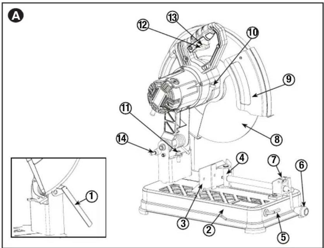
FEATURES (FIGURES A)
- Spark deflector
8.Wheel
-
Base
-
Guard
-
Fence
-
Spindle Lock
-
Vise
-
Depth Stop Bolt and Jam Nut
-
Wrench
-
Trigger Switch
-
Crank
-
Padlock Hole
-
Vise Lever
-
Lock
MAXIMUM CUTTING CAPACITY
NOTE: Capacity shown on chart assumes no wheel wear and optimum fence position.
Workpiece Shape:
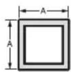
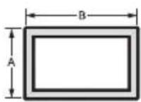
AXB
90^ Cutting Angle
(125mm)
A = 4-7/8 in
(115mm)
A = 4-1/2 in
41/2 in x 5 1/8 in
A = 4 1/2 in x 5 3/8 in
(115mm x 130mm) (115mm x 137mm)
4 in x 7-5/8 in
(102mm x 188mm)
3 in x 7-3/8 in
(76mm x 229mm)
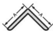
45^ Cutting Angle
A = 4-1/2 in (115mm)
A = 3-13/16 in (98mm)
41/2 in x 3 13/16 in
41/8 in x 3 3/4 in
(105mm x 95mm)
A = 3-13/16 in
3-3/4 in
(95mm)
STANDARD EQUIPMENT
1 14 inch (355mm) Metal Cutting Abrasive Wheel
1 Wheel Wrench
1 Instruction manual
TO CARRY
Fold down unit to position where you can carry the saw. Hook lock to lock arm down.
UNLOCKING
To unlock tool and raise head, depress motor arm slightly and unhook lock out. Motor arm will then pivot upward.
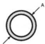
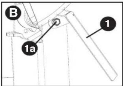
SPARK DEFLECTOR ADJUSTMENT (FIG. B)
To best deflect sparks away from surrounding persons and materials, loosen the screw (1a), adjust the spark deflector (1) and then retighten screw. Do not allow cordset to come into contact with deflector or sparks as damage to cordset may occur.
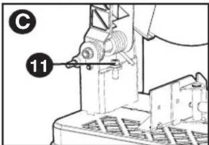
DEPTH STOP (FIG. C)
Depth stop is set at the factory for a new 14 inch (355mm) wheel to prevent wheel from cutting into the supporting surface. To allow more depth of cut, use the wrench (5) to loosen the depth stop bolt (11) and lower bolt to desired height. Then, turn jam nut (11) clockwise until seated firmly on the casting. Securely tighten the depth stop bolt before use.
CAUTION: When changing to a new wheel, readjust depth stop to original position to prevent cutting into supporting surface.
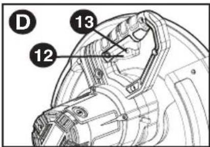
TRIGGER SWITCH (FIG. D)
To start the tool, depress the trigger switch (12). To turn the tool off, release the trigger switch. Keep hands and material
from wheel until it has coasted to a stop. To prevent unauthorized use of tool, install a standard padlock (not included) into the padlock hole (13) located in the trigger.
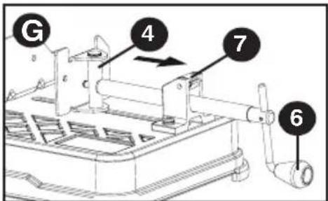
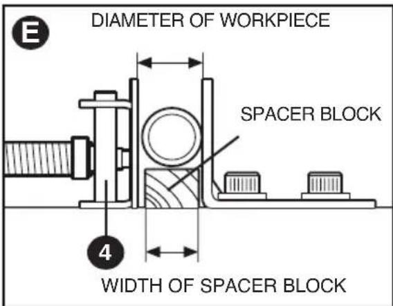
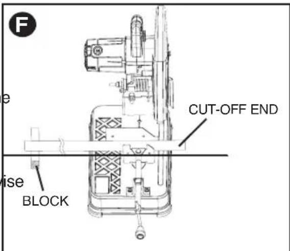
MATERIAL CLAMPING AND SUPPORTING (FIG. E, F)
- Angled material is best clamped and cut with both legs resting against base.
- A spacer block slightly narrower than the workpiece can be used to increase wheel utilization (Fig. E).
- Long workpieces must be supported by a block so it will be level with top of base (Fig. F). The cut off end should be free to fall downward to avoid wheel binding.
The vise (4) has a quick-travel feature. To release the vise when it is clamped tightly, turn the crank counterclockwise one or two times to remove clamping pressure. Lift vise lever (7) up. Pull crank assembly out as far as desired. Vise may be pushed forward into work without cranking. Lower vise lever then tighten vise on work by using crank.
CAUTION: To reduce the risk of injury, turn unit off and disconnect machine from power source before installing and removing accessories, before adjusting or changing set-ups or when making repairs. Be sure the trigger switch is in the OFF position. An
accidental start-up can cause injury.
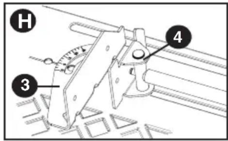
The fence (3) can be adjusted two ways: to change desired cutting angle and to change spacing between the fence and vise.
TO CHANGE THE DESIRED CUTTING ANGLE
Use the wrench (5) provided to loosen (do not remove) the two fence bolts (3a). Align the desired angle indicator line with the slot line (3b) in the base (2). Securely tighten both fence bolts before use. For more accurate square cuts, disconnect the power supply,
loosen the two fence bolts, push arm down until wheel extends into base. Place a square against the wheel and adjust fence against the square. Securely tighten both fence bolts before use. When making a miter cut, the vise (4) may not clamp securely, depending on the thickness of the workpiece and the miter angle. Other aids (such as spring, bar or C-clamps) will be necessary to secure the workpiece to the fence when making these cuts.
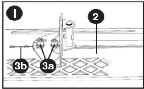
TO CHANGE SPACING BETWEEN THE FENCE AND VISE
Using the wrench provided, loosen and remove the two fence bolts (3a). Adjust the fence (3) to desired locations. Insert both fence bolts in provided locations. Securely tighten both fence bolts before use.
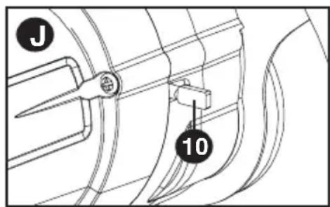
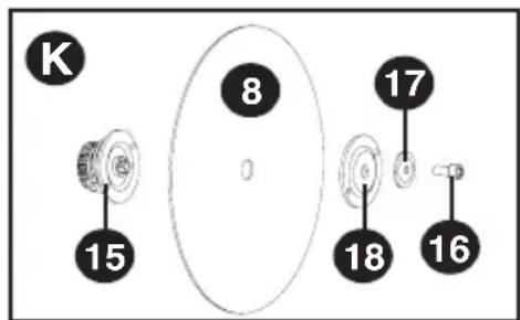
REMOVAL AND INSTALLATION OF WHEELS (FIG. J, K)
CAUTION: Turn off and unplug the tool before making any adjustments or removing or installing attachments or accessories. Be sure the trigger switch is in the OFF position. Do not make any adjustment while the wheel is in motion.
Do not make any adjustment while chop saw is plugged into power supply.
- Push in spindle lock (10) and rotate wheel (8) by hand until wheel lock lever engages slot in inside flange (15) to lock wheel. Loosen the bolt (16) counterclockwise in the center of the abrasive wheel with the included wrench (5). Bolt has right-hand thread.
- Remove the bolt (16), washer (17), outside flange (18) and old wheel (8).
- Make sure flange surfaces are clean and flat. Install the new abrasive wheel by reversing the above steps.
- Do not overtighten bolt.
WARNING: Risk of personal injury. Check the work
surface that the chop saw rests on when replacing with a new abrasive wheel. It is possible that the wheel may contact ANY ITEMS OR STRUCTURE THAT EXTENDS ABOVE work surface (under the base) when the arm is fully lowered.
OPERATION TIPS FOR MORE ACCURATE CUTS
- Allow the wheel to do the cutting. Excessive force will cause the wheel to glaze reducing cutting efficiency and/or to deflect causing inaccurate cuts.
- Properly adjust fence angle.
Make sure material is laying flat across base. - Properly clamp material to avoid movement and vibration.
MAINTENANCE
MOTOR BRUSH INSPECTION AND REPLACEMENT (FIG. L)
WARNING: To reduce the risk of injury, turn unit off and disconnect machine from power source before installing and removing accessories, before adjusting or changing set-ups or when making repairs. Be sure the trigger switch is in the OFF position. An accidental start-up can cause injury.
Brushes should be regularly inspected for wear. To inspect brushes, remove brush cap (19).
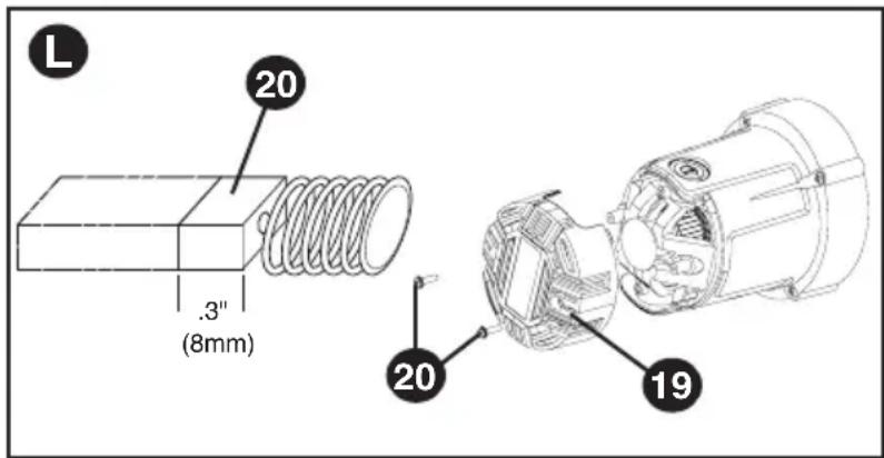
Brushes (20) should slide freely in brush box. If brushes are worn down to .3 inch (8mm) as shown in Figure L they should be replaced. To reinstall, push new brush back into brush box. If replacing existing brush, maintain same orientation as when removed. Replace the brush cap (do not overtighten).
CLEANING
WARNING: Blow dirt and dust out of the main housing with dry air as often as dirt is seen collecting in and around the air vents. Wear ANSI Z87.1 (CAN/CSA Z94.3) approved eye protection when performing this procedure.
CAUTION: When cleaning, use only mild soap and a damp cloth on plastic parts. Many household cleaners contain chemicals which could seriously damage plastic. Also, do not use gasoline, turpentine, lacquer or paint thinner, dry cleaning fluids or similar products which may seriously damage plastic parts. Never let any liquid get inside the tool; never immerse any part of the tool into a liquid.
REPLACEMENT PARTS
Use only identical replacement parts. For a parts list or to order parts, visit our service website at www.portercable.com. You can also order parts from your nearest PORTER-CABLE Factory Service Center or PORTER-CABLE Authorized Warranty Service Center. Or, you can call our Customer Care Center at (888) 848-5175.
SERVICE AND REPAIRS
All quality tools will eventually require servicing and/or replacement of parts. For information about PORTER-CABLE, its factory service centers or authorized warranty service centers, visit our website at www.portercable.com or call our Customer Care Center at (888) 848-5175. All repairs made by our service centers are fully guaranteed against defective material and workmanship. We cannot guarantee repairs made or attempted by others.
You can also write to us for information at PORTER-CABLE, 4825 Highway 45 North, Jackson, Tennessee 38305, (888) 848-5175 - Attention: Product Service. Be sure to include all of the information shown on the nameplate of your tool (model number, type, serial number, etc.).
ACCESSIONS
WARNING: Since accessories, other than those offered by PORTER-CABLE, have not been tested with this product, use of such accessories with this tool could be hazardous. To reduce the risk of injury, only PORTER-CABLE recommended accessories should be used with this product.
A complete line of accessories is available from your PORTER-CABLE Factory Service Center or a PORTER-CABLE Authorized Warranty Service Center. Please visit our Web Site www.portercable.com for a catalog or for the name of your nearest supplier.
NOTE: This equipment has been tested and found to comply with the limits for a Class B digital device, pursuant to Part 15 of the FCC Rules. These limits are designed to provide reasonable protection against harmful interference in a residential installation. This equipment generates, uses and can radiate radio frequency energy and, if not installed and used in accordance with the instructions, may cause harmful interference to radio communications.
However, there is no guarantee that interference will not occur in a particular installation. If this equipment does cause harmful interference to radio or television reception, which can be determined by turning the equipment off and on, the user is encouraged to try to correct
the interference by one or more of the following measures:
- Reorient or relocate the receiving antenna.
- Increase the separation between the equipment and receiver.
- Connect the equipment into an outlet on a circuit different from that to which the receiver is connected.
- Consult the dealer or an experienced radio/TV technician for help.
Changes or modifications to this unit not expressly approved by the party responsible for compliance could void the user's authority to operate the equipment. This Class B digital apparatus complies with Canadian ICES-003.
| Troubleshooting Guide TROUBLE! TOOL WILL NOT START WHAT'S WRONG? WHAT TO DO... 1. Tool not plugged in. 1. Plug in saw. 2. Fuse blown or circuit breaker tripped. 2. Replace fuse or reset circuit breaker. 3. Cord damaged. 3. Have cord replaced by authorized service center. 4. Brushes worn out. 4. Replace brushes. | |
| TROUBLE! TOOL MAKES UNSATISFACTORY CUTS WHAT'S WRONG? WHAT TO DO... 1. Glazed wheel. 1. Dress the wheel or replace with a new one. 2. Workpiece incorrectly placed or clamped. 2. Firmly clamp and support workpiece. | |
| TROUBLE! BLADE DOES NOT COME UP TO SPEED WHAT'S WRONG? WHAT TO DO... 1. Extension cord too light or too long. 1. Replace with adequate size cord. See chart on page 2. 2. Low voltage. 2. Contact your electric company. 3. Low generator voltage. 3. Check generator output voltage. Reduce number of tools powered by the generator. | |
| TROUBLE! TOOL VIBRATES EXCESSIVELY DURING CUT WHAT'S WRONG? WHAT TO DO... 1. Damaged wheel. 1. Replace wheel. 2. Workpiece not clamped properly. 2. Refer to Material Clamping and Supporting page 6. | |
| TROUBLE! DOES NOT MAKE ACCURATE CUTS WHAT'S WRONG? WHAT TO DO... 1. Fence not adjusted correctly. 1. Check and adjust. See Fence Operation on page 7. 2. Wheel is not square to fence. 2. Check and adjust. 3. Excessive force used to make cut. 3. Reduce cutting force, let the wheel do the work. 4. Work piece moving. 4. Clamp workpiece securely. See Material Clamping and Supporting page 6. Make sure material is laying flat against the base. | |
| TROUBLE! MATERIAL MOVES DURING CUT WHAT'S WRONG? WHAT TO DO... 1. Fence slipping or workpiece incorrectly placed or clamped. 1. See Material Clamping and Supporting page 6. 2. Vise too loose 2. Tighten vise clamping. 3. Excessive cutting force. 3. Reduce cutting force. For assistance with your product, visit our website at www.portercable.com for a list of service centers, or call the PORTER-CABLE Customer Care Center at (888) 848-5175. |
THREE YEAR LIMITED WARRANTY
PORTER-CABLE will repair or replace, without charge, any defects due to faulty materials or workmanship for three years from the date of purchase for tools (two years for batteries). This warranty does not cover part failure due to normal wear or tool abuse. For further detail of warranty coverage and warranty repair information, visit www.portercable.com or call (888) 848-5175. This warranty does not apply to accessories or damage caused where repairs have been made or attempted by others. This warranty gives you specific legal rights and you may have other rights which vary in certain states or provinces.
In addition to the warranty, PORTER-CABLE tools are covered by our:
1 YEAR FREE SERVICE: PORTER-CABLE will maintain the tool and replace worn parts caused by normal use, for free, any time during the first year after purchase. 90 DAY MONEY BACK GUARANTEE: If you are not completely satisfied with the performance of your PORTER-CABLE Power Tool for any reason, you can return it within 90 days from the date of purchase with a receipt for a full refund - no questions asked. LATIN AMERICA: This warranty does not apply to products sold in Latin America. For products sold in Latin America, see country specific warranty information contained in the packaging, call the local company or see website for warranty information. To register your tool for warranty service visit our website at www.portercable.com.
WARNING LABEL REPLACEMENT
If your warning labels become illegible or are missing, call (888) 848-5175 for a free replacement.
The following are PORTER-CABLE trademarks for one or more power tools and accessories: a gray and black color scheme; a "four point star" design; and three contrasting/outlined longitudinal stripes. The following are also trademarks for one or more PORTER-CABLE and Delta products: 2 BY 4R , 890^TM , Air America®, AIRBOSS™, Auto-Set®, B.O.S.S.R., Bammer®, Biesemeyer®, Builders Saw®, Charge Air®, Charge Air Pro®, CONTRACTOR SUPERDUTY®, Contractor's Saw®, Delta®, DELTA®, Delta Industrial®, DELTA MACHINERY & DESIGN™, Delta Shopmaster and Design®, Delta X5®, Deltacraft®, DELTAGRAM®, Do It. Feel It.R, DUAL LASERLOC AND DESIGN®, EASY AIR®, EASY AIR TO GO™, ENDURADIAMOND®, Ex-Cell®, Front Bevel Lock®, Get Yours While the Sun Shines®, Grip to Fit®, GRIPVACT™, GTF®, HICKORY WOODWORKING®, Homecraft®, HP FRAMER HIGH PRESSURE®, IMPACT SERIES™, Innovation That Works®, Jet-Lock®, Job Boss®, Kickstand®, LASERLOC®, LONG-LASTING WORK LIFE®, MAX FORCE™, MAX LIFE®, Micro-Set®, Midi-Lathe®, Monsoon®, MONSTER-CARBIDE™, Network®, OLDHAM®, Omnijig®, PC EDGE®, Performance Crew™, Performance Gear®, Pocket Cutter®, Porta-Band®, Porta-Plane®, PORTER-CABLE®, PORTER-CABLE Professional Power Tools®, Powerback®, POZI-STOPTM, Pressure Wave®, PRO 4000®, Proair®, Quicksand and Design®, Quickset II® , QUIET DRIVE TECHNOLOGY™, QUIET DRIVE TECHNOLOGY AND DESIGN™, Quik-Change®, QUIK-TILT®, RAPID-RELEASE™, RAZOR®, Redefining Performance®, Riptide®, Safe Guard II® , Sand Trap and Design®, Sanding Center®, Saw Boss®, Shop Boss®, Sidekick®, Site Boss®, Speed-Bloc®, Speedmatic® , Stair Ease® , Steel Driver Series®, SUPERDUTY® , T4 & DESIGN®, THE AMERICAN WOODSHOP® , THE PROFESSIONAL EDGE® , Thin-Line® , Tiger Saw® , TIGERCLAW® , TIGERCLAW AND DESIGN® , Torq-Buster® , TRU-MATCH® , T-Square® , Twinlaser® , Unifence® , Uniguard® , UNIRIP® , UNISAW® , UNITED STATES SAW® , Veri-Set® , Versa-Feeder® , VIPER® , VT™, VT RAZORTM, Water Driver® , WATER VROOM® , Waveform® , Whisper Series® , X5® , YOUR ACHIEVEMENT. OUR TOOLS ® Trademarks noted with ® are registered in the United States Patent and Trademark Office and may also be registered in other countries. Other trademarks may apply. Les marques de commerce suivies du symbole ® sont enregistrées auprès du United States Patent and Trademark Office et peuvent être enregistrées dans d'autres pays. D'autres marques de commerce peuvent également être applicables. Las MARCAS commerciales con el símbolo ® están registradas en la Oficina de patentes y MARCAS commerciales de Estados Unidos (United States Patent and Trademark Office), y también=Puen estar registadas en otros países. Posiblemente se aplicen除外 MARCAS commerciales registradas.
PORTER CABLE.
4825 Highway 45, North Jackson, TN 38305
(888) 848-5175 / www.portercable.com
LIGNES DIRECTRICES EN MATIÈRE DE SECURITE - DÉFINITIONS
4825 Highway 45, North Jackson, TN 38305
(888) 848-5175 / www.portercable.com
Las siguidentes son MARCAS commerciales PORTER-CABLE que distinguen a una o mas herramientos y accesos: un gráfo de color gris y negro; un Diseño de "estrella de quatre puntas" y tres franjas longitudinales contrastantes/delineadas. Las siguidentes también son MARCAS commerciales para uno o más products de PORTER-CABLE y Delta: 2 BY 4®, 890™, Air America®, AIRBOSS™, Auto-Set®, B.O.S.S®, Bammer®, Biesemeyer®, Builders Saw®, Charge Air®, Charge Air Pro®, CONTRACTOR SUPERDUTY®, Contractor's Saw®, Delta®, DELTA®, Delta Industrial®, DELTA MACHINERY & DESIGN™, Delta Shopmaster and Design®, Delta X5®, Deltacraft®, DELTAGRAM®, Do It. Feel It.®, DUAL LASERLOC AND DESIGN®, EASY AIR®, EASY AIR TO GO™, ENDURADIAMOND®, Ex-Cell®, Front Bevel Lock®, Get Yours While the Sun Shines®, Grip to Fit®, GRIPVAC™, GTF®, HICKORY WOODWORKING®, Homecraft®, HP FRAMER HIGH PRESSURE®, IMPACT SERIES™, Innovation That Works®, Jet-Lock®, Job Boss®, Kickstand®, LASERLOC®, LONG-LASTING WORK LIFE®, MAX FORCE™, MAX LIFE®, Micro-Set®, Midi-Lathe®, Monsoon®, MONSTER-CARBIDE™, Network®, OLDHAM®, Omnijig®, PC EDGE®, Performance Crew™, Performance Gear®, Pocket Cutter®, Porta-Band®, Porta-Plane®, Porter Cable®, PORTER-CABLE Professional Power Tools®, Powerback®, POZI-STOP™, Pressure Wave®, PRO 4000®, Proair®, Quicksand and Design®, Quickset II®, QUIET DRIVE TECHNOLOGY™, QUIET DRIVE TECHNOLOGY AND DESIGN™, Quik-Change®, QUIK-TILT®, RAPID-RELEASE™, RAZOR®, Redefining Performance®, Riptide®, Safe Guard II® Sand Trap and Design®, Sanding Center®, Saw Boss®, Shop Boss®, Sidekick®, Site Boss®, Speed-Bloc®, Speedmatic®, Stair Ease®, Steel Driver Series®, SUPERDUTY®, T4 & DESIGN®, THE AMERICAN WOODSHOP® THE PROFESSIONAL EDGE® Thin-Line® Tiger Saw® TIGERCLAW® TIGERCLAW AND DESIGN® Torq-Buster® TRU-MATCH® T-Square® Twinlaser® Unifence® Uniguard® UNIRIP® UNISAW® UNITED STATES SAW® Veri-Set® Versa-Feeder® VIPER® VT™ VT RAZOR™ Water Driver® WATER VROOM® Waveform® Whisper Series® X5® YOUR ACHIEVEMENT. OUR TOOLS®
4825 Highway 45, North Jackson, TN 38305
(888) 848-5175 / www.portercable.com