
Bluehelix Tech S 45 H - Central heating boiler FERROLI - Free user manual and instructions
Find the device manual for free Bluehelix Tech S 45 H FERROLI in PDF.
| Product type | Condensing central heating boiler, sealed chamber, premix |
| Brand | Ferroli |
| Model | Bluehelix Tech S 45 H |
| Weight | 35 kg |
| Power supply | 230 V / 50 Hz |
| Electrical power consumption | 172 W |
| Gas type | Natural gas (G20) or LPG (G31) |
| Gas supply pressure | G20: 20 mbar, G31: 37 mbar |
| Maximum heating thermal input | 43.0 kW |
| Maximum heating thermal output (80/60°C) | 41.8 kW |
| Minimum heating thermal output (80/60°C) | 7.3 kW |
| Efficiency at nominal power (80/60°C) | 93% |
| Maximum heating temperature | 95 °C |
| Maximum operating pressure heating | 4.5 bar |
| Minimum operating pressure heating | 0.8 bar |
| Heating circuit water capacity | 4.88 liters |
| Protection rating | IP X5D |
| Main functions | Central heating and domestic hot water production (with optional external tank), Summer/Winter modes, Eco/Comfort modes, weather-compensated temperature with outdoor sensor, frost protection |
| Maintenance | Annual inspection and cleaning by a qualified professional; check of heat exchanger, burner, electrodes, etc. |
| Safety | Safety valve, overheat protection, flame safety, ventilation, flame failure detection |
| Spare parts and repairability | Use only genuine spare parts; any repair must be carried out by a qualified technician |
| Appliance type (flue ducts) | C13-C23-C33-C43-C53-C63-C83-B23-B33 |
Frequently Asked Questions - Bluehelix Tech S 45 H FERROLI
User questions about Bluehelix Tech S 45 H FERROLI
0 question about this device. Answer the ones you know or ask your own.
Ask a new question about this device
Download the instructions for your Central heating boiler in PDF format for free! Find your manual Bluehelix Tech S 45 H - FERROLI and take your electronic device back in hand. On this page are published all the documents necessary for the use of your device. Bluehelix Tech S 45 H by FERROLI.
USER MANUAL Bluehelix Tech S 45 H FERROLI
BLUEHELIX TECH S 45H


CE EAC
OFFSET = 20OFFSET = 40


fig. 21

fig. 22
fig. 24 - Apertura pannello frontale

OFFSET = 20OFFSET = 40


fig. 21

fig. 22
fig. 24 - Apertura del panel frontal

OFFSET = 20OFFSET = 40


şek. 21

şek. 22
- Carefully read and follow the instructions contained in this instruction booklet.
• After boiler installation, inform the user regarding its operation and give him this manual, which is an integral and essential part of the product and must be kept with care for future reference.
• Installation and maintenance must be carried out by professionally qualified personnel, in compliance with the current regulations and according to the manufacturer's instructions. Do not carry out any operation on the sealed control parts. - Incorrect installation or inadequate maintenance can result in damage or injury. The Manufacturer declines any liability for damage due to errors in installation and use, or failure to follow the instructions.
- Before carrying out any cleaning or maintenance operation, disconnect the unit from the electrical power supply using the switch and/or the special cut-off devices.
- In case of a fault and/or poor operation, deactivate the unit and do not try to repair it or directly intervene. Contact professionally qualified personnel. Any repair/replacement of the products must only be carried out by qualified personnel using original replacement parts. Failure to comply with the above could affect the safety of the unit.
- This unit must only be used for its intended purpose. Any other use is deemed improper and therefore hazardous.
- The packing materials are potentially hazardous and must not be left within the reach of children.
- The unit must not be used by people (including children) with limited physical, sensory or mental abilities or without experience and knowledge of it, unless instructed or supervised in its use by someone responsible for their safety.
- The unit and its accessories must be appropriately disposed of, in compliance with the current regulations.
- The images given in this manual are a simplified representation of the product. In this representation there may be slight and insignificant differences with respect to the product supplied.
2. OPERATING INSTRUCTIONS
2.1 Introduction
Dear Customer,
BLUEHELIX TECH S 45H is a high-efficiency, low emissions premix condensing heat generator with heat exchanger in steel and incorporated DHW production, running on natural gas or LPG and equipped with a microprocessor control system.
The sealed chamber unit is suitable for indoor installation or outdoors in a partially protected place (according to EN 297/A6) with temperatures to -5°C.

The boiler is arranged for connection to an external storage tank for hot water (optional). In this manual all the functions relevant to domestic hot water production are only active with the optional hot water tank connected as indicated in sec. 3.3
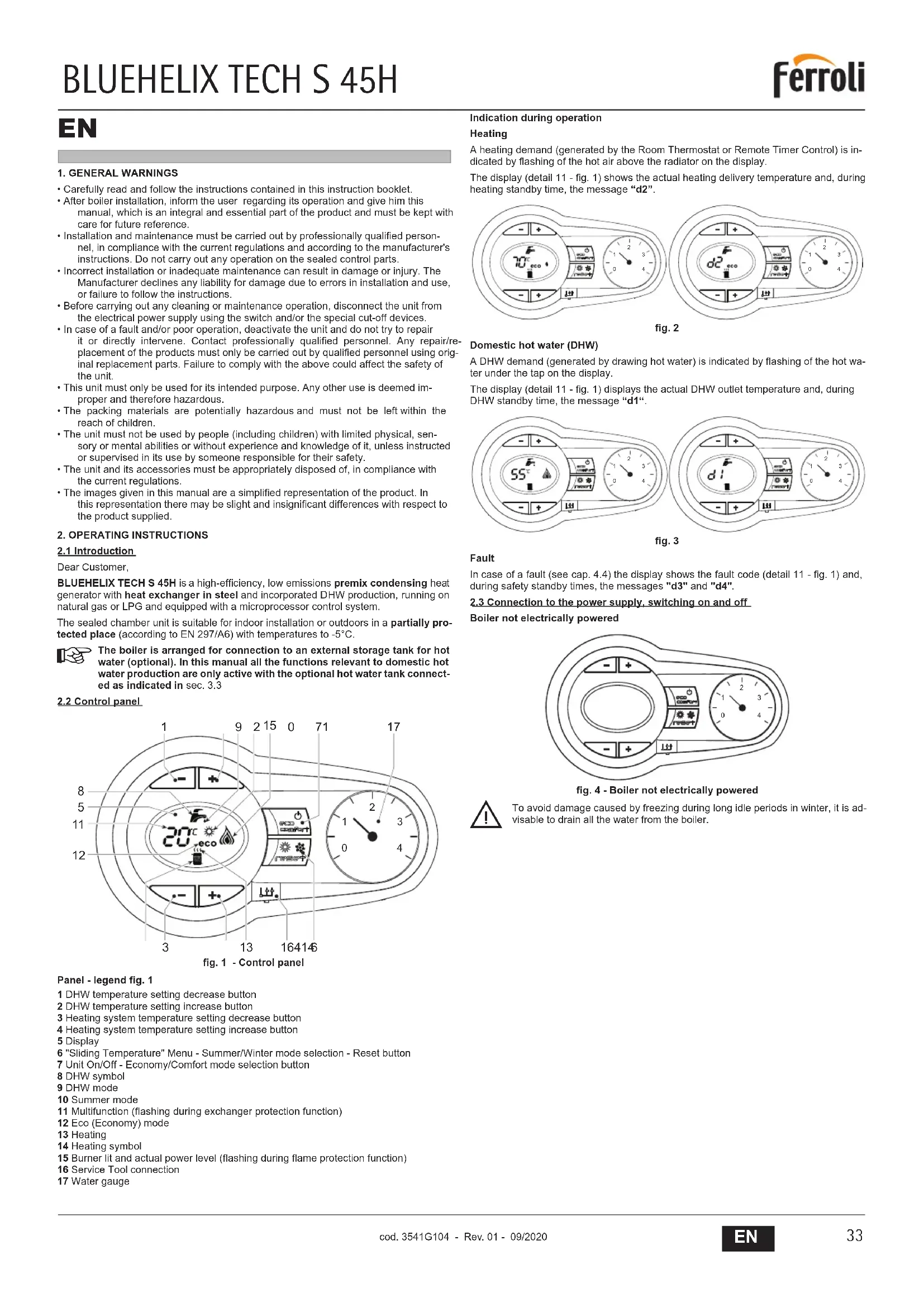
2.2 Control panel
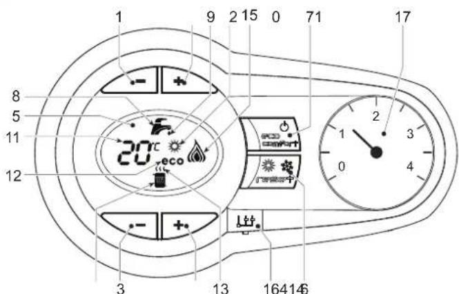
fig. 1 - Control panel
Panel - legend fig. 1
1 DHW temperature setting decrease button
2 DHW temperature setting increase button
3 Heating system temperature setting decrease button
4 Heating system temperature setting increase button
5 Display
6 "Sliding Temperature" Menu - Summer/Winter mode selection - Reset button
7 Unit On/Off - Economy/Comfort mode selection button
8 DHW symbol
9 DHW mode
10 Summer mode
11 Multifunction (flashing during exchanger protection function)
12 Eco (Economy) mode
13 Heating
14 Heating symbol
15 Burner lit and actual power level (flashing during flame protection function)
16 Service Tool connection
17 Water gauge
Indication during operation
Heating
A heating demand (generated by the Room Thermostat or Remote Timer Control) is indicated by flashing of the hot air above the radiator on the display.
The display (detail 11 - fig. 1) shows the actual heating delivery temperature and, during heating standby time, the message "d2".

fig. 2
Domestic hot water (DHW)
A DHW demand (generated by drawing hot water) is indicated by flashing of the hot water under the tap on the display.
The display (detail 11 - fig. 1) displays the actual DHW outlet temperature and, during DHW standby time, the message "d1".
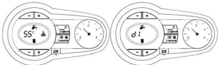
fig. 3
Fault
In case of a fault (see cap. 4.4) the display shows the fault code (detail 11 - fig. 1) and, during safely standby times, the messages "d3" and "d4".
2.3 Connection to the power supply, switching on and off
Boiler not electrically powered

fig. 4 - Boiler not electrically powered

To avoid damage caused by freezing during long idle periods in winter, it is advisable to drain all the water from the boiler.
Boiler electrically powered
Switch on the power to the boiler.

fig. 5 - Switching on / Software version

fig. 6 - Venting cycle
- During the first 5 seconds the display also shows the card software version
- For the following 300 seconds the display shows FH which identifies the heating system air venting cycle.
- Open the gas cock ahead of the boiler
- When the message FH disappears, the boiler is ready to operate automatically whenever domestic hot water is drawn or in case of a room thermostat demand
Switching the boiler off and on
Press the on/off button (detail 7 - fig. 1) for 5 seconds.
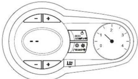
fig. 7 - Switching the boiler off
When the boiler is switched off, the electronic board is still powered. Domestic hot water and heating are disabled The antifreeze system remains activated. To switch the boiler on, press the on/off button (detail 7 - fig. 1) again for 5 seconds.

fig. 8
The boiler will be immediately ready to operate whenever domestic hot water is drawn or in case of a room thermostat demand.

The antifreeze system does not work when the power and/or gas to the unit are turned off. To avoid damage caused by freezing during long shutdowns in winter, it is advisable to drain all water from the boiler, the DHW circuit and the heating system water; or drain just the DHW circuit and add a suitable antifreeze to the heating system, as prescribed in sec. 3.3.
2.4 Adjustments
Summer/Winter Switchover
Press the summer/winter button (detail 6 - fig. 1) for 2 seconds.
The display activates the Summer symbol (detail 10 - fig. 1): the boiler will only deliver domestic hot water. The antifreeze system remains activated.
To deactivate the Summer mode, press the summer/winter button (detail 6 - fig. 1) again for 2 seconds.
Heating temperature adjustment
Use the heating buttons (details 3 and 4 - fig. 1) to adjust the temperature from a min. of 20°C to a max. of 80°C .

fig. 9
DHW temperature adjustment
Use the DHW buttons (details 1 and 2 - fig. 1) to adjust the temperature from a minimum of 10° C to a maximum of 65° C.

fig. 10
Room temperature adjustment (with optional room thermostat)
Using the room thermostat, set the temperature required in the rooms. If the room thermostat is not installed, the boiler will keep the system at the set system delivery setpoint temperature.
Room temperature adjustment (with optional remote timer control)
Using the remote timer control, set the required temperature in the rooms. The boiler will adjust the system water according to the required room temperature. For operation with remote timer control, please refer to the relevant instruction manual.
Hot water tank exclusion (economy)
Hot water tank temperature maintaining/heating can be excluded by the user. If excluded, domestic hot water will not be delivered.
The hot water tank can be deactivated by the user (ECO mode) by pressing the ECO/COMFORT button (detail 7 - fig. 1). In ECO mode the display activates the ECO symbol (detail 12 - fig. 1). To activate COMFORT mode, press the ECO/COMFORT button (detail 7 - fig. 1) again.
Sliding Temperature
When the optional external probe is installed, the boiler adjustment system works with "Sliding Temperature". In this mode, the temperature of the heating system is controlled according to the outside weather conditions, to ensure high comfort and energy saving throughout the year. In particular, the system delivery temperature is decreased as the outside temperature increases, according to a specific "compensation curve".
With Sliding Temperature adjustment, the temperature set with the heating buttons (detail 3 - fig. 1) becomes the maximum system delivery temperature. It is advisable to set a maximum value to allow system adjustment throughout its useful operating range.
The boiler must be adjusted at the time of installation by qualified personnel. Possible adjustments can in any case be made by the user to improve comfort.
Compensation curve and curve offset
Press the reset button (detail 6 - fig. 1) for 5 seconds to access the "Sliding temperature" menu; the display shows "CU" flashing.
Use the DHW buttons (detail 1 - fig. 1) to adjust the curve from 1 to 10 according to the characteristic. By setting the curve to 0, sliding temperature adjustment is disabled.
Press the heating buttons (detail 3 - fig. 1) to access parallel curve offset; the display shows "OF" flashing. Use the DHW buttons (detail 1 - fig. 1) to adjust the parallel curve offset according to the characteristic (fig. 11).
Press the reset button (detail 6 - fig. 1) again for 5 seconds to exit the "Sliding Temperature" menu.
If the room temperature is lower than the required value, it is advisable to set a higher order curve and vice versa. Proceed by increasing or decreasing in steps of one and check the result in the room.
OFFSET = 20OFFSET = 40


fig. 11 - Example of compensation parallel curve offset
Adjustments from Remote Timer Control

If the Remote Timer Control (optional) is connected to the boiler, the above adjustments are managed according to that given in table 1.
Table. 1
| Heating temperature setting | Adjustment can be made from the Remote Timer Control menu and the boiler control panel. |
| DHW temperature adjustment | Adjustment can be made from the Remote Timer Control menu and the boiler control panel. |
| Summer/Winter Switchover | Summer mode has priority over a possible Remote Timer Control heating demand. |
| Eco/Comfort selection | On disabling DHW from the Remote Timer Control menu, the boiler selects the Economy mode. In this condition, the eco/comfort button (detail 7 - fig. 1) on the boiler panel is disabled. |
| On enabling DHW from the Remote Timer Control menu, the boiler selects the Comfort mode. In this condition it is possible select one of the two modes with the eco/comfort button (detail 7 - fig. 1) on the boiler panel. | |
| Sliding Temperature | Both the Remote Timer Control and the boiler card manage Sliding Temperature adjustment: the boiler card Sliding Temperature has priority. |
System water pressure adjustment
The filling pressure read on the boiler water gauge with the system cold must be approx 1.0 bar. If the system pressure falls to values below minimum, the boiler stops and fault F37 is displayed.
Once the system pressure is restored, the boiler will activate the 300-second air venting cycle indicated on the display by FH.
3. INSTALLATION
3.1 General Instructions
BOILER INSTALLATION MUST ONLY BE PERFORMED BY QUALIFIED PERSONNEL, IN ACCORDANCE WITH ALL THE INSTRUCTIONS GIVEN IN THIS TECHNICAL MANUAL, THE PROVISIONS OF CURRENT LAW, THE PRESCRIPTIONS OF NATIONAL AND LOCAL STANDARDS AND THE RULES OF PROPER WORKMANSHIP.
3.2 Place of installation
The combustion circuit is sealed with respect to the place of installation room, therefore the unit can be installed in any room. However, the place of installation must be adequately ventilated to prevent the creation of dangerous conditions in case of even small gas leaks. This safety regulation is laid down by EEC Directive no. 2009/142 for all gas units, including those with sealed chamber.
The unit is designed to operate in a partially protected place according to EN 297/A6, with minimum temperature of -5°C . The boiler must be installed in a sheltered place, e.g. under the slope of a roof, inside a balcony or in a protected recess.
The place of installation must be free of flammable materials, objects and dusts or corrosive gases.
The boiler is arranged for wall mounting and comes as standard with a hooking bracket. Wall fixing must ensure stable and effective support for the generator.

If the unit is enclosed in a cabinet or mounted alongside, there must be sufficient space for removing the casing and for normal maintenance activities
3.3 Plumbing connections
Important

The safety valve outlet must be connected to a funnel or collection pipe to prevent water spurting onto the floor in case of overpressure in the heating circuit. Otherwise, if the discharge valve cuts in and floods the room, the boiler manufacturer cannot be held liable.

Before installation, flush all the pipes of the system thoroughly to remove any residuals or impurities that could affect proper operation of the unit.
In case of replacement of generators in existing installations, the system must be completely emptied and cleaned of any sludge and pollutants. For that purpose only use suitable guaranteed products for heating systems (see next section), that do not harm metals, plastics or rubber. The manufacturer declines any liability for damage caused to the generator by failure to properly clean the system.
Carry out the relevant connections according to the diagram in fig. 12 and the symbols given on the unit.

fig. 12 - Plumbing connections
1 = System delivery - ∅ 3/4"
3 = Gas inlet - ∅ 1/2"
5 = System return - ∅ 3/4"
Antifreeze system, antifreeze fluids, additives and inhibitors
When necessary, antifreeze fluids, additives and inhibitors can be used only if the manufacturer of such fluids or additives guarantees that they are suitable and do not cause damage to the exchanger or other components and/or materials of the boiler and system. Do not use generic antifreeze fluids, additives or inhibitors that are not specific for use in heating systems and compatible with the materials of the boiler and system.
Water system characteristics
In the presence of water harder than 25°Fr (1°F = 10ppmCaCO3) , use suitably treated water in order to avoid possible scaling in the boiler.
Connection to a storage tank for domestic hot water production
The unit's electronic board is arranged for managing an external storage tank for domestic hot water production. Carry out the plumbing connections according to the diagram of fig. 13. Carry out the electrical connections as shown on the wiring diagram in fig. 29. At the next lighting, the boiler control system detects the hot water tank probe and automatically configures the DHW function, activating the display and relevant controls.
![graph TD A["Refrigerator 10"] --> B["Refrigerator 11"] B --> C["Condenser 95"] C --> D["Refrigerator 8"] D --> E["Refrigerator 9"] E --> F["Refrigerator 8"] style A fill:#f9f,stroke:#333 style B fill:#f9f,stroke:#333 style C fill:#ccf,stroke:#333 style D fill:#ccf,stroke:#333 style E fill:#ccf,strok…](/content/2026/03/519996/images/c56dd4b1c91a9c8a046e490e42ba9b290aaad932d18f71ede7bf4e575e5a9513.jpg)
fig. 13 - Diagram of connection to external hot water tank
8 Domestic hot water outlet
9 Cold water inlet
10 System delivery - ∅ 3/4"
11 System return - ∅ 3/4"
95 Divverter valve
3.4 Gas connection

Before making the connection, ensure that the unit is arranged for operation with the type of fuel available.
The gas must be connected to the relevant connection (see fig. 12) in conformity with the current standards, using a rigid metal pipe or a continuous surface flexible s/steel tube and installing a gas cock between the system and boiler. Make sure all the gas connections are tight.
3.5 Electrical connections

The unit must be connected to an efficient earthing system in accordance with current safety standards. Have the efficiency and suitability of the earthing system checked by professionally qualified personnel; the Manufacturer declines any liability for damage caused by failure to earth the system.
The boiler is prewired and provided with a "Y" type cable (without plug) for connection to the electric line. The connections to the grid must be made with a permanent connection and equipped with a bipolar switch whose contacts have a minimum opening of at least 3 mm, interposing fuses of max. 3A between the boiler and the line. Make sure to respect the polarities (LINE: brown wire / NEUTRAL: blue wire / EARTH: yellow-green wire) in the connections to the electric line.

The unit's power cable must not be replaced by the user. If the cable gets damaged, switch off the unit and have it replaced only by professionally qualified personnel. In case of replacement, use exclusively "HAR H05 VV-F" 3x0.75 mm2 cable with maximum ext. diameter of 8 mm.
Room thermostat (optional)

IMPORTANT: THE ROOM THERMOSTAT MUST HAVE VOLTAGE-FREE CONTACTS. CONNECTING 230V TO THE ROOM THERMOSTAT TERMINALS WILL PERMANENTLY DAMAGE THE PCB.
When connecting a time control or timer, do not take the power supply for such devices from their cutoff contacts. Their power supply must be taken with a direct connection from the mains or with batteries, depending on the type of device.
Accessing the electrical terminal block
After removing the front panel ( 'Opening the front panel' on page 38 ) it is possible to access the electrical connections terminal block (fig. 14). The layout of the terminals for the various connections is given in the wiring diagram in fig. 29.

fig. 14 - Accessing the terminal block
3.6 Fume ducts
Important
The unit is "type C" with sealed chamber and forced draught; the air inlet and fume outlet must be connected to one of the following extraction/suction systems. Before installation, check and carefully observe the above prescriptions. Also, comply with the provisions concerning the positioning of wall and/or roof terminals and the minimum distances from windows, walls, vents, etc.
Connection with coaxial pipes
![graph TD A["C1x"] --> B["Drain Unit"] C["C3x"] --> D["Drain Unit"] E["C3x"] --> F["Drain Unit"] G["C3x"] --> H["Drain Unit"] I["C1x"] --> J["Drain Unit"] K["C1x"] --> L["Drain Unit"]](/content/2026/03/519996/images/e9b490afd52ae65236381f799705de470688266e58e6c6a5bf6afe0c4f1784ec.jpg)
fig. 15 - Examples of connection with coaxial pipes ( = Air / = Pipes)
Table. 2 - Typology
| Type Description | |
| C1X | Wall horizontal exhaust and inlet |
| C3X | Roof vertical exhaust and inlet |
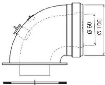
For coaxial connection, fit the unit with one of the following starting accessories. For the wall hole dimensions, refer to the figure on the cover. Any horizontal sections of the fume exhaust must be kept sloping slightly towards the boiler, to prevent possible condensate from flowing back towards the outside and causing dripping.

041002X0

041006X0
041001X0
fig. 16 - Starting accessory for coaxial ducts
Table. 3 - Max. length coaxial ducts
| Coaxial 60/100 Coaxia | 80/125 | |
| Max. permissible length (horizontal) | 5 m | 15 m |
| Max. permissible length (vertical) | 6 m | |
| Reduction factor 90° bend | 1 m 0.5 m | |
| Reduction factor 45° bend | 0.5 m 0.25 m |
Connection with separate pipes


fig. 17 - Examples of connection with separate pipes ( = Air / = Fumes)
Table. 4 - Typology
| Type | Description |
| C1X | Wall horizontal exhaust and intake. The inlet/outlet terminals must be concentric or close enough to be undergo similar wind conditions (within 50 cm) |
| C3X | Roof vertical exhaust and intake. Inlet/outlet terminals like for C12 |
| C5X | Wall or roof exhaust and intake separate or in any case in areas with different pressures. The exhaust and intake must not be positioned on opposite walls. |
| C6X | Intake and exhaust with separately certified pipes (EN 1856/1) |
| B2X | Intake from installation room and wall or roof exhaustIMPORTANT - THE ROOM MUST BE PROVIDED WITH APPROPRIATE VENTILATION |
For the connection of separate ducts, fit the unit with the following starting accessory:

fig. 18 - Starting accessory for separate ducts
Before proceeding with installation make sure the maximum permissible length has not been exceeded, by means of a simple calculation:
- Completely establish the layout of the system of split flues, including accessories and outlet terminals.
- Consult table 6 and identify the losses in m eq (equivalent metres) of every component, according to the installation position.
- Check that the sum total of losses is less than or equal to the maximum permissible length in table 5.
Table. 5 - Max. length separate ducts
| Max. permissible length | 40 mec |
Table. 6 - Accessories
| Losses in meq | ||||||
| Air Inlet | Fume exhaust | |||||
| Vertical Horizontal | ||||||
| ∅ 80 | PIPE | 1 m M/F 1KWMA83W 1.0 1.6 2.0 | ||||
| BEND | 45° M/F 1KWMA65W 1.2 1.8 | |||||
| 90° M/F 1KWMA01W 1.5 2.0 | ||||||
| PIPE SECTION | with test point | 1KWMA70W | 0.3 | 0.3 | ||
| TERMINAL | air, wall | 1KWMA85A | 2.0 | - | ||
| fumes, wall with antiwind | 1KWMA86A | - | 5.0 | |||
| FLUE | Split air/fumes 80/80 | 010027X0 | - | 12.0 | ||
| Fume outlet only ∅80 010026X0 + 1KWMA86U | - | 4.0 | ||||
| ∅ 60 | PIPE | 1 m M/F 1KWMA89W | 6.0 | |||
| BEND | 90° M/F 1KWMA88W | 4.5 | ||||
| REDUCTION | 80/60 | 041050X0 | 5.0 | |||
| TERMINAL | fumes, wall with antiwind | 1KWMA90A | 7.0 | |||
| ATTENTION: CONSIDER THE HIGH PRESSURE LOSSES OF ∅60 ACCESSORIES;USE THEM ONLY IF NECESSARY AND AT THE LAST FUME EXHAUST SECTION. | ||||||
Connection to collective flues

fig. 19 - Examples of connection to flues ( = Air / = F→s)
Table. 7 - Typology
| Type | Description |
| C2X | Intake and exhaust in common flue (intake and exhaust in same flue) |
| C4X | Intake and exhaust in common and separate flues, but undergoing similar wind conditions |
| C8X | Exhaust in single or common flue and wall intake |
| B3X | Intake from installation room by means of concentric duct (that encloses the exhaust) and exhaust in common flue with natural draughtIMPORTANT - THE ROOM MUST BE PROVIDED WITH APPROPRIATE VENTILATION |
If the boiler is to be connected BLUEHELIX TECH S 45H to a collective flue or a single flue with natural draught, the flue or chimney must be expressly designed by professionally qualified technical personnel in conformity with the current regulations and be suitable for sealed chamber units equipped with fan.
3.7 Condensate drain connection
The boiler has an internal trap for draining condensate. Fit the inspection union A and the hose B, pressing it in. Fill the air-trap with approximately 0.5 l. of water and connect the hose to the disposal system
ATTENTION: The unit must never be operated with the trap empty!
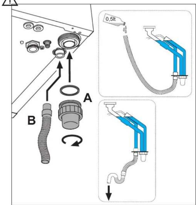
fig. 20 - Condensate outlet connection
4. SERVICE AND MAINTENANCE
4.1 Adjustments
Gas conversion
The unit can operate on Natural Gas or LPG and is factory-set for use with one of these two gases, as clearly shown on the packing and on the data plate. Whenever a different gas to that for which the unit is arranged has to be used, a conversion kit will be required, proceeding as follows:
- Remove the front panel (see *** 'Opening the front panel' on page 38 ***)
- Undo the screw and rotate the control panel (see fig. 21).
- Unscrew ring C and remove gas pipe A from the gas valve (see fig. 22).
- Replace nozzle B inserted in the gas pipe with that contained in the conversion kit, interposing seal D (see fig. 22).
- Refit gas pipe A and check the tightness of the connection.
- Apply the label, contained in the conversion kit, near the data plate.
- Refit the front panel.
- Modify the parameter for the type of gas:
- put the boiler in standby mode
- press the DHW buttons (details 1 and 2 - fig. 1) for 10 seconds: the display shows "b01" flashing.
- press the DHW buttons (details 1 or 2 - fig. 1) to set parameter 00 (for operation with natural gas) or 01 (for operation with LPG).
- press the heating + button (detail 4 - fig. 1) until "b04" flashes on the display.
- press the DHW buttons (details 1 or 2 - fig. 1) to set parameter 200 (for operation with natural gas) or 190 (for operation with LPG).
- press the heating + button (detail 4 - fig. 1) until "b05" flashes on the display
- press the DHW buttons (details 1 or 2 - fig. 1) to set parameter 200 (for operation with natural gas) or 190 (for operation with LPG).
- press the DHW buttons (details 1 and 2 - fig. 1) for 10 seconds.
-
the boiler will return to standby mode
-
Using a combustion analyser connected to the boiler fume outlet, check that the CO2 content in the fumes, with the boiler operating at max. and min. output, matches that given in the technical data table for the corresponding type of gas.

fig. 21

fig. 22
TEST mode activation
Press the heating buttons (details 3 and 4 - fig. 1) together for 5 seconds to activate the TEST mode. The boiler lights at the maximum heating power set as described in the following section.
The heating and DHW symbols (fig. 23) flash on the display; the heating power will appear alongside.

fig. 23 - TEST mode (heating power = 100%)
Press the heating buttons (details 3 and 4 - fig. 1) to increase or decrease the power (Min.=0%, Max.=100%).
By pressing the DHW “-” button (detail 1 - fig. 1), boiler output is immediately adjusted to min. (0%). By pressing the DHW “+” button (detail 2 - fig. 1), boiler output is immediately adjusted to max. (100%).
If the TEST mode is activated and enough hot water is drawn to activate the DHW mode, the boiler remains in TEST mode but the 3-way valve goes to DHW.
To deactivate the TEST mode, press the heating buttons (details 3 and 4 - fig. 1) together for 5 seconds.
The TEST mode is automatically deactivated in any case after 15 minutes or on stopping of hot water drawing (if enough hot water has been drawn to activate the DHW mode).
Heating power adjustment
To adjust the heating power, switch the boiler to TEST mode (see sec. 4.1). Press the heating buttons (details 3 and 4 - fig. 1) to increase or decrease the power (min. = 00 - max. = 100). Press the RESET button within 5 seconds and the max. power will remain that just set. Exit TEST mode (see sec. 4.1).
4.2 Startup
Before lighting the boiler
- Check the seal of the gas system.
- Check correct prefilling of the expansion tank.
- Fill the water system and make sure all air contained in the boiler and the system has been vented.
- Make sure there are no water leaks in the system, DHW circuits, connections or boiler.
- Check correct connection of the electrical system and efficiency of the earthing system.
- Make sure the gas pressure for heating is that required.
- Make sure there are no flammable liquids or materials in the immediate vicinity of the boiler
Checks during operation
- Switch the unit on.
- Check the tightness of the fuel circuit and water systems.
- Check the efficiency of the flue and air/fume ducts while the boiler is working.
- Check the correct tightness and efficiency of the condensate removal system and trap.
- Make sure the water is circulating properly between the boiler and systems.
- Make sure the gas valve modulates correctly in heating and domestic hot water production.
- Check proper lighting of the boiler by turning it on and off several times with the room thermostat or remote control.
- Make sure the fuel consumption indicated on the meter matches that given in the technical data table on cap. 5.
- Make sure that with no heating demand the burner correctly lights on opening a hot water tap. Check that the heating circulating pump stops on opening a hot water tap during heating operation and there is a regular production of hot water.
- Check correct programming of the parameters and carry out any required customisation (compensation curve, power, temperatures, etc.).
4.3 Maintenance
Opening the front panel
To open the boiler casing:
- Partially undo the screws A (see fig. 24).
- Pull the panel B outwards and release it from the upper fastenings.
Before carrying out any operation inside the boiler, disconnect the power and close the gas cock upstream

fig. 24 - Front panel opening

On this unit, the casing also acts as a sealed chamber. After any operation involving opening the boiler, carefully check the correct refitting of the front panel and its seal.
BLUEHELIX TECH S 45H
Proceed in reverse order to refit the front panel. Make sure it is correctly hooked to the upper fastenings and is correctly positioned at the sides. When tightened, the head of screw "A" must not be below the lower fold (see fig. 25).

fig. 25 - Correct position of front panel
Periodical check
To ensure proper operation of the unit over time, have qualified personnel carry out a yearly inspection, providing for the following checks:
- The control and safety devices (gas valve, flow meter, thermostats, etc.) must function correctly
• The fume exhaust circuit must be perfectly efficient
• The sealed chamber must be tight - The air-fume end piece and ducts must be free of obstructions and leaks
• The burner and exchanger must be clean and free of deposits For possible cleaning do not use chemical products or wire brushes
• The electrode must be properly positioned and free of scale
• The gas and water systems must be tight. - The water pressure in the cold water system must be about 1 bar; otherwise, bring it to that value
• The circulating pump must not be blocked.
• The expansion tank must be filled.
• The gas flow and pressure must correspond to that given in the respective tables - The condensate evacuation system must be efficient with no leakage or obstructions
• The trap must be full of water.
4.4 Troubleshooting
Diagnostics
In case of operation faults or problems, the display flashes and the fault identification code appears.
There are faults that cause permanent shutdown (marked with the letter "A"): to restore operation just press the reset button (detail 6 - fig. 1) for 1 second or RESET on the optional remote timer control if installed; if the boiler fails to start, it is necessary to firstly eliminate the fault.
Faults marked with the letter "F" cause temporary shutdowns that are automatically reset as soon as the value returns within the boiler's normal working range.
Table of faults
Table. 8 - List of faults
| Fault code | Fault Possible cause Cure | ||
| A01 | No burner ignition | No gas | Check the regular gas flow to the boiler and that the air has been eliminated from the pipes |
| Ignition/detection electrode fault | Check the wiring of the electrode and that it is correctly positioned and free of any deposits | ||
| Faulty gas valve | Check the gas valve and replace it if necessary | ||
| Insufficient gas supply pressure Check | the gas supply pressure | ||
| Trap blocked | Check the trap and clean it if necessary | ||
| A02 | Flame present signal with burner off | Electrode fault Check the ionisation electrode wiring | |
| Card fault Check the card | |||
| A03 | Overtemperature protection intervention | Heating sensor damaged | Check the correct positioning and operation of the heating sensor |
| No water circulation in the system Check the circulating pump | |||
| Air in the system Vent the system | |||
| A04 | Fume extraction duct safety device intervention | Fault F07 generated 3 times in the last 24 hours | See fault F07 |
| A05 | Fan protection activated | Fault F15 generated for 1 hour (consecutive) | See fault F15 |
| Fault code | Fault | Possible cause Cure | |
| A06 | No flame after ignition stage (6 times in 4 minutes) | Ionisation electrode fault Check the position of the ionisation electrode and replace it if necessary | |
| Flame unstable Check the bumer | |||
| Gas valve Offset fault | Check the Offset adjustment at minimum power | ||
| air/fume ducts obstructed | Remove the obstruction from the fuse, fume extraction ducts and air inlet and terminals | ||
| Trap blocked | Check the trap and clean it if necessary | ||
| F07 | High fume temperature | The fume probe detects an excessive temperature | Check the exchanger |
| F10 | Delivery sensor 1 fault | Sensor damaged | Check the wiring or replace the sensor |
| Wiring shorted | |||
| Wiring disconnected | |||
| F11 | Return sensor fault | Sensor damaged | Check the wiring or replace the sensor |
| Wiring shorted | |||
| Wiring disconnected | |||
| F12 | DHW sensor fault | Sensor damaged | Check the wiring or replace the sensor |
| Wiring shorted | |||
| Wiring disconnected | |||
| F13 | Fume probe fault | Probe damaged | Check the wiring or replace the fume probe |
| Wiring shorted | |||
| Wiring disconnected | |||
| F14 | Delivery sensor 2 fault | Sensor damaged | Check the wiring or replace the sensor |
| Wiring shorted | |||
| Wiring disconnected | |||
| F15 | Fan fault | No 230V power supply | Check the 3-pin connector wiring |
| Tachometric signal interrupted | Check the 5-pin connector wiring | ||
| Fan damaged | Check the fan | ||
| F34 | Supply voltage under 170V | Electric mains trouble | Check the electrical system |
| F35 | Faulty mains frequency | Electric mains trouble | Check the electrical system |
| F37 | Incorrect system water pressure | Pressure too low | Fill the system |
| Water pressure switch damaged or not connected | Check the sensor | ||
| F39 | External probe fault | Probe damaged or wiring shorted | Check the wiring or replace the sensor |
| Probe disconnected after activating the sliding temperature | Reconnect the external probe or disable the sliding temperature | ||
| A41 A44 | Sensor positioning | Heating sensor detached from pipe | Check the correct positioning and operation of the heating sensor |
| A42 | Heating sensor fault | Sensor damaged | Replace the sensor |
| F43 | Exchanger protection intervention. | No system H2O circulation | Check the circulating pump |
| Air in the system Vent the system | |||
| F52 | Heating sensor fault | Sensor damaged | Replace the sensor |
| A61 | Controller ABM03E fault | Controller ABM03E internal error | Check the earth connection and replace the controller if necessary. |
| A62 | No communication between electronic controller and gas valve | Controller not connected | Connect the controller to the gas valve |
| Valve damaged | Replace the valve | ||
| A63 F64 A65 F66 | Controller ABM03E fault | Controller ABM03E internal error | Check the earth connection and replace the controller if necessary. |
| A23 A24 F20 F21 A26 F40 F47 | Card parameter fault | Wrong card parameter setting | Check the card parameter and modify it if necessary. |
5. TECHNICAL DATA AND CHARACTERISTICS
Table. 9 - Legend - figures cap. 5
| 7 Gas inlet - ∅ 1/2" | 138 External probe (optional) |
| 10 System delivery - ∅ 3/4" | 139 Remote timer control (optional) |
| 11 System return - ∅ 3/4" | 154 Condensate drain pipe |
| 14 Pressure relief valve | 155 Hot water tank temperature probe |
| 16 Fan | 186 Return sensor |
| 22 Main burner | 191 Fume temperature sensor |
| 32 Heating circulating pump | 193 Trap |
| 36 Automatic air vent | 196 Condensate tray |
| 44 Gas valve | 256 Modulating heating circulating pump signal |
| 72 Room thermostat (not supplied) | 278 Double sensor (Safety + Heating) |
| 81 Ionisation/vignition electrode | |
| 95 Diverter valve (not supplied) | A Auxiliary contact |
| 14 Water pressure switch |
5.1 General view

fig. 26 - General view
5.2 Diagrams
![| Q [l/h] | H [m H₂O] | | ------- | --------- | | 0.5001 | 8.2 | | 1.5002 | 7.8 | | 2.500 | 3.0 |](/content/2026/03/519996/images/65fdbf2eef1962252dbab0c0cd8ea4431a9c71f547951b56e08c86631caa7760.jpg)
fig. 27 - Circulating pump head / pressure losses
A = Boiler pressure losses - 1 = Circulating pump min. speed - 2 = Circulating pump max. speed
5.3 Hydraulic circuit
![graph TD A["10"] --> B["278"] B --> C["193"] C --> D["154"] D --> E["186"] E --> F["32"] F --> G["14"] G --> H["11"] H --> I["114"] I --> J["36"] J --> K["114"] style A fill:#ff0000,stroke:#333 style B fill:#ff0000,stroke:#333 style C fill:#ff0000,stroke:#333 style D fill:#ff0000,stroke:#333 style E…](/content/2026/03/519996/images/3d8f82f58b57f6dfd00cc039d6bfc6a3f4e1890eb8d0cf8da1ef4b3069b56b19.jpg)
fig. 28 - Hydraulic circuit
5.4 Technical data table
| Data Unit BLUEHELIX TECH S 45H | |||
| Max. heating capacity kW 43.0 (Q) | |||
| Min. heating capacity | kW | 7.5 | (Q) |
| Max. Heat Output in heating (80/60°C) | kW | 41.8 | (P) |
| Min. Heat Output in heating (80/60°C) | kW | 7.3 | (P) |
| Max. Heat Output in heating (50/30°C) | kW | 46.1 | |
| Min. Heat Output in heating (50/30°C) | kW | 8.1 | |
| Gas supply pressure G20 | mbar | 20 | |
| Max. gas flow G20 | m3/h | 4.55 | |
| Min. gas flow G20 | m3/h | 0.79 | |
| CO2 max. G20 | % | 9.30 | |
| CO2 min. G20 | % | 8.80 | |
| Gas supply pressure G31 | mbar | 37 | |
| Max. gas flow G31 | kg/h | 3.34 | |
| Min. gas flow G31 | kg/h 0.58 | ||
| CO2 max. G31 | % | 10.5 | |
| CO2 min. G31 | % | 9.70 | |
| NOx emissions class | - | 5 | (NOx) |
| Max. working pressure in heating | bar | 4.5 | (PMS) |
| Min. working pressure in heating | bar | 0.8 | |
| Max. heating temperature | °C | 95 | (tmax) |
| Heating water content | litres | 4.8 | |
| Protection rating | IP X5D | ||
| Power supply voltage | V/Hz | 230V/50Hz | |
| Electrical power input | W | 172 | |
| Empty weight | kg | 35 | |
| Type of unit | C13-C23-C33-C43-C53-C63-C83-B23-B33 | ||
| PIN CE | 0085CR0399 | ||
?r??pro?u?t?fi?he?
? ????:???????????????????????????????????????????????????????????????????????????????????????????????????????????????????????????????????????????????????????????????????????????????????????????????????????????????????????????????????????????????????????????????????????????????????????????????????????????????????????????????????????????????????????????????????????????????????????????????????????????????????
| #r#em#rk:### | |||
| ###s1###:###r:### | |||
| ###w-t## ###tur###(**) :### | |||
| 11000r:10 | |||
| ### ###t###ttr:### | |||
| ### ###r#t##s### ####t:### | |||
| item | #ym#ol#nit#blue | ||
| ###s###s###t##t## p#ry##y######ss/(r## 12+++t##) | # | ||
| ### ###t#ut#ut | #n | k# | 42 |
| ###s###s###t##t## p#ry####p#y | η_ | % | 93 |
| sefulhe#tout#put | |||
| s#u##t#ut#t#t# t#t#t#ut#t##### ##-t## ###tur## ## ##(*) | #4 | k# | 42,1 |
| s#u##t#ut#t30%###r#t# ###t#ut#t##### ##-w-t## ###tur## ## ##(**) | #1 | k# | 8,3 |
| sefuleffiien#y | |||
| s#u##t##### ##y##t#t# t#t#t#ut#t##### ##-t## ###tur## ## ##(*) | η_ | % | 87,5 |
| s#u##t##### ##y##t30%###r#t# t#t#t#ut#t##### w-t## ###tur## ## ##(**) | η_ | % | 98,4 |
| uxili#ryiele@tricity#onsumption | |||
| #tu## | elm#x | k# | 0,097 |
| tf##rt## | elmin | k# | 0,044 |
| #st#####y## | ### | k# | 0,003 |
| theritems | |||
| #t#####yif#####t#ss | #st#y | k# | 0,050 |
| ###ur##r#####w#####su# ### | #ign | k# | 0,000 |
| ###u## ##ry#####su# ### | # ## | # | 76 |
| ###w#####v## | ## # | # | 58 |
| lss######tr#####xx##s | # x | mg/k# h | 31 |
(2) 100% - 100% 70% 100% 100% 100% 100% 100% 100% 100% 100% 100% 100% 100% 100% 100% 100% 100% 100% 100% 100% 100% 100% 1
(**) 177w(0)20000000000000000000000000000000000000000000000000000000000000000000000000000000
5.5 Wiring diagram
![graph TD A["LC32"] --> B["X6"] B --> C["X4 X3 X2 X1"] C --> D["FUSE 3.15A 250V"] D --> E["ABM03E"] E --> F["230V"] F --> G["32"] G --> H["N L 230Vac 50Hz"] I["95"] --> J["72"] J --> K["139"] K --> L["PWM TACHO"] L --> M["+Vcc GND"] M --> N["191"] N --> O["278"] O --> P["16"] P --> Q["139"] Q --> R["…](/content/2026/03/519996/images/2b76c878ef97d0a5cc656900db2bdcd50adba4d8216540639409c2b2f5210ad0.jpg)
fig. 29 - Wiring diagram

Attention: Remove the jumper on the terminal block before connecting the room thermostat or the remote timer control,
FR
1. DISPOSITIONS GÉNÉRALES
OFFSET = 20OFFSET = 40


1 = Départ installation - ∅ 3/4"
3 = Arrivée gaz - ∅ 1/2"
5 = Retour installation - ∅ 3/4"
3.4 Raccordement gaz

fig. 21
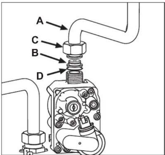
fig. 22
Validation du mode TEST
fig. 23 - Mode TEST (puissance chauffage = 100%)
Excludere boiler (economy)
fig. 21

fig. 22
(*) 30% p13% p14% p15% p16% p17% p18% p19% p20% p21% p22% p23% p24% p25% p26% p27% p28% p29% p30% p31% p32% p33% p34% p35% p36% p37% p38% p39% p40% p41% p42% p43% p44% p45% p46% p47% p48% p49% p50% p51% p52% p53% p54% p55% p56% p57% p58% p59% p60% p61% p62% p63% p64% p65% p66% p67% p68% p69% p70% p71% p72% p73% p74% p75% p76% p77% p78% p79% p80% p81% p82% p83% p84% p85% p86% p87% p88% p89% p90% p91% p92% p93% p94% p95% p96% p97% p98% p99% p100%
мал. 21

мал. 22

OFFSET = 40

рис. 21

рис. 22
EN THE CE MARKING CERTIFIES THAT THE PRODUCTS MEET THE ESSENTIAL REQUIREMENTS OF THE RELEVANT DIRECTIVES IN FORCE. THE DECLARATION OF CONFORMITY MAY BE REQUESTED FROM THE MANUFACTURER.
FR LE MARQUAGE << ATTESTE QUE LES PRODUITS SONT CONFORMES AUX EXIGENCES ESSENTIELLES DE L'ENSEMBLE DES DIRECTIVES QUI LEURS SONT APPLICABLES. LA DÉCLARATION CE DE CONFORMITÉ PEUT ÊTRE DEMANDÉE AU FABRICANT.
RO MARCAJUL C€ CERTIFICĂ FAPTUL CĂ PRODUSELE ÎNDEPLINESC CERINȚELE DE BAZĂ ALE DIRECTIVELOR RELEVANTE ÎN VIGOARE. DECLARAȚIA DE CONFORMITATE POATE FI SOLICITATĂ DE LA PRODUCĂTOR.

- BLUEHELIX TECH S 45H
- CE EAC
- OPERATING INSTRUCTIONS
- 2.1 INTRODUCTION
- PANEL - LEGEND FIG. 1
- INDICATION DURING OPERATION
- HEATING
- DOMESTIC HOT WATER (DHW)
- FAULT
- 2.3 CONNECTION TO THE POWER SUPPLY, SWITCHING ON AND OFF
- BOILER ELECTRICALLY POWERED
- SWITCHING THE BOILER OFF AND ON
- 2.4 ADJUSTMENTS
- SUMMER/WINTER SWITCHOVER
- HEATING TEMPERATURE ADJUSTMENT
- DHW TEMPERATURE ADJUSTMENT
- ROOM TEMPERATURE ADJUSTMENT (WITH OPTIONAL ROOM THERMOSTAT)
- ROOM TEMPERATURE ADJUSTMENT (WITH OPTIONAL REMOTE TIMER CONTROL)
- HOT WATER TANK EXCLUSION (ECONOMY)
- SLIDING TEMPERATURE
- ADJUSTMENTS FROM REMOTE TIMER CONTROL
- SYSTEM WATER PRESSURE ADJUSTMENT
- INSTALLATION
- 3.1 GENERAL INSTRUCTIONS
- 3.2 PLACE OF INSTALLATION
- 3.3 PLUMBING CONNECTIONS
- IMPORTANT
- ANTIFREEZE SYSTEM, ANTIFREEZE FLUIDS, ADDITIVES AND INHIBITORS
- WATER SYSTEM CHARACTERISTICS
- CONNECTION TO A STORAGE TANK FOR DOMESTIC HOT WATER PRODUCTION
- 3.4 GAS CONNECTION
- 3.5 ELECTRICAL CONNECTIONS
- ROOM THERMOSTAT (OPTIONAL)
- ACCESSING THE ELECTRICAL TERMINAL BLOCK
- 3.6 FUME DUCTS
- CONNECTION WITH COAXIAL PIPES
- 3.7 CONDENSATE DRAIN CONNECTION
- SERVICE AND MAINTENANCE
- 4.1 ADJUSTMENTS
- TEST MODE ACTIVATION
- HEATING POWER ADJUSTMENT
- 4.2 STARTUP
- BEFORE LIGHTING THE BOILER
- CHECKS DURING OPERATION
- 4.3 MAINTENANCE
- OPENING THE FRONT PANEL
- PERIODICAL CHECK
- 4.4 TROUBLESHOOTING
- DIAGNOSTICS
- TABLE OF FAULTS
- TECHNICAL DATA AND CHARACTERISTICS
- R??PRO?U?T?FI?HE
- FR
- DISPOSITIONS GÉNÉRALES
- 3.4 RACCORDEMENT GAZ
- VALIDATION DU MODE TEST
- EXCLUDERE BOILER (ECONOMY)
Brand : FERROLI
Model : Bluehelix Tech S 45 H
Category : Central heating boiler