B450 - Grass trimmer Shindaiwa - Free user manual and instructions
Find the device manual for free B450 Shindaiwa in PDF.

User questions about B450 Shindaiwa
0 question about this device. Answer the ones you know or ask your own.
Ask a new question about this device
Download the instructions for your Grass trimmer in PDF format for free! Find your manual B450 - Shindaiwa and take your electronic device back in hand. On this page are published all the documents necessary for the use of your device. B450 by Shindaiwa.
USER MANUAL B450 Shindaiwa
natural_image
Grid of 16 black squares with white borders, no text or symbols presentSHINDAIWA OWNER'S/OPERTOR'S MANUAL
B450 BRUSHCUTTER

natural_image
3D rendering of a manual tool with a mounted machine and metal spoke (no text or symbols visible)CE
shindaiwa®

WARNING!
Read this manual and familiarize yourself with its contents. This machine is designed for cutting grass, weed, and bushes.
Do not use this machine for other purposes.
Minimize the risk of injury to yourself and others.
Do not operate or service this machine unless you clearly understand this manual.
Keep this manual at a particular place so that you can reread it whenever you have a question about its use.
Introduction
Shindaiwa 450-series hand held power equipment has been designed and built to deliver superior performance and reliability without compromise to quality, comfort, safety or durability.
Shindaiwa's high-performance engines represent the leading edge of 2-cycle engine technology, delivering exceptionally high power with remarkably low displacement and weight. As an owner/operator, you'll soon discover for yourself why Shindaiwa is simply in a class by itself!
IMPORTANT!
The information contained in this owner's/ operator's manual describes units avail- able at the time of publication.
YAMABIKO corporation reserves the right to make changes to products without prior notice, and without obligation to make alterations to units previously manufactured.
Contents
Page
Attention Statements ......2
General Safety Instructions ....3
Safety Labels ....5
Checking Unit Condition ....5
Unit Description ......6
Specifications ......6
Assembly Procedure 7
Mixing Fuel 11
Starting the Engine 12
Stopping the Engine ....13
Engine Idle Adjustment ....13
Shoulder Strap/Harness ....13
Operation 14
Using a Brushcutter With a Trimmer Head ....15
Maintenance....15
Long Term Storage ....17
Blade Sharpening ....17
Troubleshooting Guide ......18
Declaration of Conformity ......21
Attention Statements
Throughout this manual are special attention statements.

WARNING!
A statement preceded by the triangular attention symbol and the word "WARNING" contains information that should be acted upon to prevent serious bodily injury.
CAUTION!
A statement preceded by the word "CAUTION" contains information that should be acted upon to prevent mechanical damage.
IMPORTANT!
A statement preceded by the word "IMPORTANT" is one that possesses special signifi cance.
NOTE:
A statement preceded by the word "NOTE" contains information that is handy to know and may make your job easier.

Read and follow this operators manual. Failure to do so could result in serious injury.

Wear head, eye, and hearing protection during the operation of this machine.

Wear non-slip gloves, long trousers and non-skid boots during the operation of this machine.

make sure no one is within 15 meters os an operating machine.

Beware of thrown objects.

MAX 8500min ^-1

The maximum speed of the cutting attachment shaft in min ^-1 .
Sound Power Level (measured in accordance with 2000/14/EC)
IMPORTANT!
The operational procedures described in this manual are intended to help you get the most from unit as well as to protect you and others from harm. These procedures are guidelines for safe operation under most conditions, and are not intended to replace any safety rules and/or laws that may be in force in your area. If you have questions regarding your Shindaiwa power tool, or if you do not understand something in this manual, your Shindaiwa dealer will be glad to assist you.
Work Safely
Trimmers and brushcutters operate at very high speeds and can do serious damage or injury if they are misused or abused. Never allow a person without training or instruction to operate this unit!

WARNING!
Never make unauthorized attachment installations.

WARNING!
Use Good Judgment
NEVER run the engine when transporting the unit.
NEVER run the engine indoors! Make sure there is always good ventilation. Fumes from engine exhaust can cause serious injury or death.
ALWAYS use the proper cutting tool for the job.
ALWAYS stop the unit immediately if it suddenly begins to vibrate or shake. Inspect for broken, missing or improperly installed parts or attachments.
NEVER extend trimming line beyond the length specified for your unit.
ALWAYS keep the unit as clean as practical. Keep it free of loose vegetation, mud, etc.
ALWAYS hold the unit firmly with both hands when cutting or trimming, and maintain control at all times.
ALWAYS keep the handles clean.
ALWAYS disconnect the spark plug wire before performing any maintenance work.
ALWAYS, if a saw blade should bind fast in a cut, shut off the engine immediately. Push the branch or tree to ease the bind and free the blade.
Stay Alert
You must be physically and mentally fit to operate this unit safely.

WARNING!
Never operate power equipment of any kind if you are
tired or if you are under the influence of alcohol, drugs, medication or any other substance that could affect your ability or judgement.
The Properly Equipped Operator

text_image
Wear hearing protection devices and a broad-brimmed hat or helmet. Always wear eye protection such as goggles or safety glasses to shield against thrown objects. Wear close-fi tting clothing to protect legs and arms. Gloves offer added protection and are strongly recommended. Do not wear clothing or jewelry that could get caught in machinery or underbrush. Secure long hair so that it is above shoulder level. NEVER wear shorts! Always wear a harness when operating a unit equipped with a blade. Always operate with both hands firmly gripping the unit. When operating with a blade, make sure the handle is positioned to provide you with maximum protection from contacting the blade. Keep a proper footing and do not overreach. Maintain your balance at all times during operation. Always make sure the appropriate cutting attachment shield is correctly installed and in good condition. Wear appropriate footwear (non-skid boots or shoes): do not wear open-toed shoes or sandals. Never work barefooted! Keep away from the rotating trimmer line or blade at all times, and never lift a moving attachment above waist-high.Be Aware of the Working Environment
Avoid long-term operation in very hot or very cold weather.
If contact is made with a hard object, stop the engine and inspect the cutting attachment for damage.
Be extremely careful of slip-pery terrain, especially during rainy weather.
Be constantly alert for objects and debris that could be thrown either from the rotating cutting attachment or bounced from a hard surface.

text_image
a- y h a hard e and achment for of slip- ly during and debris m the rotating d from a hard Make sure bystanders or observers outside the 15 meter "danger zone" wear eye protection. Always make sure the appropriate cutting attachment shield is correctly installed. 15MReduce the risk of bystanders being struck by flying debris. Make sure no one is within 15 meters — that's about 16 paces — of an operating attachment.

text_image
standers outside the15 METERS
Make sure bystanders or observers outside the 15 meter "danger zone" wear eye protection.
Always make sure the appropriate cutting attachment shield is correctly installed.
Beware of a coasting blade when brushcutting or edging. A coasting blade can injure while it continues to spin after the throttle trigger is released or after the engine is stopped.
ALWAYS clear your work area of trash or hidden debris that could be thrown back at you or toward a bystander. When operating in rocky terrain or near electric wires or fences, use extreme caution to avoid contacting such items with the cutting attachment.
Safety Labels


IMPORTANT!
Safety and Operation Information Labels: Make sure all information labels are undamaged and readable. Immediately replace damaged or missing information labels. New labels are available from your local authorized Shindaiwa dealer.

natural_image
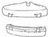
Mechanical tool with a long-handled tool and mounted device (no visible text or symbols)Checking Unit Condition

WARNING!
A cutting attachment shield or other protective device is no guarantee of protection against ricochet. YOU MUST ALWAYS GUARD AGAINST FLYING DEBRIS!
Use only authorized Shindaiwa parts and accessories with your Shindaiwa brushcutter. Do not make modifications to this unit without the written approval of YAMABIKO corporation.
NEVER operate the unit with the cutting attachment shield or other protective devices (harness, ignition switch, blade retention clip, etc.) removed!
ALWAYS make sure the cutting attachment is properly installed and firmly tightened before operation.
NEVER use a cracked or warped cutting attachment: If a properly installed attachment vibrates, replace the attachment with a new one and re-check.
ALWAYS stop the engine immediately and check for damage if you strike a foreign object or if the unit becomes tangled. Do not operate with broken or damaged equipment.
NEVER allow the engine to run at high RPM without a load. Doing so could damage the engine.
NEVER operate a unit with worn or damaged fasteners or attachment holders.
NEVER cut with a dull blade. Doing so will increase the risk of blade thrust and may also cause equipment damage.
Unit Description
Using the accompanying illustrations as a guide, familiarize yourself with this unit and its various components. Understanding the product helps ensure top performance, long service life, and safer operation.

WARNING!
Do not make unauthorized modifications or alterations to any of these units or their components.

text_image
Gearcase Cutting Attachment Shield Outer Tube Handlebar Throttle Trigger Ignition Switch Spark Plug Air Filter Tank Guard Fuel Tank Shoulder HarnessSpecifications
| Model Name | B450/EC1 |
| Engine Model | S450EC1 |
| Engine Type | 2-cycle, vertical cylinder, air cooled |
| Displacement | 41.5 cm3 |
| Bore and Stroke | 40 x 33 mm |
| Maximum Power Output | 1.6 kW |
| Engine Speed at Idling | 2,750 min-1 |
| Maximum Engine Speed | 11,500 min-1 |
| Engine Speed at Maximum Power Output | 7,500 min-1 |
| Dry Weight (Without cutting attachment and guard.) | 7.7 kg |
| Dimensions (L x W x H) mm | 1795x565x475 |
| Fuel Tank Capacity | 760 cm3 |
| Fuel/Oil Ratio | 50:1 |
| Carburetor Type | TK, DPV11W, Diaphragm |
| Ignition | Fully electronic, transistor controlled |
| Spark Plug | NGK BMR6A |
| Air Cleaner Type | Semi-wet |
| Starting Method | Recoil Starter |
| Stopping Method | Slide Switch |
| Handle Type | Bicycle Handlebar |
| Sound Pressure Level* (average data between at Idling and at Racing) Note 1 | 92 dB (A) |
| Sound Power Level** (average data between at Idling and at Racing) Note 1 | 107 dB (A) |
| Vibration Level*** Note 1 | Idling (Left/Right) 3.4/2.2 m/s2 |
| Racing (Left/Right) 4.7/3.5 m/s2 | |
| Sound Pressure Level* (average data between at Idling and at WOT) Note 2 | 96 dB (A) |
| Sound Power Level** (average data between at Idling and at WOT) Note 2 | 112 dB (A) |
| Vibration Level*** Note 2 | Idling (Left/Right) 1.5/1.3 m/s2 |
| WOT (Left/Right) 3.4/3.6 m/s2 |
* Sound Pressure Level: In accordance with EN ISO 11806 and ISO 7917
** Sound Power Level In accordance with EN ISO 11806 and ISO 10884
*** Vibration Level: In accordance with EN ISO 11806 and ISO 7916
Note 1: 8-tooth blade equipped. Note 2: Trimmer head equipped.
Assembly Procedure
Prior to Assembly
Before assembling, make sure you have all the components required for a complete unit:
■ Engine assembly
■ Outer tube assembly
■ Cutting attachment shield
■ Cutting attachment
■ Handlebar
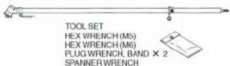
Kit containing cutting attachment shield mounting bracket and hardware, operator's handle mounting bracket and hardware, gearcase tool holder, this manual and tool kit for routine maintenance. Tool kits vary by model and may include a hex wrench, spanner and a combination spark plug wrench/screw-driver.
Carefully inspect all components for damage.
Assembling the Outer Tube
Assembly of the Outer Tube
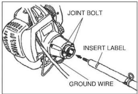
(1) Loosen the 2 joint bolts fully and slip the outer tube into the joint until the tube bottoms (up to the insert label). The outer tube or gearcase shaft may have to be rotated slightly for the splines on the mainshaft to fully engage the engine.
(2) Attach the ground wire to the joint bolt.
(3) Tighten the 2 joint bolts securely.
text_image
JOINT BOLT INSERT LABEL GROUND WIREENGINE ASSEMBLY
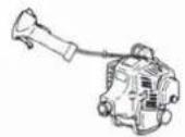
OUTER TUBE ASSEMBLY
text_image
TOOL SET HEX WRENCH (M5) HEX WRENCH (M6) PLUG WRENCH, BAND × 2 SPANNER WRENCHDEBRIS SHIELD
HANDLEBAR

HARNESS

BLADE COVER

IMPORTANT!
The terms "left", "left-hand", and "LH"; "right", "right-hand", and "RH"; "front" and "rear" refer to directions as viewed by the operator during normal operation.
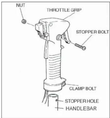
(4) Loosen the stopper bolt of the throttle grip. Remove the stopper bolt and nut.
(5) Fully loosen the clamp bolt of the throttle grip.
text_image
NUT THROTTLE GRIP STOPPER BOLT CLAMP BOLT STOPPER HOLE HANDLEBAR(6) Slip the right-side handlebar into the throttle grip. Locate the throttle grip so that the stopper bolt can pass through the stopper hole.
Securely tighten the stopper bolt and nut.
(7) Securely tighten the clamp bolt.
Assembly of the Handle
(1) Loosen the two bolts of the lower cap and remove the lower cap.
(2) Position the handle bracket against the handle label located on the outer tube.
(3) Attach the lower cap with the two bolts and tighten the bolts. Make sure the front handle is in position per the illustration.
(4) Secure the cable to the outer pipe with the two bands as the illustration shows. The two bands are in the tool bag.

text_image
HANDLEBAR HANDLE BRACKET HANDLE LABEL BOLT LOWER CAP THROTTLE GRIP
text_image
BANDThrottle Cable Adjustment
(1) Pull the throttle trigger gently, and check for free-play of approximately 5mm.
(2) If free-play is out of specifications:
(a) Slide the cable cap toward the muffler side until the adjusting nut and the lock nut appear.
(b) Loosen the lock nut slightly.
(c) Turn the adjusting nut so that free-play is about 5mm.
(d) Then, tighten the lock nut.
(e) Slide the cable cap back.

text_image
FREE PLAY = 5mm
text_image
THROTTLE CABLE CABLE CAP ADJUSTING NUT LOCK NUTCutting Attachment Shield Assembly

WARNING!
NEVER operate this machine without the cutting attachment shield. Operating without the cutting attachment shield may result in serious injury.
(A) Cutting Attachment Shield
(1) Insert the cutting attachment shield between the outer tube and the lower clamp. Loosen the nut and bolt which are tightening the lower clamp if the cutting attachment shield does not fit with the lower clamp.
NOTE:
It may be necessary to loosen the lower clamp bolt so that the shield will fit between the tube and clamp.
(2) The upper clamp over the outer pipe and tighten with four bolts.
NOTE:
Tighten four bolts a crisscross fashion.
(3) Tighten the lower clamp bolt and nut securely.

WARNING!
Carefully inspect the cutting attachment shield assembly to make sure it is tightened securely and does not wobble.
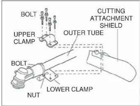
text_image
BOLT UPPER CLAMP BOLT NUT LOWER CLAMP OUTER TUBE CUTTING ATTACHMENT SHIELD(B) Shield Extension (when trimmer head is in use)
(Consult your dealer.)
(1) Attach the shield extension to the cutting attachment shield.
(2) Be sure to tighten the bolt.
NOTE:
Make sure the shield extension is completely hooked at the hook receiver.
CAUTION!
The line cutter is attached to the shield extension and must be used when operating with a trimmer head.
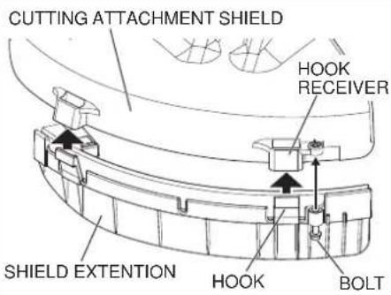
text_image
CUTTING ATTACHMENT SHIELD HOOK RECEIVER SHIELD EXTENTION HOOK BOLTInstalling a Blade
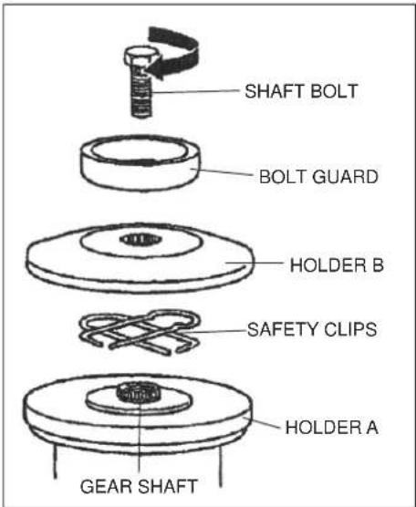
(1) Make sure the switch is off and the engine is stopped.
(2) Wear gloves to protect your hands.
(3) Turn the unit over so the saw holder fl ange extending from the gear case is facing up.
(4) Using the small end of the plug wrench, loosen the bolt (turn clockwise) and remove the bolt, bolt guard, and holder B.
(5) Slide the safety clip as shown in the illustration.
text_image
SHAFT BOLT BOLT GUARD HOLDER B SAFETY CLIPS HOLDER A GEAR SHAFT
text_image
WARNING! Never operate this machine without the safety clip in place.(6) Fit the blade over the safety clip onto holder A. Then, slide the safety clip back to its original position.

text_image
WARNING! The blade must fit flat against holder A. The blade's mounting hole must be centered over the raised boss of holder A.(7) Put holder B and bolt guard back and at this time only fi nger tighten the bolt. Make sure holder B is fl at against the blade and the recess in holder B must face the blade and completely cover the safety clip.
(8) Rotate holder A until the hole in its skirt aligns with the hole in the gear case. Insert the hex wrench through both holes (to prevent the shaft from turning).
(9) Holding the hex wrench and blade with one hand, tighten the bolt (turn counterclockwise) securely using the hex socket end of the plug wrench.
(10) Remove the hex wrench.

text_image
WARNING! Before operating, make sure the blade is securely mounted. Turn the blade with your hand slightly and make sure the blade turns smoothly without wobbling.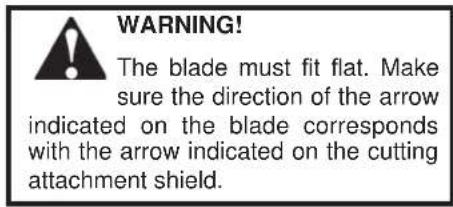
text_image
WARNING! The blade must fit flat. Make sure the direction of the arrow indicated on the blade corresponds with the arrow indicated on the cutting attachment shield.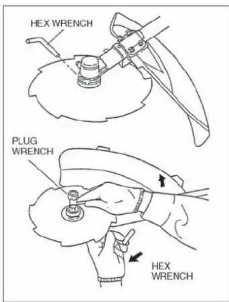
text_image
HEX WRENCH PLUG WRENCH HEX WRENCH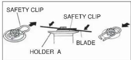
text_image
SAFETY CLIP SAFETY CLIP HOLDER A BLADE
WARNING!
Minimize the risk of fi re, burns, and personal injury!
■ STOP engine before refueling.
■ ALWAYS allow the engine to cool before refueling
■ ALWAYS open the fuel cap slowly to allow any pressure build-up in the tank to release fuel vapor slowly.
■ ALWAYS transport and store fuels in an approved container.
■ Avoid overfilling and wipe-up all spilled fuel. Move the engine at least 3 meters from the fueling point, storage area, and other readily fl ammable materials before restarting.
■ ALWAYS inspect the unit for fuel leaks before each use. During each refi ll, make sure there are no fuel leaks around the fuel cap and/or tank. If a fuel leak is evident, stop using the unit immediately. Fuel leaks must be repaired before using the unit.
■ NEVER smoke or light any fires near the engine or fuel source.
■ NEVER place any flammable material near the engine or muffler.
■ NEVER operate the engine without the muffler in good working condition.
■ ALWAYS move the unit to a place well away from a fuel storage area or other readily fl ammable materials before starting the engine.
CAUTION!
This engine is designed to operate on a 50:1 mixture consisting of unleaded gasoline and a premium 2-cycle mixing oil only. Use of Non-approved mixing oils can lead to excessive maintenance costs and/or engine damage.
CAUTION!
Some gasolines contain alcohol as an oxygenate! Oxygenated fuels may cause increased operating temperatures. Under certain conditions, alcohol-based fuels may also reduce the lubricating qualities of some mixing oils. Never use any fuel containing more than 10% alcohol by volume! Generic oils and some outboard motor oils may not be intended for use in high-performance air cooled 2-cycle engines, and should never be used in your Shindaiwa engine!
Filling The Fuel Tank
IMPORTANT!
Mix only enough fuel for your immediate needs! If fuel must be stored longer than 30-days, it should first be treated with a stabilizer such as StaBil™ or equivalent product!
■ Use only fresh, clean unleaded gasoline with a pump octane rating of 87 or higher.
■ Mixing fuel with a Premium 2-cycle mixing oil designed for use with high-performance 2-cycle air-cooled engines.
■ Refer to the following examples of 50:1 fuel to oil mix quantities:
| Gasoline liters | 2-cycle mixing oil milliliters |
| 2.5 l | 50 ml |
| 5 l | 100 ml |
| 10 l | 200 ml |
| 20 l | 400 ml |
CAUTION!
Never attempt to mix fuel in the unit's fuel tank. Always mix all fuels in a clean approved container.
- Place the unit on a flat, level surface, and wipe any debris from around the fuel cap.
- Remove the fuel cap.
- Fill the tank with clean, fresh fuel. It is not permitted to fi ll fuel above the shoulder level of fuel tank.
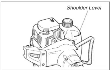
text_image
Shoulder Level- Replace the cap, and wipe away any spilled fuel before starting the engine.
Starting the Engine

WARNING!
MAKE SURE THE BLADE IS WELL CLEAR OF ANY INTERFERENCE. Before starting the engine, place unit on clear, level surface. Make sure you have good secure footing and always keep a fi rm grip on the machine. THE CUTTING ATTACHMENT MAY ROTATE WHEN THE ENGINE STARTS.

WARNING!
Move at least three meters away from the fuel site before starting the engine.

WARNING!
Never operate the engine without the cutting attachment installed.
Starting a Cold Engine and/or Re-starting After Refueling.
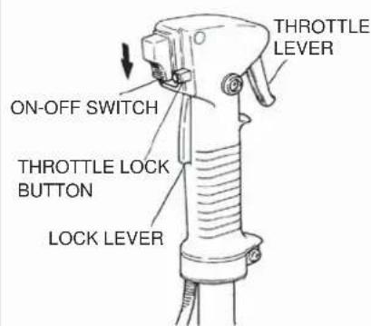
text_image
ON-OFF SWITCH THROTTLE LOCK BUTTON LOCK LEVER THROTTLE LEVER(a) Slide the ON-OFF switch to the "I" position.
(b) Prime the engine by repeatedly depressing the carburetor primer bulb until fuel can be seen fl owing through the transparent overflow return tube:

text_image
CHOKE LEVER PRIMER BULB OVERFLOW TUBE(c) Push the choke lever upward ("closed" position). (Cold engine.)

text_image
Make sure the cutting attachment is clear of obstructions.(d) Depressing the lock lever, pull the throttle lever fully and depress the throttle lock button. While depressing the throttle lock button, release the throttle lever and the lock lever. Now the throttle stays at high idle (starting speed).
(e) While firmly holding the outer tube with one hand, pull the recoil starter handle upward with your other hand. Pull slowly at first until you feel the starter engage, then pull quickly to start the engine. Do not pull the starter rope to the end of its travel.
CAUTION!
Pulling the starter rope to the end of its travel may damage the starter mechanism.
IMPORTANT!
Repeated cranking of the engine with the choke CLOSED ("|") will lead to engine fl ooding. If the engine fails to start after several attempts, move the choke lever to the OPEN position and continue cranking.
(f) When the engine first fires, gradually return the choke to OPEN
("|+1") position if you have not already done so.
- If the engine stops before the choke is fully open, restart with the choke closed.
- If the engine stops after the initial fi ring, restart with choke closed.
(g) When the engine starts and is running, set the engine to idle by tapping the throttle lever to release the throttle lock.

WARNING!
Never start the engine from the operating position.
Starting a Warm Engine
Starting a warm engine involves all of the steps of starting a cold engine. EXCEPT:
- The choke should be in the OPEN position.
If the engine does not start, follow the cold engine starting procedure.
When the engine starts:
- After the engine starts, disengage the throttle lock and allow the engine to warm-up at idle for 2 or 3 minutes before operating the machine. - After the engine is warm, pick up the machine and clip-on the strap. - Advancing the throttle makes the cutting attachment rotate faster; releasing the throttle makes the attachment stop running. If the cutting attachment continues to rotate, carburetor idle speed should be adjusted.
(See next page.)
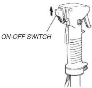
Stopping the Engine
Idle the engine briefly before stopping, then slide the ON-OFF switch to the "O" (for STOP) position.

WARNING!
The cutting attachment continues rotating for a while after the switch is turned off.
text_image
ON-OFF SWITCHEngine Idle Adjustment
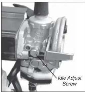
The engine must return to idle speed whenever the throttle lever is released. Idle speed is adjustable, and must be set low enough to permit the engine clutch to disengage the cutting attachment when the throttle is released.

WARNING!
The cutting attachment must NEVER rotate at engine idle! If the idle speed can not be adjusted by the procedure described here, have the unit inspected at an authorized Shindaiwa dealer.
text_image
Idle Adjust Screw(1) Place the unit on the ground, then start the engine and allow it to idle for 2-3 minutes until warm.
(2) If the attachment rotates when the engine is at idle, reduce the idle speed by turning the idle adjustment screw counterclockwise.
(3) If a tachometer is available, the engine idle speed should be adjusted to 2,750 min ^-1 (rpm)
NOTE:
Carburetor fuel mixture adjustments are preset at the factory on units with emission control systems and cannot be serviced in the fi eld.
Shoulder Strap/Harness
To Wear the Strap
(1) Attach the strap hook to the hanger on the outer pipe.
(2) Wear the strap so that the hook stays at your right side.
(3) Adjust the length of the strap so that you can hold and operate the machine comfortably.
(4) Make sure the hip pad stays between your hip and outer pipe.
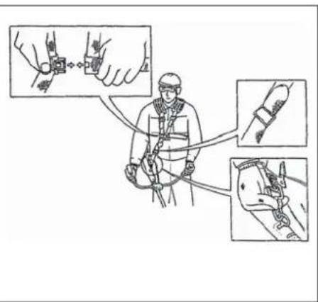
text_image
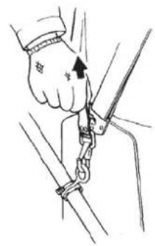
Diagram illustrating safety harness installation steps with labeled diagrams showing hand placement and cable installation detailsEmergency Release
In case of emergency, firmly pull the white tab at the hook. The machine will release from the strap.
natural_image
Illustration of a hand using a tool to lift a rope, showing the angle of motion (no text or symbols present)IMPORTANT!
Adjust the shoulder strap so the shoulder pad rests comfortably on the off-side shoulder and the cutting path of the cutting attachments is parallel to the ground. Make sure all hooks and adjustment devices are secure.

WARNING!
Always wear a harness when operating this unit with a blade.
NOTE:
Using a harness with a bruscutter allows you to maintain proper control of the unit and reduces fatigue during extended operation.
Double Shoulder Harness
Adjust the double shoulder harness straps so the shoulder pads rest comfortably on the offside of the shoulder and the cutting path of the blade is parallel to the ground. Make sure all hooks and adjusting devices are secure.

natural_image
Line drawing of a mechanical device with no visible text or symbolsOperation
Using A Blade
(1) After starting the engine, pull the throttle lever gradually. The engine speed increases and the blade will start rotating.
(2) When the throttle lever is released, the engine goes back to idle speed automatically.
(3) Operate the machine at full throttle while cutting. Best fuel efficiency is obtained by releasing the throttle when swinging back after cut.
(4) The blade rotates counterclockwise. For best performance and to minimize being stuck by debris, move the blade from right to left while advancing on your work.

WARNING!
Position the blade so cuts are made between blade's 8 o'clock and 10 o'clock as (as viewed from above). T cut between the 11 o'clock 'clock positions.

WARNING!
"BLADE THRUST" is a sudden sideway or backward motion of the machine. Such motion may occur when the blade jams or catches on an object such as a sapling tree or tree stump. BE CONSTANTLY ALERT FOR BLADE THRUST AND GUARD AGAINST ITS EFFECTS.
CAUTION!
DO NOT use 2-tooth blades with this machine.
CAUTION!
To prevent possible engine damage, do not allow the machine to run at high speeds without a load. Avoid operating the engine at low speeds. Doing so can lead to rapid clutch wear. In addition, slow-speed operation tends to cause grass and debris to wrap around the cutting attachment.
natural_image
Simple line drawing of a person using a tool to lift a wall, with arrows indicating direction (no text or symbols)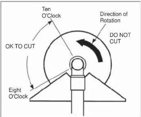
text_image
Ten O'Clock Direction of Rotation DO NOT CUT OK TO CUT Eight O'Clock
WARNING!
NEVER strike or slam the spinning blade against the wood.

WARNING!
When transporting, make sure the engine is not running and blade is covered with blade cover.
Recommended Cutting Attachments
Make sure to use the following recommended Shindaiwa cutting attachment with this machine.
Blades
PART NUMBER X405-000350
8-TOOTH BLADE
INNER BORE: 25.4mm
DIAMETER: 255.0mm
THICKNESS: 2.0mm

PART NUMBER X405-000151
3-TOOTH BLADE
INNER BORE: 25.4mm
DIAMETER: 255.0mm
THICKNESS: 3.0mm

PART NUMBER X405-000330
4-TOOTH BLADE
INNER BORE: 25.4mm
DIAMETER: 255.0mm
THICKNESS: 2.2mm

Trimmer Heads
PART NUMBER 78820-14000
SEMI-AUTOMATIC TRIMMER HEAD
BOLT DIAMETER: 10mm
THREAD: LEFT,1.25mm PITCH

Using a Brushcutter With a Trimmer Head
You may install one of several types of Shindaiwa trimmer heads on your B450 brushcutter, each with features for specific applications and/or operational requirements.
For proper operation, always refer to the instructions accompanying the trimmer head being used. Available trimmer head styles include:
■ Semi-automatic. Trimmer line is indexed when the operator taps the trimmer head on the ground during operation.
■ Manual. The operator indexes line manually with the grass trimmer stopped.
■ Fixed. The operator must stop the unit and add new lengths of trimmer line manually.
■ Flail. This device, designed for clearing weeds and light brush, features three nylon blades attached to the head by pivots.
CAUTION!
Do not push the rotating line into trees, wire fences or any material that could tangle or break line ends.
Engine Operating Speeds
Operate at full throttle while cutting grass.
CAUTION!
Operation at low rpm can lead to premature clutch failure.
Trimming and Mowing Grass
Hold the grass trimmer so the trimmer head is angled slightly into the area to be cut. To ensure maximum trimmer-line service life, cut only with the tip of the trimmer line. Cut grass by swinging the unit's trimmer head from left to right. Keep the trimmer head horizontal.
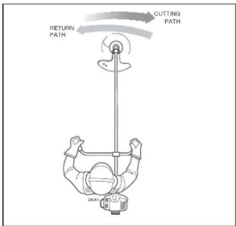
text_image
RETURN PATH CUTTING PATH 25041Edging
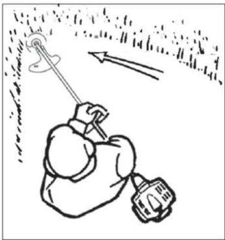
Tilt the handle about 100^ to the left (from horizontal) and move forward, holding the trimmer or brushcutter vertically as shown.

natural_image
Line drawing of a worker using a metal detector (no text or symbols)Maintenance

WARNING!
Before performing any maintenance, repair, or cleaning work on the machine, make
sure the engine and cutting attachment are completely stopped. Disconnect the spark plug wire before performing service or maintenance work.

WARNING!
er repair a damaged
blade by welding, straighten-by modifying its shape. An blade may break during op-, resulting in serious personal
Daily Maintenance
Prior to each work day, perform the following:
■ Remove the dirt and debris from the engine, check the cooling fi ns and air cleaner for clogging, and clean them as necessary.
■ Carefully remove any accumulations of dirt or debris from the muffler and fuel tank. Dirt buildup in these areas can lead to engine overheating, fire, or premature wear.
- Check for loose or missing screws or components. Make sure the cutting attachment is securely fastened.
■ Check the machine for leaking fuel or grease.
10 Hour Maintenance
Remove the air cleaner element from the carburetor and clean it thoroughly with soap and water. Squeeze out excess, let dry and reassemble the element.
CAUTION!
Do not operate the machine if the air cleaner or element is damaged, or if the element is water-soaked.
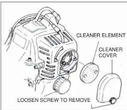
text_image
CLEANER ELEMENT CLEANER COVER LOOSEN SCREW TO REMOVE10/15 Hour Maintenance
Remove and clean the spark plug. Adjust the spark plug electrode gap to 0.6 - 0.7mm. If the plug must be replaced, use only NGK BMR6A.
CAUTION!
Before removing the spark plug, clean the area around the plug to prevent dirt and dust from getting into the engine's internal parts.
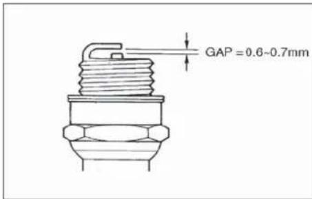
text_image
GAP = 0.6~0.7mm50 Hour Maintenance
Cleaning
Remove and clean the cylinder cover and clean grass and dirt from the cylinder fi ns.
Remove the cutting attachment and the gear shaft collar, and press new grease into the gear case until the old grease has been pushed out. Use only lithium base grease (such as Shindaiwa Gear Case Lubricant).
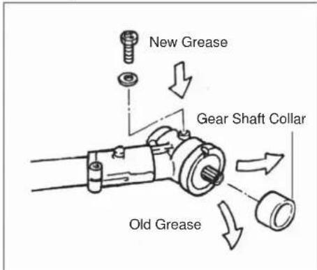
text_image
New Grease Gear Shaft Collar Old GreaseFuel Filter Maintenance
Use a hooked wire to extract the fuel fi liter from inside the fuel tank. Remove and replace the fi liter element. Before reinstalling the fi liter, inspect the condition of the fuel line. If damage or deterioration are noted, the unit should be removed from service until you can consult with an authorized servicing dealer.
CAUTION!
Make sure you do not pierce the fuel line with the end of the hooked wire. The line is delicate and can be damaged easily.

text_image
Hooked WireMuffl er Maintenance
WARNING!
Other operate this unit with a damaged or missing muffler! Operating with missing or damaged exhaust components is a fi re hazard and may also damage your hearing.
IMPORTANT!
Do not remove the muffler cover. If necessary, Please consult your dealer.
If carbon deposits are severe or if no performance improvement is noted, your unit should be returned to your Shindaiwa dealer for inspection.
Long Term Storage
Whenever the unit will not be used for 30 days or longer, use the following procedures to prepare it for storage:
■ Clean external parts thoroughly and apply a light coating of oil to all metal surfaces.
■ Drain all the fuel from the fuel tank.
IMPORTANT!
All stored fuels should be stabilized with a fuel stabilizer such as STA-BIL ^TM .
To remove the remaining fuel from the fuel lines and carburetor and with the fuel drained from the fuel tank.
- Prime the primer bulb until no more fuel is passing through.
- Start and run the engine until stops running.
- Repeat steps 1 and 2 until the engine will no longer start.
CAUTION!
Gasoline stored in the carburetor for extended periods can cause hard starting, and could also lead to increased service and maintenance costs.
■ Remove the spark plug and pour about 7 grams of 2-cycle mixing oil into the cylinder through the spark plug hole. Slowly pull the recoil starter 2 or 3 times so oil will evenly coat the interior of the engine. Reinstall the spark plug.
■ Before storing the unit, repair or replace any worn or damaged parts.
■ Remove the air cleaner element from the carburetor and clean it thoroughly with soap and water. Let dry and reassemble the element.
■ Store the unit in a clean, dust-free area.
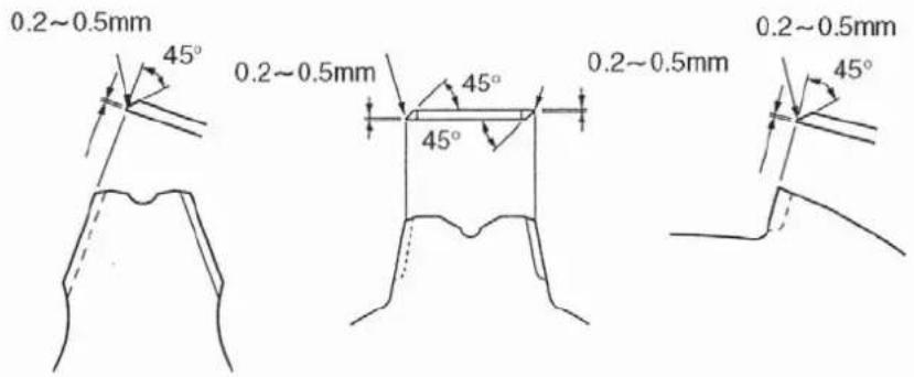
Blade Sharpening
With the file or a grinder, file a blade as follows.

Sharpen only the cutting teeth of a blade. DO NOT alter the contour of the blade in any way. In order to keep the blade in balance, all cutting edges must be sharpened equally. DO NOT fi le the tips of the teeth too sharp.
Make sure the width of the 3 sides/4 sides is all the same.

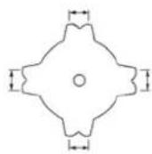
The sharpening angle should be 45^ approx. Do not file the tips of the blade too sharp. Leave 0.2\~0.5mm unsharpened.
text_image
0.2~0.5mm 45° 0.2~0.5mm 45° 0.2~0.5mm 45° 0.2~0.5mmThe bottom of each tooth must remain unsharpened. (Blade as viewed from bottom)

natural_image
Simple line drawing of a garment pattern with a checkmark (no text or symbols)4-Tooth Blade

natural_image
Simple line drawing of a mechanical part with a prohibition symbol (no text or labels)
text_image
2. Tensile Block8-Tooth Blade

text_image
Technical diagram showing a bent pipe with dimension arrows and a prohibition symbolEngine Does Not Start
What To Check Possible Cause Remedy
flowchart
graph TD
    A["Does the engine crank?"] -->|NO| B["Faulty recoil starter. Fluid in the crankcase. Internal damage."]
    A -->|YES| C["Good compression?"]
    C -->|NO| D["Loose spark plug. Excess wear on cylinder, piston, rings."]
    C -->|YES| E["Does the tank contain fresh fuel of the proper grade?"]
    E -->|NO| F["Fuel incorrect, stale, or contaminated; mixture incorrect."]
    E -->|YES| G["Is fuel visible and moving in the return line when priming?"]
    G -->|NO| H["Check for clogged fuel filter and/or vent."]
    G -->|YES| I["Is there spark at the spark plug wire terminal?"]
    I -->|NO| J["The ignition switch is in “O” (OFF) position. Shorted ignition ground. Faulty ignition unit."]
    I -->|YES| K["Check the spark plug."]
    K -->|NO| L["If the plug is wet, excess fuel may be in the cylinder."]
    K -->|YES| M["The plug is fouled or improperly gapped."]
    K -->|YES| N["The plug is damaged internally or of the wrong size."]
    N -->|No| O["Crank the engine with the plug removed, replace the plug, and re-start."]
    N -->|YES| P["Clean and re-gap the plug to 0.6 ~ 0.7 mm. Re-start."]
    N -->|YES| Q["Replace the plug with a NGK BMR6A. Re-start."]
Manufacturer
YAMABIKO CORPORATION
7-2 SUEHIROCHO 1-CHOME, OHME, TOKYO 198-8760, JAPAN
Authorized Representative in Europe
Atlantic Bridge Limited
Atlantic House, PO Box 4800, Earley, Reading RG5 4GB, United Kingdom
Low Power Output
What To Check Possible Cause Remedy
| Is the engine overheating? | Operator is overworking the unit. | Cut at a slower rate. |
| Carburetor mixture is too lean. | Consult with an authorized servicing dealer. | |
| Improper fuel ratio. | Refill with clean fresh unleaded gasoline with a pump octane of 87 or higher, mixed with Premium 2-cycle mixing oil at a 50:1 gasoline/oil ratio. | |
| Fan, fan cover, cylinder fins dirty or damaged. | Clean, repair or replace as necessary. | |
| Carbon deposits on the piston or in the muffler. | Consult with an authorized servicing dealer. | |
| Engine is rough at all speeds. May also have black smoke and/or unburned fuel at the exhaust. | Clogged air cleaner element. | Clean or replace the air filter. |
| Loose or damaged spark plug. | Tighten or replace the plug with a NGK BMR6A. Re-start. | |
| Air leakage or clogged fuel line. | Repair or replace fuel filter and/or fuel line. | |
| Water in the fuel. | Refill with fresh fuel/oil mixture. | |
| Piston seizure. | Consult with an authorized servicing dealer. | |
| Faulty carburetor and/ or diaphragm. | Consult with an authorized servicing dealer. | |
| Engine is knocking. | Overheating condition. | See above. |
| Improper fuel. | Check fuel octane rating; check for presence of alcohol in the fuel. Refuel as necessary. | |
| Carbon deposits in the combustion chamber. | Consult with an authorized servicing dealer. |
Additional Problems
Symptom Possible Cause Remedy
| Poor acceleration. | Clogged air filter. | Clean or replace the air filter. |
| Clogged fuel filter. | Replace the fuel filter. | |
| Lean fuel/air mixture. | Consult with an authorized servicing dealer. | |
| Idle speed set too low. | Adjust: 2,750 min ^-1 | |
| Engine stops abruptly. | Switch turned off. | Reset the switch and re-start. |
| Fuel tank empty. | Refuel. See page 11. | |
| Clogged fuel filter. | Replace fuel filter. | |
| Water in the fuel. | Drain; replace with clean fuel. See page 11. | |
| Shorted spark plug or loose terminal. | Clean or replace spark plug with a NGK BMR6A. Tighten the terminal. | |
| Ignition failure. | Replace the ignition unit. | |
| Piston seizure. | Consult with an authorized servicing dealer. | |
| Engine difficult to shut off. | Ground (stop) wire is disconnected, or switch is defective. | Test and replace as required. |
| Overheating due to incorrect spark plug. | Replace spark plug with a NGK BMR6A. | |
| Overheated engine. | Idle engine until cool. | |
| Cutting attachment moves at engine idle. | Engine idle too high. | Set idle: 2,750 min ^-1 |
| Broken clutch spring or worn clutch spring boss. | Replace spring/shoes as required, check idle speed. | |
| Loose attachment holder. | Inspect and re-tighten holders securely. | |
| Excessive vibration | Warped or damaged attachment. | Inspect and replace attachment as required. |
| Loose gearcase. | Tighten gearcase securely. | |
| Bent main shaft/worn or damaged bushings. | Inspect and replace as necessary. | |
| Attachment will not rotate | Shaft not installed in powerhead or gearcase. | Inspect and reinstall as required. |
| Broken shaft. | Consult with an authorized servicing dealer. | |
| Damaged gearcase. | Consult with an authorized servicing dealer. |
The undersigned manufacturer:
YAMABIKO CORPORATION
7-2 SUEHIROCHO 1-CHOME
OHME ; TOKYO 198-8760
JAPAN
This declaration of conformity is issued under the sole responsibility of the manufacturer.
declares that the hereunder specified new unit:
BRUSHCUTTER
Brand: shindaiwa Type: B450

natural_image
Mechanical tool with mounted sensor and motor assembly (no visible text or symbols)complies with:
* the requirements of Directive 2006/42/EC (use of harmonized standard EN ISO 11806-1: 2011)
* the requirements of Directive 2004/108/EC until 19th April 2016 (use of harmonized standard EN ISO 14982: 2009) and 2014/30/EU from 20th April 2016 (use of harmonized standard EN ISO 14982: 2009)
* the requirements of Directive 2000/14/EC
Conformity assessment procedure followed ANNEX V
Measured sound power level : 115dB(A)
Guaranteed sound power level : 117dB(A)
Serial Number 9094081 \~ 9129999
36000001 and up
Tokyo, January 1st, 2016
YAMABIKO CORPORATION
Marayuki timura
The authorized Representative in Europe who is authorized to compile the technical file.
Company: Atlantic Bridge Limited
Address: Atlantic House, PO Box 4800,
Earley, Reading RG5 4GB, UK
Masayuki Kimura
General Manager Quality Assurance Dept.
Mr. Philip Wicks
MEMORANDUM
YAMABIKO CORPORATION
7-2 SUEHIROCHO 1-CHOME, OHME, TOKYO 198-8760, JAPAN
PHONE: 81-428-32-6118. FAX: 81-428-32-6145.
shindaiwa®

natural_image
Grid of 16 black squares with white horizontal and vertical white lines, no text or symbols presentnatural_image
3D rendering of a manual tool with a mounted machine and metal rod, no visible text or symbolsCE
shindaiwa®

AVERTISSEMENT!
natural_image
Mechanical tool with a mounted machine and lever mechanism (no visible text or symbols)text_image
JEU = 5 mm
text_image
CABLE D'ACCÉLÉRATION PROTECTEUR DE CÂBLE ÉCROU DE RÉGLAGE ÉCROU DE BLOCAGEnatural_image
Technical line drawing of a mechanical engine component (no text or symbols visible)text_image
Diagram illustrating safety instructions for a person using a device, with labeled diagrams showing hand gestures and rope connections.Détachement rapide
text_image
Diagram showing a hand using a cable to lift a rope, with an arrow indicating the angle of change.IMPORTANT!
natural_image
Line drawing of a mechanical device with attached straps and a clip (no text or symbols)Fonctionnement
natural_image
Simple line drawing of a person using a tool to lift a wall, with arrows indicating upward motion (no text or symbols)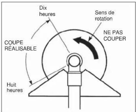
text_image
Dix heures Sens de rotation NE PAS COUPER COUPE RÉALISABLE Huit heures
AVERTISSEMENT!
natural_image
Line drawing of a worker using a metal detector (no text or symbols)Entretien

AVERTISSEMENT
!
natural_image
Two abstract geometric shapes with arrowheads, no text or symbols presentnatural_image
Simple line drawing of a garment pattern with a checkmark (no text or symbols)Lame à 4 dents

natural_image
Simple line drawing of a hood with a circular prohibition symbol (no text or labels)
natural_image
Simple line drawing with a checkmark and a dashed line, no text or symbols presentLame à 8 dents

text_image
Technical diagram showing a bent pipe with dimension arrows and a prohibition symbolAtlantic Bridge Limited
Atlantic House, PO Box 4800, Earley, Reading RG5 4GB, Royauma-Uni
Puissance insuffi sante
natural_image
Mechanical tool with a mounted spoke and circular base (no text or symbols visible)est conforme aux :
Adresse : Atlantic House, PO Box 4800,
natural_image
3D rendering of a manual tool with a mounted machine and metal rod, no visible text or symbolsCE
shindaiwa®

AVVERTENZA
natural_image
3D rendering of a manual tool with a mounted machine and circular base (no text or symbols visible)text_image
GIOCO = 5 mm
text_image
CAVO DELL'ACCELERATORE COPERCHIO DEL CAVO DADO DI REGOLAZIONE CONTRODADOnatural_image
Technical line drawing of a mechanical engine component (no text or symbols)text_image
Diagram illustrating safety harnesses with labeled diagrams showing hand placement and cable installation stepsnatural_image
Illustration of a hand using a hook to lift a rope, no text or symbols presentIMPORTANTE
natural_image
Line drawing of a mechanical device with attached straps and a clip (no text or symbols)Funzionamento
natural_image
Simple line drawing of a person using a tool to lift a wall, with arrows indicating direction (no text or symbols)
natural_image
Line drawing of a worker using a metal detector (no text or symbols)Manutenzione

AVVERTENZA
natural_image
Simple line drawing of a symmetrical mechanical or architectural component with two curved lines and a dotted line indicating a section (no text or symbols)
Lama a 4 denti

natural_image
Simple line drawing of a symmetrical abstract shape with two vertical arrows pointing to the edges (no text or symbols)

natural_image
Pure geometric line drawing with intersecting lines and a dashed vertical line (no text or symbols)
Lama a 8 denti

natural_image
Pure geometric diagram showing a curved line with arrows and a dashed rectangle, no text or symbols present.
Atlantic Bridge Limited
Atlantic House, PO Box 4800, Earley, Reading RG5 4GB, Regno Unito
natural_image
Mechanical tool with a mounted spoke and circular base (no visible text or symbols)è conforme a:
Azienda: Atlantic Bridge Limited
Indirizzo: Atlantic House, PO Box 4800,
Earley, Reading RG5 4GB, Regno Unito
Sig. Philip Wicks
MEMORANDUM
MEMORANDUM
YAMABIKO CORPORATION
7-2 SUEHIROCHO 1-CHOME, OHME, TOKYO 198-8760, GIAPPONE
TELEFONO: 81-428-32-6118. FAX: 81-428-32-6145.