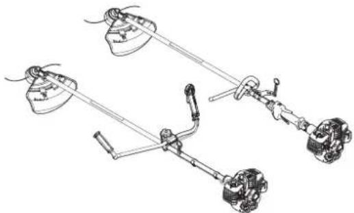
T302TS - Grass trimmer Shindaiwa - Free user manual and instructions
Find the device manual for free T302TS Shindaiwa in PDF.


User questions about T302TS Shindaiwa
0 question about this device. Answer the ones you know or ask your own.
Ask a new question about this device
Download the instructions for your Grass trimmer in PDF format for free! Find your manual T302TS - Shindaiwa and take your electronic device back in hand. On this page are published all the documents necessary for the use of your device. T302TS by Shindaiwa.
USER MANUAL T302TS Shindaiwa
text_image
GB ENGLISH FR FRANÇAIS DE DEUTSCH IT ITALIANO ES ESPAÑOLOPERATOR'S MANUAL MANUEL D'UTILISATION BEDIENUNGSANLEITUNG MANUALE PER L'OPERATORE MANUAL DE INSTRUCCIONES
T302TS/C302TS
WARNING

READ THE INSTRUCTIONS CAREFULLY AND FOLLOW THE RULES FOR SAFE OPERATION. FAILURE TO DO SO COULD RESULT IN SERIOUS INJURY.
AVERTISSEMENT

LIRE ATTENTIVEMENT LES INSTRUCTIONS ET SUIVRE LESRÈGLES DE SECURITE. LE NON-RESPECT DES RÈGLES DE SECURITE ENTRAÎNE UN ISQUE DE BLESSURE GRAVE.
WARNING

For safe use of your product....3
Description 8
Before you start 9
Packing list 9
Assembly 10
Loop handle version 10
U-handle version....10
Installation of shield 11
Installing nylon line cutting head....11
Adjusting the balance 11
Preparing the fuel 12
Engine operation....14
Starting the engine 14
Stopping the engine....15
Trimming operation....16
Using shoulder harness....17
Basic trimming operation with nylon line cutting head 17
Basic trimming operation with metal blade 19
Maintenance and care 20
Servicing guidelines....20
Maintenance and care 20
Storage 27
Specifications....28
Declaration of conformity 29
Important information

WARNING
Please ensure that you read the operator's manual before using your product.
About your operator's manual
This manual contains necessary information about the assembly, operation, and maintenance of your product. Please read it carefully and absorb its contents.
○ Always keep your manual in a place where it is readily accessible.
○ If you have lost your manual or it is damaged and no longer readable, please purchase a new one from your dealer.
The units used in this manual are SI units (International System of Units). Figures in parentheses are reference values, and there may be a slight conversion error in some cases.
Failure to do so could lead to an accident or serious injury.
Intended use of this product
This product is lightweight, high-performance, petrol engined unit designed for weed control, grass trimming and brush cutting in areas difficult to control by any other means.
○ Do not use this unit for any purpose other than aforementioned.
The content of this manual may be changed without notice for the purpose of upgrades to the product. Some of the illustrations used may differ from the product itself in order to make the explanations clearer.
- Please consult your dealer if anything is unclear or of concern.
Failure to do so could lead to an accident or serious injury.
Do not modify the product
○ You must not modify the product.
To do so could lead to an accident or serious injury. Any malfunction resulting from a modification to the product will not be covered by the manufacturer's warranty.
Do not use the product unless it has been checked and maintained
☐ You must not use the product unless it has been checked and maintained. Always ensure that the product is checked and maintained on a regular basis.
Failure to do so could lead to an accident or serious injury.
Loaning or assigning your product
When loaning your product to another party, ensure that the person borrowing the product receives the operator's manual along with it.
○ If you assign your product to another party, please enclose the operator's manual with the product when handing it over.
Failure to do so could lead to an accident or serious injury.
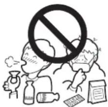
Users of the product
○ The product should not be used by:
• people who are tired
• people who have taken alcohol
• people who are on medication
• people who are pregnant
• people who are in poor physical condition
• people who have not read the operator's manual
children
Keep in mind that the operator or user is responsible for accidents or hazards occurring to other people or their property.
Failure to observe these instructions could lead to an accident.
The ignition system of this product generates electromagnetic fields during operation. Magnetic fields can cause pacemaker interference or pacemaker failure. To reduce health risks, we recommend that pacemaker users consult their physician and the pacemaker manufacturer before operating this product.
text_image
Illustration showing a prohibition symbol over food waste, with people and items like bottles, documents, and a glass nearby.
WARNING
Vibration and cold
It is believed that a condition called Raynaud's Phenomenon which affects the fingers of certain individuals may be brought about by exposure to vibration and cold. Exposure to vibration and cold may cause tingling and burning, followed by loss of colour and numbness in the fingers. The following precautions are strongly recommended because the minimum exposure which might trigger the ailment is unknown.
- Keep your body warm, especially the head and neck, feet and ankles, and hands and wrists.
- Maintain good blood circulation by performing vigorous arm exercises during frequent work breaks, and also by not smoking.
- Limit the number of hours of operation. Try to fill each day with jobs where operating the trimmer or other handheld power equipment is not required.
If you experience discomfort redness and swelling of the fingers, followed by whitening and loss of feeling, consult your physician before exposing yourself further to cold and vibration.
Failure to observe these instructions could result in damage to your health.
Repetitive stress injuries
It is believed that over-using the muscles and tendons of the fingers, hands, arms and shoulders may cause soreness, swelling, numbness, weakness and extreme pain to the areas just mentioned. Certain repetitive hand activities may put you at a high risk for developing a repetitive stress injury (RSI). To reduce the risk of RSI, do the following:
- Avoid using your wrist in a bent, extended or twisted position.
Take periodic breaks to minimize repetition and rest your hands. Reduce the speed and force in which you do the repetitive movement.
Do exercises to strengthen hand and arm muscles. - See a doctor if you feel tingling, numbness or pain in your fingers, hands, wrists or arms. The sooner RSI is diagnosed, the more likely permanent nerve and muscle damage can be prevented.
Failure to observe these instructions could result in damage to your health.
Proper training
○ Do not permit operation without proper training and protective equipment.
○ Be thoroughly familiar with the controls and proper use of unit.
○ Know how to stop the unit and shut off the engine.
○ Know how to unhook a harnessed unit quickly.
○ Never allow anyone to use the unit without proper instruction.
Failure to observe these instructions could result in damage to your health.
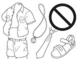
Wear proper clothing.
- Secure hair so it is above shoulder length.
Do not wear ties, jewellery, or loose, dangling clothing which could be caught in the unit.
○ Do not wear open toed footwear, or go bare-foot or barelegged.
Failure to observe these precautions could result in damage to your sight or hearing, or lead to a serious injury.
natural_image
Illustration of clothing items including a shirt, shorts, tie, sandal, and no stop sign (no text or symbols)Wear protective gear
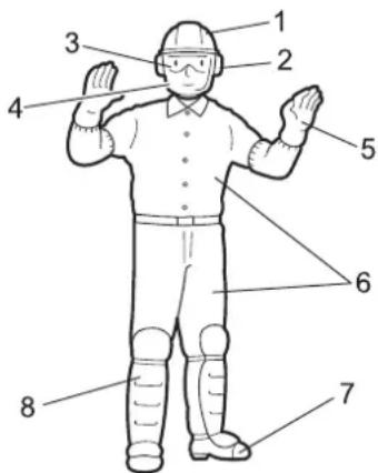
○ Always wear the following protective gear when working with the trimmer.
- Head protection (helmet): Protects the head
- Ear muffs or ear plugs: Protect the hearing
- Safety goggles: Protect the eyes
- Face shield: Protects the face
- Safety gloves: Protect the hands from cold and vibration
- Work clothes that fit (long sleeves, long trousers): Protect the body
- Heavy duty, non-slip protective boots (with toecaps) or non-slip work shoes (with toecaps): Protect the feet
- Shin guards: Protect the legs
Failure to observe these precautions could result in damage to your sight or hearing, or lead to a serious injury.
○ When necessary, please use the protective gear below.
♦ Dust mask: Protects the breathing apparatus
- Bee net: To deal with attacks by bees
text_image
Labeled diagram of a person wearing a helmet and standing with multiple arms and legs numbered 1 to 8.WARNING
Environment of use and operation
Do not use the product:
• under poor weather conditions.
- on steep slopes or in places which give no secure foothold and are thus slippery.
- at night or in dark places with poor visibility.
○ When using the product on a gentle slope, work in a level, contour-like motion.
A serious injury could result if you fall or slip, or fail to operate the product correctly.
For your own health and your safe and comfortable work, operate the machine within the air temperature range of -5^ to 40^ .
Failure to observe these instructions could result in damage to your health.
Being prepared in case of an injury
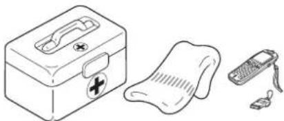
○ In the unlikely event of an accident or injury, please ensure that you are prepared.
- First aid kit
- Towels and wipes (to stop any bleeding)
• Whistle or mobile phone (for calling outside help)
If you are unable to perform first aid or call for outside help, the injury could worsen.
natural_image
Illustration of a first aid kit, medical sphygmoman, and mobile phone (no text or symbols)Put safety first in the case of fire or smoke
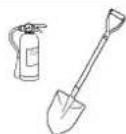
○ If fire comes from the engine or smoke appears from any area other than the exhaust vent, first distance yourself from the product to ensure your physical safety.
Use a shovel to throw sand or other such material on the fire to prevent it from spreading, or put it out with a fire extinguisher.
A panicked reaction could result in the fire and other damage becoming more extensive.
Warning notices

DANGER WARNING AUCTION
This symbol accompanied by the word "DANGER" calls attentions to an act or a condition which will lead to serious personal injury or death of operators and bystanders.
This symbol accompanied by the word "WARNING" calls attentions to an act or a condition which can lead to serious personal injury or death of operators and bystanders.

"CAUTION" indicates a potentially hazardous situation which, if not avoided, may result in minor or moderate injury.
Other indicators

Circle and slash symbol means whatever is shown is prohibited.
NOTE IMPORTANT
This enclosed message provides tips for use, care and maintenance of the product.
Framed text featuring the word "IMPORTANT" contains important information about the use, checking, maintenance and storage of the product described in this manual.
Symbols
| Symbol form/shape Symbol description/application | Symbol form/shape Symbol | description/application |
 | Carefully read the operator's manual |  The maximum speed of the cutting attachment shaft in r/min The maximum speed of the cutting attachment shaft in r/min |
 | Wear eyes, ears and head protection | 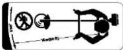 Keep bystanders away 15 m Keep bystanders away 15 m |
For safe use of your product
| Symbol form/shape Symbol | description/application | Symbol form/shape Symbol | description/application |
 | Wear foot protection and gloves |  | Petrol and oil mixture |
 | Emergency stop |  | Choke Control "Cold Start" Position (Choke Closed) |
 | Warning! Thrown objects! | 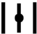 | Choke Control "Run" Position (Choke Open) |
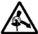 | Warning, side thrust |  | Carburettor adjustment - Idle speed |
 | Usage without shield not permitted | 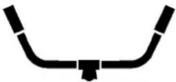 | U-handle |
 | Usage of metal blades not permitted |  | Loop handle |
 | Usage of nylon line cutting head not permitted |  | Beware of high-temperature areas |
 | Do not use the product in plac-es with poor ventilation | 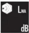 | Guaranteed sound power lev-el |
 | Beware of fire Engine start |  | |
 | Beware of electric shocks |  | Purge bulb (Primer) |
Safety decal(s)
The safety decal shown below has been attached to the products described in this manual. Ensure that you understand what the decal means before using your product.
If the decal becomes unreadable due to wear and tear or damage, or peels off and is lost, please purchase a replacement decal from your dealer and attach it in the location shown in the illustrations below. Ensure that the decal is readable at all times.
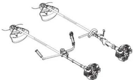
(1. Part number 890617-43130)

text_image
Warning symbols and safety icons including warning, hazard, gear, hand gesture, safety measures, and electrical hazard signs
text_image
Technical diagram of automotive suspension system components with labeled parts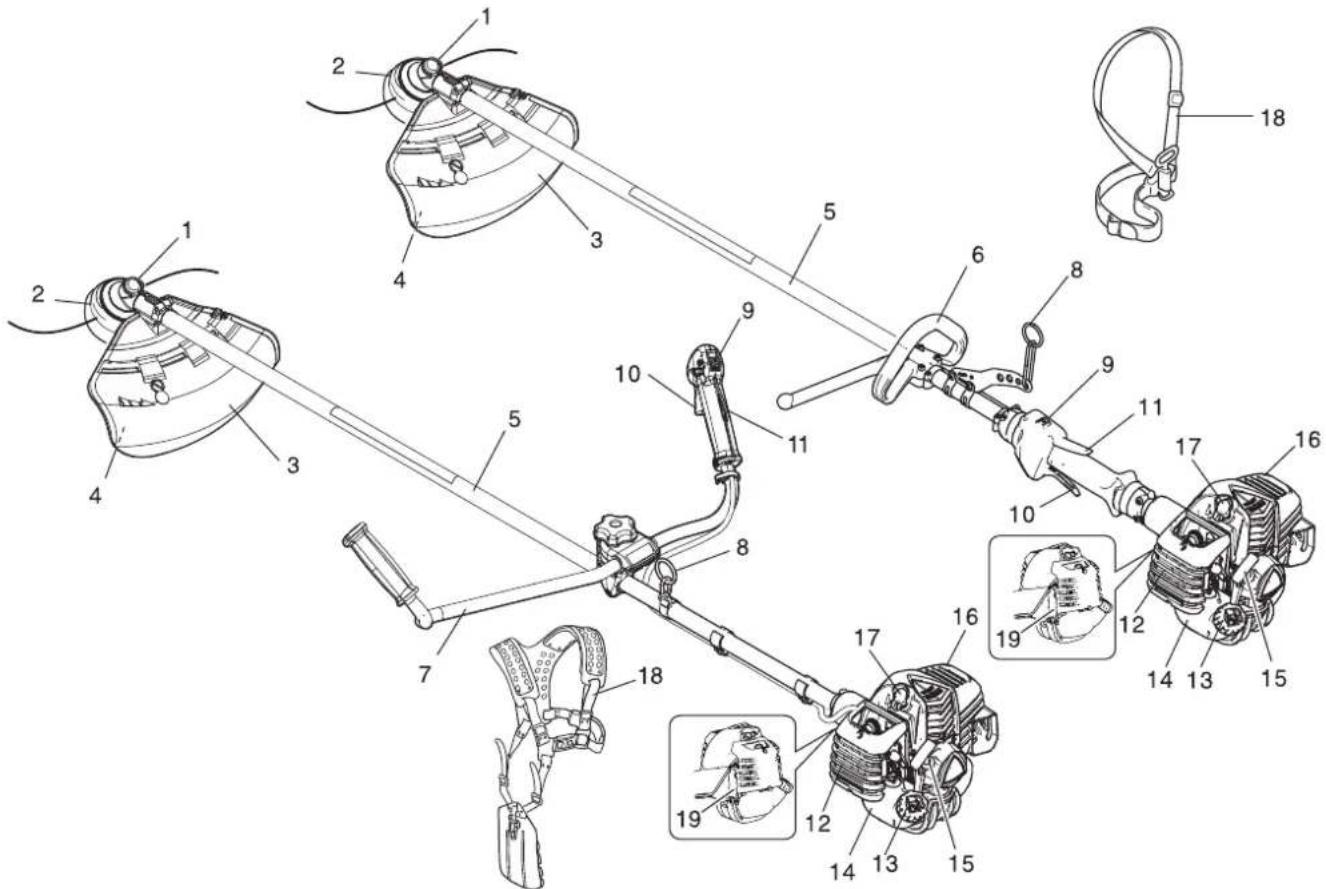
text_image
Technical diagram of a mechanical linkage system with numbered components and close-ups of internal parts.- Angle transmission Having two gears to change the angle of rotating axis.
- Cutting attachment Nylon line cutting head for cutting grass and weed.
- Shield Device to protect the operator from accidental contact with the cutting head and thrown objects.
- Cut off knife Cut nylon line to adjust line length to proper swath.
- Shaft tube Part of the unit that provides a casing for power transmission shaft.
- Loop-handle Light weight, suitable for nylon line trim-mer.
- U-handle Having the configuration of a bicycle handle bar to reduce working effort compared to a loop-handle.
-
Suspension point Device on which the harness can be hooked.
-
Ignition switch "Slide switch" mounted on top of the throttle trigger housing, move switch forward to RUN, backward to STOP position.
- Throttle trigger Activated by the operator's finger for controlling the engine speed.
- Throttle trigger lockout Locks throttle trigger in the idling position until you have a proper grip with your right hand around the handle.
- Air cleaner cover Covers air filter.
- Fuel tank cap For closing the fuel tank.
- Fuel tank Contains fuel and fuel filter.
- Starter handle Pull handle to start the engine.
- Silencer cover Cover the silencer not to make operator touch the hot surface of silencer.
- Spark plug
- Shoulder harness An adjustable strap to suspend unit.
- Type and serial number
Packing list
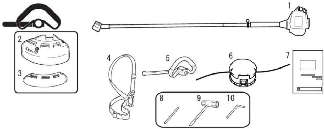
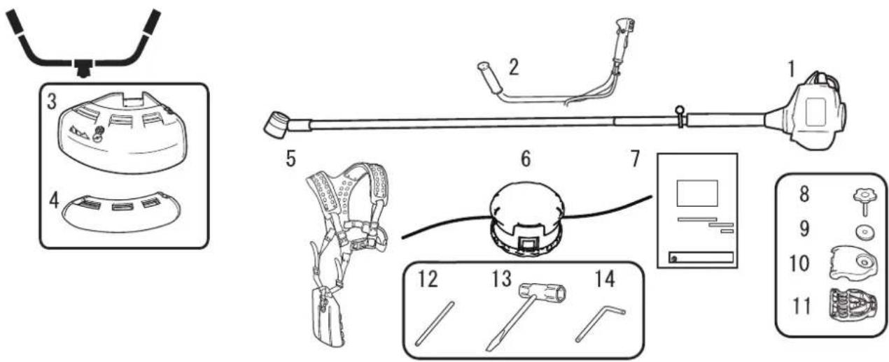
- The following parts are packed separately in the packing box.
When you have unpacked the box, please check the parts that it contains. - Contact your dealer if anything is missing or broken.
text_image
Technical diagram showing exploded view of medical or dental equipment with numbered components and labeled parts- Engine and shaft tube
- Shield (for nylon line cutting head)
- Shield (for metal blade)
- Shoulder harness
-
Loop handle
-
Nylon line cutting head
- Operator's manual
- Locking tool
- Socket wrench
- L-wrench
text_image
Technical diagram showing exploded view and labeled parts of a medical device with numbered components- Engine and shaft tube
- U-handle
- Shield (for nylon line cutting head)
- Shield (for metal blade)
- Shoulder harness
- Nylon line cutting head
-
Operator's manual
-
Handle assembling bolt
- Washer
- Handle assembling bracket (upper)
- Handle assembling bracket (lower)
- Locking tool
- Socket wrench
- L-wrench
Assembly

WARNING
Read the operator's manual carefully to ensure that you assemble the product correctly. Using a product that has been incorrectly assembled could lead to an accident or serious injury.

Loop handle version Loop handle assembly

text_image
A B C D E FAssemble loop handle (A) and bracket (C) to drive shaft assembly. Position handle in comfortable operating position and tighten Bolts (B).
E: Arrow F: To engine

CAUTION
○ Install the handle so that it does not hide any of the safety decals.
U-handle version U-handle assembly
text_image
2:1 B A C E F D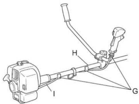
text_image
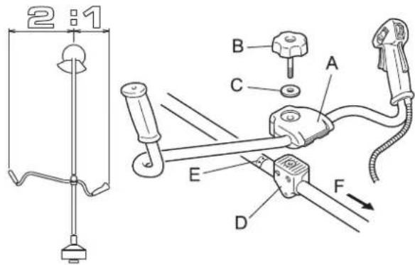
I H G- Install handle assembling bracket (upper) (A) in handle assembling bracket (lower) (D) and fix handle by tightening handle assembling bolt (8 mm) (B) lightly.
- Adjust inclination of handle to adequate position (easy to operate) and tighten firmly handle assembling bolt.
C: Washer
E: Arrow
F: To engine

CAUTION
○ Install the handle so that it does not hide any of the safety decals.
- To eliminate loosening of throttle wire (I), fix it to shaft tube (H) (2 places) and to right hand U-handle (1 place) with wire fixing clips (G).
text_image
1 - 2 mm K L J
CAUTION
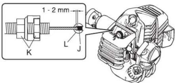
○ After assembly, adjust the play of wire end (J) on carburettor (L) side to 1 mm - 2 mm.
K: Nuts
Installation of shield
text_image
B AInstalling nylon line cutting head
text_image
Technical diagram of a mechanical assembly with labeled parts A through E, including a detailed inset view of a circular component.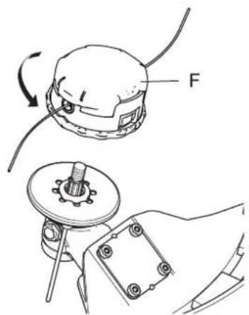
text_image
Technical diagram showing mechanical assembly with labeled component 'F' and directional arrow indicating rotation or movement-
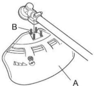
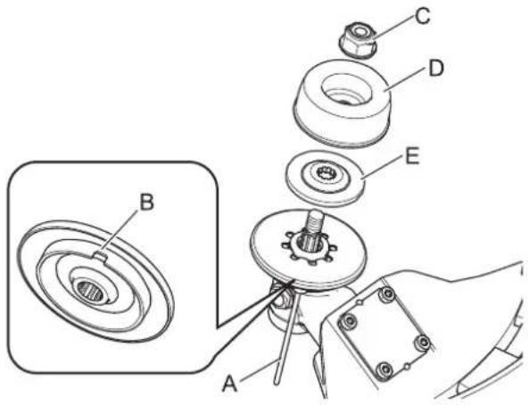
Fit shield (A) to mounting portion of angle transmission and tighten 4 bolts (B).
-
Insert locking tool (A) into a hole located on the right side of angle transmission while forcing retainer spring to the left side.
- Insert locking tool further into blade retainer fixing slot (B) to fix output shaft.
- Using the socket wrench, remove the nut (C), cup (D), and lower blade retainer (E).
*Nut, cup, and lower blade retainer are not used with a nylon line cutting head.

CAUTION
☐ Fix output shaft securely using locking tool in order to prevent it form rotating when nylon cutting head is mounted.
- Thread nylon line cutting head (F) onto shaft (anticlockwise) until it is tight.
- Remove locking tool.
Adjusting the balance
Adjusting the shoulder harness

WARNING
This product is designed to fit a wide variety of body sizes, but may not be adjustable for extremely tall persons. Do not use the unit if your feet can reach the cutting attachment when the unit is attached to the harness.
IMPORTANT
A person's size can affect the balancing adjustment. Also the balancing procedure may not work with some units on some persons. If the shoulder harness does not fit you or cannot be adjusted well, please ask your dealer for assistance.
text_image
A BBalance tool for a level plane of cutting head rotation
natural_image
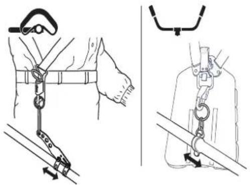
Illustration of two safety harnesses with rope and chain links, showing hand positioning and lifting mechanism (no text or symbols)- The accompanying shoulder harness is suitable for people of standard adult physique, who are 150 cm - 195 cm in height and 60 cm - 140 cm in waist size.
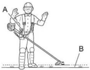
Use a shoulder harness when provided or when recommended in this manual. Adjust both harness and the suspension point (A) on the unit so the unit hangs with the cutting attachment a few centimetres above ground level (B). - The cutting attachment and shield should be level in all directions. Harness the unit on the right side as shown.
- Slide suspension point up and down the tube to find the right balance. Rotate the clamp to level the cutting attachment and shield. Lock in position. If the suspension point is a free-spinning type, the unit may tend to roll over sideways, however, you should still level the attachment and shield on the front-to-rear axis.
- Balancing and levelling, as above, may require relocation of the clamp and readjustment of the harness straps. Also, each type of cutting attachment and shield mounted on the unit may require balancing.
Preparing the fuel

DANGER
○ Do not fuel up while the engine is hot or in operation.
○ Do not smoke or hold a flame near when refuelling.
If you do so, the fuel could ignite and cause fire, leading to burns.


WARNING
Do not fill fuel tanks indoors. Always fill fuel tanks outdoors over bare ground. Do not refuel the product on the loading platform of a truck, or in other such places.
- Fuel tanks/cans may be under pressure. Always loosen fuel caps slowly allowing pressure to equalize. Otherwise, fuel may get spewed.
- Mop up any fuel that overflows or spills out due to overfilling.
Fuel spills can cause fire and burns when ignited.
○ After refuelling, always check that there are no leaks or discharges of fuel from the fuel pipe, fuel system grommets, or around the fuel tank cap. If you do find fuel leaks or discharges, stop using the product immediately and contact your dealer to have it repaired.
Any fuel leaks could cause fire.
- Keep the refuelling tank in a shaded area away from fire.
○ Use an approved fuel container.
IMPORTANT
Fuel is a mixture of regular grade petrol and an air-cooled 2-stroke engine oil. Minimum 89 Octane unleaded petrol is recommended. Do not use fuel containing methyl alcohol or more than 10 % of ethyl alcohol.
○ Stored fuel ages. Do not mix more fuel than you expect to use in thirty (30) days.
Fuel

Fuel supply
text_image
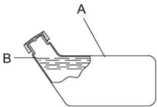
A B- Recommended mixture ratio; 50: 1 (2%) for ISO-L-EGD Standard (ISO/CD 13738), JASO FC, FD grade and shindaiwa recommended oil.
-
Never use two-stroke oil intended for water-cooled engines, motor-cycle engines.
• Do not mix directly in engine fuel tank. -
Do not add so much fuel that it reaches the mouth of the fuel tank (A). Keep the fuel within the prescribed level (up to the shoulder level (B) of the fuel tank).
- Tighten the fuel tank cap securely after refuelling.
Starting the engine

WARNING
Be particularly careful to observe the following precautions when starting the engine:
○ Move at least 3m from the place where you refuelled.
○ Place the product in a flat, well ventilated place.
○ Check that there are no fuel leaks.
○ Inspect metal blades for cracks.
○ Check that none of the nuts and bolts are loose.
○ Leave plenty of space around the product and do not allow people or animals near it.
○ Start the engine with the throttle trigger in the idle speed position.
○ Hold the product firmly to the ground when starting the engine.
Failure to observe the precautions could cause an accident or injury, or even lead to a fatality.
☐ Check that there are no abnormal vibrations or sounds once the engine starts. Do not use the product if there are abnormal vibrations or sounds. Contact your dealer to have it repaired.
Accidents involving parts that fall or shatter off can cause wounds or serious injury.
The exhaust fumes from the engine contain toxic gases. Do not operate the product indoors or in other ill ventilated places.
The exhaust fumes could cause poisoning.

Do not touch silencer, spark plug, angle transmission, and other high temperature components while the product is running or for some time after it stops.
You could burn yourself if you touch a high temperature component.

○ Do not touch spark plug, spark plug wire, and other high voltage components while the product is running.
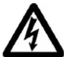
You could receive an electric shock if you touch a high voltage component while the product is running.
○ If the cutting attachment rotates even though the throttle trigger is in the idle speed position when the engine is started, adjust the carburettor before using the product.
Failure to observe the precautions could cause an accident or injury, or even lead to a fatality.
When starting engine using throttle latch, cutting attachment rotates. After engine starts, pull throttle trigger slightly to release throttle latch immediately. Never use throttle latch for operation.
The rotating blade can cause injury.
NOTE
○ Pull out the starter grip gently at first, and then more rapidly. Do not pull the starter rope out to more than 2/3 of its length.
- Do not let go of the starter grip as it returns.
Starting a cold engine
text_image
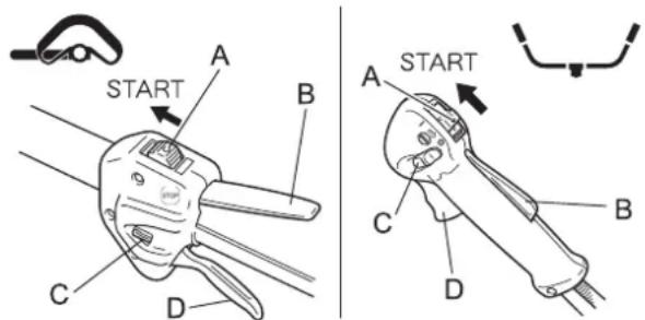
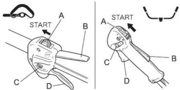
START A B C D A START C B D(Connect the spark plug cap if the product has been in storage for a long period of time.)
- Remove the blade cover.
- Placing the product on level ground, check to ensure that the cutting attachment does not come into contact with the surface of the ground or any other impediment using a beam or other such implement.
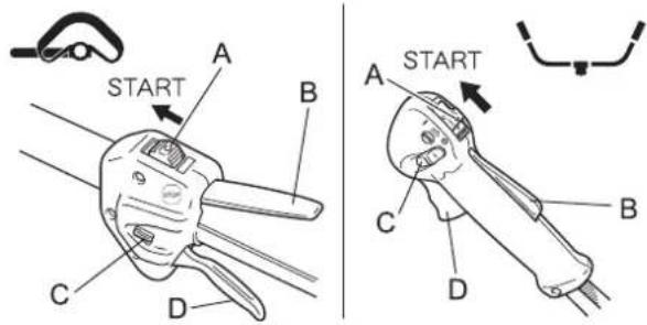
- Move the ignition switch (A) to the Start position.
- Make sure that the throttle trigger (D) is at the idle speed position.
text_image
HE F IG H I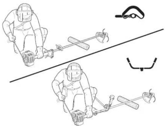
natural_image
Illustration of two workers in protective gear using a tool, with no visible text or symbolsStarting a warm engine
text_image
A START B C D A START C B DStopping the engine
text_image
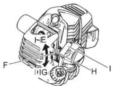
A STOP B A STOP B- Move the choke lever (F) to the "Cold Start" (E) position.
- Alternately press and release the purge bulb (H) until the fuel is sucked up into it.
- Checking that the area around you is safe, hold the position closest to the engine firmly as shown in the illustration, pulling several times on the starter grip (I).
- If you hear an explosion-like sound and the engine stops immediately, move the choke lever to the "Run" (G) position and continue pulling on the starter grip to start the engine.
- If the engine does not stop, return the choke lever gently to the "Run" position.
- Leave the engine to warm up at idle speed for a while.
* When engine is hard to start, use throttle latch (C). (Pull throttle trigger fully and lower throttle latch while pressing throttle trigger lockout (B) and release throttle trigger to activate throttle latch. After engine starts, pull throttle trigger slightly to release throttle latch immediately.)
- Move the ignition switch (A) to the Start position.
- Make sure that the throttle trigger (D) is at the idle speed position.
- Check that the choke lever is in the "Run" position.
- If no fuel is visible in the purge bulb, alternately press and release the purge bulb until the fuel is sucked up into it.
-
Checking that the area around you is safe, hold the position closest to the engine firmly, and pull on the starter grip to start the engine.
-
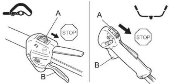
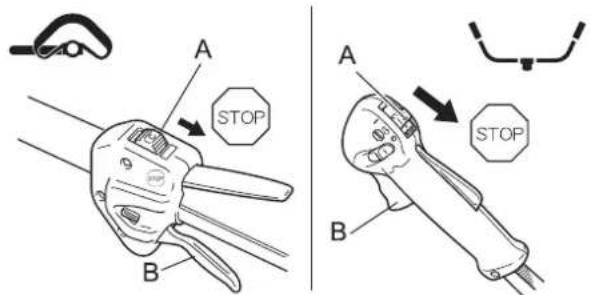
Move the throttle trigger (B) to the idle speed position and set the engine to idling (i.e. low speed).
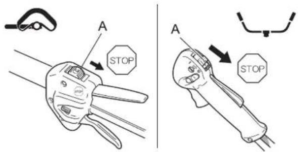
- Move the ignition switch (A) to the Stop position.
- In the event of an emergency, stop the engine immediately using the ignition switch.
- If the engine fails to stop, move the choke lever to the "Cold Start" position. The engine will stall and come to a halt (an emergency stop).
* If the engine fails to stop when the ignition switch is used, have the ignition switch checked and repaired by your dealer before you use the product again. - Always disconnect the spark plug wire from the spark plug to ensure the engine cannot be started before you work on the unit or leave it unattended.

DANGER
○ Always stop the engine when a cutting attachment jam occurs.
Severe injury can occur if a jam is removed and the cutting attachment suddenly starts.
○ Do not operate the product without the shield in place.
Any objects that ricochet off the cutting attachment could cause an accident or serious injury.
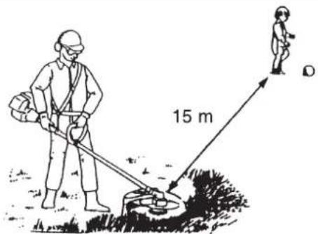
The area within a 15 m radius of the product is a danger zone. Be careful to observe the following precautions while working with the product.
- Do not allow children and other people or pets to enter the danger zone.
- If another person enters the danger zone, turn off the engine to stop the cutting attachment from rotating.
When approaching the operator, signal to him by, for example, throwing twigs from outside the danger zone, and then check that engine has been switched off and the cutting attachment has stopped turning. - If more than one person is working with the product, identify the way in which you will signal to each other and work at least 15 m apart.
text_image
15 mAny objects that ricochet off the cutting attachment, and any contact with the cutting attachment, could cause blindness or a fatal accident.

WARNING
Before starting work, check the area where you will be working and remove any small stones and empty cans likely to ricochet off the cutting attachment, as well as any pieces of string or wire that might become twisted around the cutting attachment.
An accident or serious injury can occur if foreign objects ricochet off the cutting attachment or wire and other materials twisted round the product spring off it.
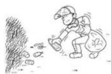
○ In the following situations, turn off the engine immediately and ensure that the cutting attachments have stopped before checking each area of the product. Replace any damaged parts.
- If the cutting attachment hits a rock, tree, post, or other such obstruction while you work.
If the product suddenly starts to vibrate abnormally.
Continuing to use parts when they are damaged could lead to an accident or serious injury.
Do not hold the cutting attachment up while you work. You must not work with the cutting attachments raised above knee level.
Raising the cutting attachment above knee level brings the plane of rotation closer to the face, and any objects that fly off the cutting attachments could cause an accident or serious injury.
Transport of the product
When transporting in the situations described below, turn off the engine and ensure that the trimmer blade has stopped rotating, then fit the trimmer blade cover and position the silencer away from yourself.
- Moving to the place where you are working.
- Moving to another area while you are working.
• Leaving the place where you have been working.
Failure to observe these precautions could cause burns or serious injury.
When transporting the product by car, empty the fuel tank, fit the blade cover, and secure the product firmly in place to prevent it from moving around.
Travelling by car with fuel in the fuel tank could lead to a fire.
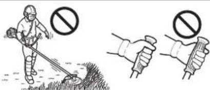
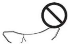
Never attempt to operate the product with one hand.
- Ensure that you hook your thumbs around the grips, wrapping them in your thumb and remaining fingers.
text_image
Illustration showing a person sweeping with a shovel and a prohibition symbol, alongside two hand gestures.Using shoulder harness
text_image
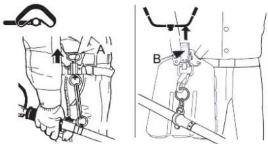
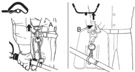
Technical diagram showing two mechanical assembly steps labeled A and B, with arrows indicating motion direction.Always mount the trimmer correctly using the shoulder harness.
- Buckle waist belt (Loop handle version). Belt should be snug.
- Attach product to harness.
- Loop handle version
Place shoulder harness over left shoulder and adjust straps so the quick release pin rests just below the waist.
♦ U-handle version
Place shoulder harness over both shoulders and adjust straps so the connecting point latches as shown.
- Check for correct adjustment by moving cutting attachment along ground.
- Re-adjust position of suspension point if necessary.
- The shoulder harness is fitted with an emergency release function.
- Loop handle version: In the event of a fire or other emergency, pull the quick release pin (A) up to release the product from your body.
- U-handle version: In the event of a fire or other emergency, pull the emergency tab (B) up to release the product from your body.
Basic trimming operation with nylon line cutting head
WARNING
- Serious injury may result from the improper use of cutting attachment. Read and comply with all safety instructions listed in this manual.
○ Use only cutting attachments recommended by YAMABIKO Corporation.
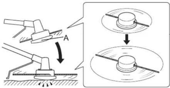
○ Excessive nylon line beyond cut off knife could fly off when the nylon line cutting head starts rotating after adjustment of nylon line length.
Failure to do so could lead to an accident or serious injury.
Adjusting nylon line
text_image
Technical diagram illustrating a mechanical assembly process with labeled components and directional arrowsTrimming
text_image
Technical diagram of a mechanical device with numbered components and dimension annotations- Cut off knife on the shield adjusts cutting swath automatically by cutting nylon lines evenly when attachment starts rotating.
- When operating with less than maximum cutting swath, cut two nylon lines in equal lengths.
-
To advance trimmer line, tap the nylon line cutting head (A) against the ground while the head is turning at normal operating speed.
-
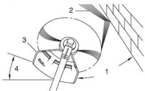
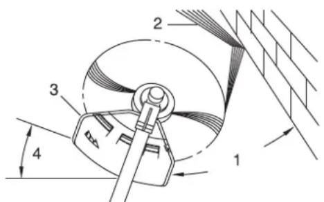
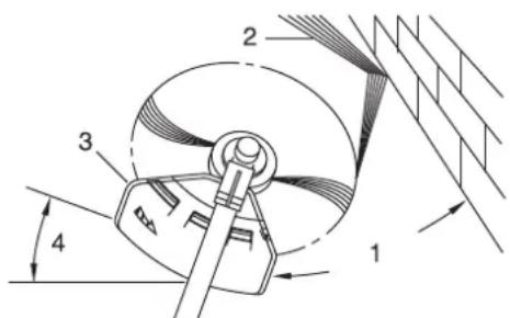
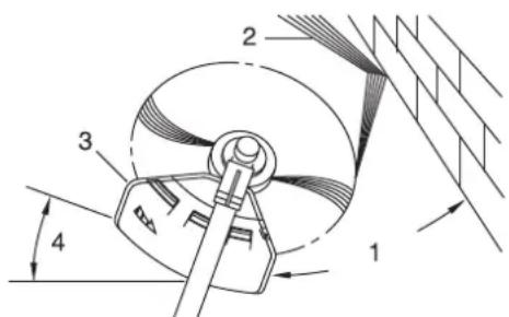
This is feeding the trimmer carefully into the material you wish to cut. Tilt the head slightly to direct the debris away from you. If cutting up to a barrier such as a fence, wall or tree, approach from an angle where any debris ricocheting off the barrier will fly away from you.
- Move the nylon line cutting head slowly until the grass is cut right up to the barrier, but do not jam (overfeed) the line into the barrier. If trimming up wire mesh or chain link fencing, be careful to feed only up to the wire. If you go too far, the line will snap off around the wire.
- Trimming can be done to cut through weed stems one at a time. Place the nylon line cutting head near the bottom of the weed never high up, which could cause the weed to chatter and catch the line. Rather than cut the weed right through, just use the very end of the line to wear through the stem slowly.
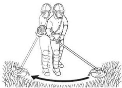
Scything
natural_image
Illustration of two workers in protective gear using a tool to measure a wetland or excavation site (no text or symbols present)Scalping and edging
natural_image
Two illustrations of a person in protective gear using tools to lift a tree, labeled A and B (no text or symbols on the figures themselves)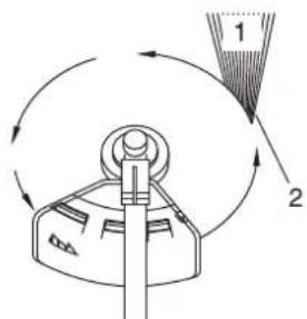
text_image
Diagram showing a mechanical device with labeled parts and directional arrows indicating motion or rotation.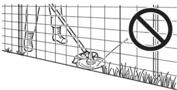
text_image
Diagram showing a fence with grass, a person holding a device, and a prohibition symbol in the background.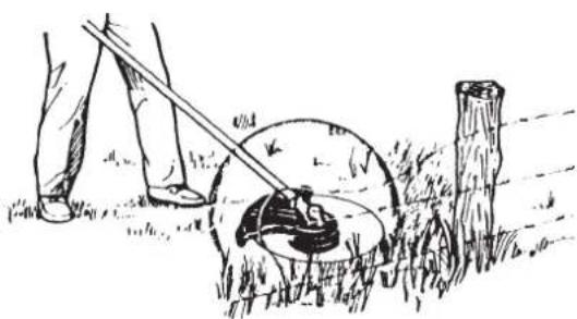
natural_image
Illustration of a person using a grassy net to lift a pole, with no text or symbols present.- Angle to wall
- Debris
- Knife side raised
- Angle to ground
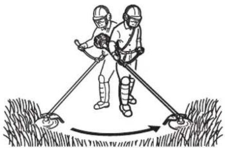
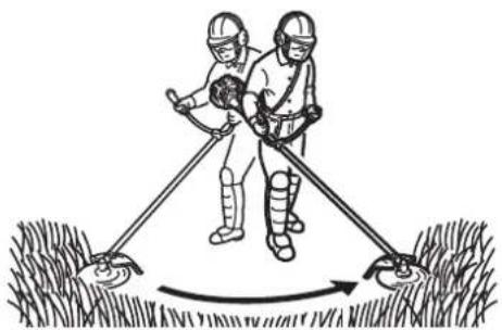
- This is the cutting or mowing of large grassy areas by sweeping or swinging the trimmer in a level arc. Use a smooth, easy motion. Do not try to hack or chop down the grass. Tilt the nylon line cutting head to direct the debris away from you on the scything stroke. Then return without cutting grass for another stroke. If you are well protected and do not care whether some debris is thrown in your direction, you may scythe in both directions.
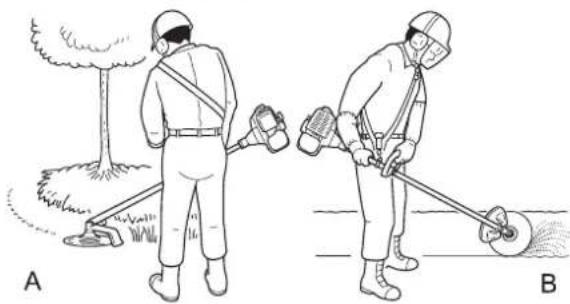
Both of these are done with the nylon line cutting head tilted at a steep angle. Scalping (A) is removing top growth, leaving the earth bare. Edging (B) is trimming the grass back where it has spread over a pavement or driveway. During both edging and scalping, hold the unit at a steep angle in a position where the debris, and any dislodged dirt and stone, will not come back towards you even if it ricochets off the hard surface.
Although the pictures show how to edge and scalp, every operator must find for himself the angles which suit his body size and cutting situation.
- For nearly all cutting, it is good to tilt the nylon line cutting head so that contact is made on the part of line circle where the line is moving away from you and the shield (See appropriate picture). This results in the debris being thrown away from you.
- Tilting the head to the wrong side will shoot the debris toward you. If the nylon line cutting head is held flat to the ground so that cutting occurs on the whole line circle, debris will be thrown at you, drag will slow the engine, and you will use up a lot of line.
- Nylon line cutting head rotates anticlockwise. The knife will be on the left side of the shield.
-
Debris
-
Cut on this side
-
Do not push the line into tough weeds, trees, or wire fences.
- Pushing the line into chicken wire, chain link fencing or thick brush can result in snapped-off line ends being hurled back at the operator. The proper way is to cut right up to a barrier, such as any of those mentioned, but never run the line into or through the obstruction. Do not cut closely to obstruction or barrier.
- Avoid nylon line contact with broken wire fencing. Pieces of wire broken off by the trimmer can be hurled at high speeds.
Basic trimming operation with metal blade

WARNING
Please observe the following instructions when trimming.
- Check to ensure that the trimmer blade has been tightened securely in place.
♦ Replace the shield if it is damaged or cracked. - Replace the trimmer blade nut when it becomes worn.
Do not cut into the ground with the blade. - Do not operate with a dull, bent, fractured or discoloured blade and worn or damaged nut.
Do not run engine at full throttle without a load.
Failure to do so could lead to an accident or serious injury.
Use only cutting attachments recommended by YAMABIKO Corporation. YAMABIKO Corporation will not be responsible for the failure of cutting devices, attachments or accessories which have not been tested and approved by YAMABIKO Corporation for use with this unit.
The type of blade used must be matched to the type and size of material cut. An improper or dull blade can cause serious personal injury. Blades must be sharp. Dull blades increase the chance of kick-out and injury to yourself and bystanders.
- Plastic/Nylon Grass/Weed Blades may be used where ever the nylon line head is used. Do not use this blade for heavy weeds or brush.
The 3 cutter blade is designed especially to cut weeds and grass. To avoid injury due to kickback or blade fracture, do not use the 3 cutter blade to cut brush or trees. - 8 Tooth Weed/Grass Blade is designed for grass, garden debris and thick weeds. Do not use this blade for brush or heavy woody growth, 19 mm diameter or larger.
• 22 Tooth Clearing Blade is designed for dense thickets and saplings up to 64 mm diameter. - 80 Tooth Brush Blade is designed for cutting brush and woody growth up to 13 mm diameter.
Damaged or shattered blades can cause accidents and serious injury.
Kickback
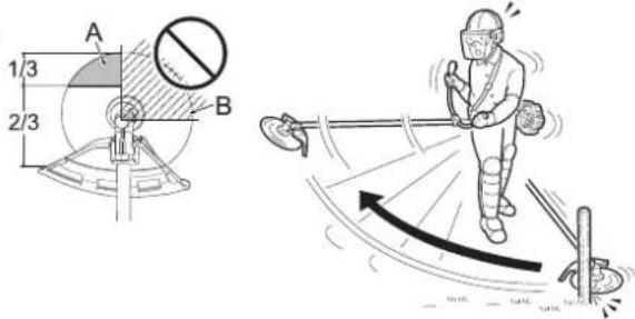
The phenomenon that occurs if the trimmer blade comes into contact with a tree, post, rock or other hard object while rotating at high speed and reacts by recoiling powerfully and instantaneously is known as kickback.
○ Causing kickback can result in a loss of control over the product and is highly dangerous.
○ In particular, if the front-right quadrant of the trimmer blade (B) strikes a shrub or other such object, the trimmer blade will cause the product to recoil sharply backwards to the right.
To prevent kickback, do not trim from left to right. Be careful to ensure that the trimmer blade does not strike any hard objects.
When trimming, ensure that the object you are cutting meets the portion of the blade 1/3 in from the front edge on the left-hand side (A).
Failure to do so could cause an injury or fatal accident.
text_image
A 1/3 2/3 BScything weeds
natural_image
Illustration of two workers using a tool to measure a slope, with no text or symbols present.- This is cutting by swinging the cutting attachment in a level arc. It can quickly clear areas of field grass and weeds. Scything should not be used to cut large, tough weeds or woody growths.
- If a sapling or shrub binds the cutting attachment, do not use the cutting attachment as a lever to free the bind, because this will cause cutting attachment failure.
- Instead, shut off the engine and push the sapling or shrub to free the blades.
WARNING
Observe the following precautions when checking and maintaining your product after use:
Turn the engine off and do not attempt to check or maintain the product until the engine has cooled. You could burn yourself.
○ Remove the spark plug cap before performing checks and maintenance. An accident could occur if the product starts unexpectedly.
IMPORTANT
○ Checking and maintenance requires specialist knowledge. If you are unable to check and maintain the product or deal with a fault yourself, consult your dealer. Do not attempt to dismantle the product.
For spare parts and consumables, please use only genuine parts and designated products and components. Using parts from other manufacturers or non-designated components may result in a malfunction.
Servicing guidelines
| Area Maintenance Page Before use Monthly | |||
| Air filter Clean/Replace 21 • | |||
| Fuel filter Inspect/Clean/Replace 21 • | |||
| Spark plug Inspect/Clean/Adjust/Replace 23 • | |||
| Carburettor | Adjust/Replace and adjust | 21 | |
| Cooling system | Inspect/Clean | 22 • | |
| Silencer | Inspect/Tighten | 22 • | |
| Silencer | Clean | 22 | |
| Angle transmission | Grease | 23 | |
| Starter | Inspect | - | • |
| Cut off knife | Inspect/Clean | - | • |
| Fuel system | Inspect | 21 • | |
| Screws, bolts and nuts | Inspect, Tighten/Replace | - | • |
* Or 50 hours, whichever occurs first. ** Or 100 hours, whichever occurs first.
IMPORTANT
○ Time intervals are maximum. Actual use and your experience will determine the frequency of required maintenance.
Maintenance and care
If you have any questions or problems, please contact your dealer.
Cleaning air filter
text_image
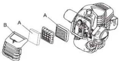
Technical diagram of an automotive electrical connector with labeled parts A and B- Close choke. Loosen air cleaner cover knob and remove air cleaner cover (B).
- Remove air filter (A) (air filter is located inside air cleaner cover).
- Brush dirt from filter or clean with compressed air from carburettor side.
- Reinstall air filter with cover, after installing air filter to cover.
- Tighten air cleaner cover knob.
NOTE
When reinstall air filter, fit it in the frame of the cleaner case.
Replacing fuel filter
text_image
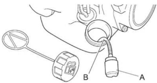
Technical diagram showing a car's internal components with labeled parts A and B, including a connector and cable.- Use a piece of metal wire or the like to pick up fuel filter (A) through fuel tank opening.
- Pull old filter from fuel line (B).
- Install new fuel filter.
NOTE
○ If filter is excessive dirty or no longer fits properly, replace it.
Carburettor adjustment

WARNING
- YOU MAY ADJUST THE IDLE SPEED ONLY by turning the idle speed adjustment screw (T).
During carburettor adjustment, the cutting attachment may move. Pay utmost attention and care to the cutting attachment so as not to get injured by the moving cutter.
When carburettor adjustment is completed, the cutting attachment should not move at idle speed, otherwise serious personal injury may result. - You must NOT carry out any Carburettor adjustment, other than the idle speed. All other adjustments MUST be performed by an authorized service dealer, or serious personal injury may result due to malfunction of the engine.

CAUTION
○ When there is trouble with the carburettor, contact an authorized service dealer.

natural_image
Technical line drawing of a mechanical engine assembly (no text or symbols visible)Every unit is test run at the factory and the carburettor is fine tuned for maximum performance.
Before adjusting carburettor, clean or replace air filter, start engine and run several minutes to bring it to operating temperature. The engine must return to idle speed whenever the throttle lever is released. Idle speed is adjustable, and must be set low enough to permit the engine clutch to disengage the cutting attachment.
To adjust the carburettor proceed as follow:
- Place the unit on the ground, then start the engine, and then allow it to idle 2-3 minutes until warm.
- If the attachment moves when the engine is at idle, reduce the idle speed by turning the idle adjustment screw(T) counter-clockwise.
- Repeat the process of accelerating to full throttle and return to idle a few times. Check that the cutting attachment stops moving at idle.
- If a tachometer is available, the engine idle speed should be final adjusted to the settings recommended in the Specifications section.
NOTE
When the carburettor cannot be adjusted properly with the idle speed adjustment screw (T), you must contact an authorized service dealer.
Cooling system maintenance
IMPORTANT
To maintain proper engine operating temperature, cooling air must pass freely through the cylinder fin area. This flow of air carries combustion heat away from the engine. Overheating and engine seizure can occur when:
- Air intakes are blocked, preventing cooling air from reaching the cylinder. - Dust and grass build up on the outside of the cylinder. This build-up insulates the engine and prevents the heat from leaving.
Removal of cooling passage blockages or cleaning of cylinder fins is considered "Normal Maintenance". Any resultant failure attributed to lack of maintenance is not warranted.
natural_image
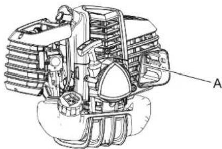
Technical line drawing of a mechanical assembly with labeled component A (no text or symbols beyond label)Air intake
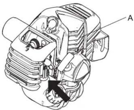
- Remove dust and dirt from between fins (A). - Before each use, remove accumulated debris from bottom engine intake grille located between the fuel tank and starter.
Cleaning silencer
natural_image
Technical line drawing of a mechanical engine assembly (no text or symbols visible)Check fuel system
text_image
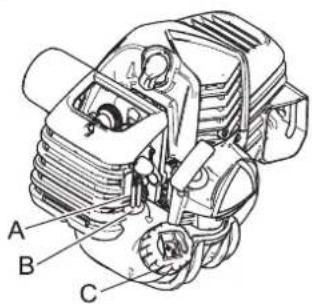
A B C- Carbon deposits in silencer (A) will cause a drop in engine output and overheating. Spark arrestor screen must be checked periodically. Clean deposits from silencer.
IMPORTANT
Do not remove the silencer cover. If necessary, Please consult your dealer.
- Check before every use.
• After refuelling, make sure fuel does not leak or exude from around fuel pipe (A), fuel grommet (B) or fuel tank cap (C). - In case of fuel leakage or exudation, there is a danger of fire. Stop using the machine immediately and request your dealer to inspect or replace.
Check spark plug
text_image
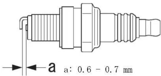
a: 0.6 - 0.7 mmAngle transmission
text_image
Technical diagram of a mechanical device with labeled parts A, B, and CMethod to change shield
text_image
Technical diagram showing a mechanical assembly with labeled parts A, B, C, D, and E, including a circular component and directional arrows indicating process flow.Installing blade (option)
- Check plug gap. Correct gap is 0.6 mm to 0.7 mm.
- Inspect electrode for wear.
- Inspect insulator for oil or other deposits.
- If the spark plug is dirty, clean it. Do not sandblast to clean. Remaining sand will damage engine.
- If the electrodes or terminals are worn, or if there are cracks in the ceramics, replace them with new parts. (see Specifications page 28)
-
Tighten to 10 N·m - 15 N·m (100kgf·cm to 150 kgf·cm).
*The spark test (for checking whether the spark plug is sparking) must be carried out by your dealer. -
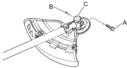
Remove the plug (A) and drain screw (B) from the angle transmission (C).
- Add grease into the transmission until old grease is pushed out. If necessary, use a low pressure pump.
NOTE
○ Use good quality lithium multi grease.
-
Reinstall the drain screw and plug.
-
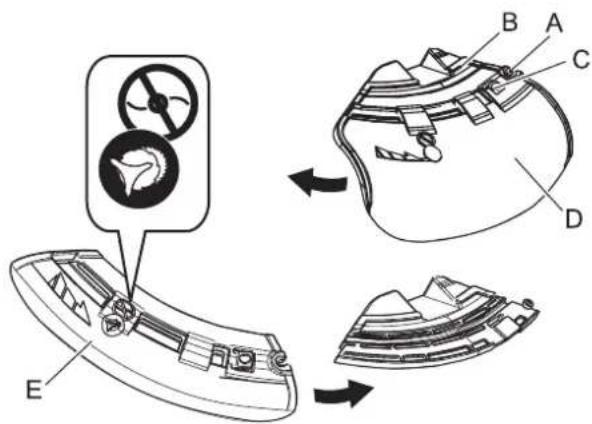
There are two types of shields: namely the one used exclusively for nylon line cutting head and the other one used exclusively for metal blade. When metal blade is used, use the shield for metal blade.
- Fully loosen the bolt (A) on the right side of the bracket (B) to slide the shield. The bolt itself cannot be removed from the bracket.
- Pushing the button (C), slide the shield (D) to the left and remove it.
- Put shield of other type (E) into groove and slide it to the right until it stops. Be sure to tighten the bolt.
WARNING
○ Wear heavy duty gloves when working with the trimmer blade.
When replacing the trimmer blade during a trimming task, ensure that the engine is switched off and that the blades have stopped.
When turning the product over to replace the trimmer blade, ensure that the fuel tank cap is securely in place.
Do not attempt to fit the trimmer blade with one hand or without using the socket spanner. Fit the trimmer blade accurately using the supplied socket spanner and tighten firmly in position.
Do not use any tools other than the provided socket spanner to tighten the blade; a pneumatic or electric tool may tighten the blade more than necessary and cause the nut or the output shaft to break.
○ If worn nut and cup for blade are used, there is a danger of blade getting loose. Replace them with new one. Failure to do so could lead to an injury or serious accident, or cause a fire.
text_image
Technical diagram of a mechanical assembly with labeled parts A through F, including a detailed inset view of the component.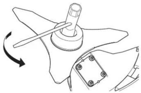
natural_image
Technical line drawing of a mechanical component with a rotating arrow indicating rotation (no text or symbols)Checking the blade
natural_image
Simple line drawing of a curved object with dashed lines indicating alignment or projection (no text or symbols)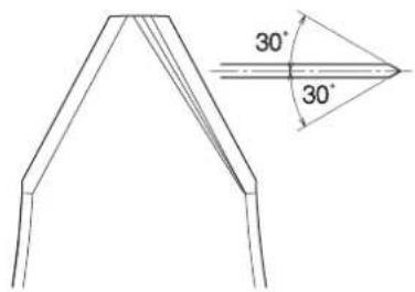
text_image
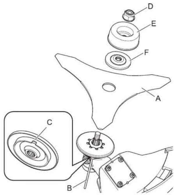
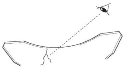
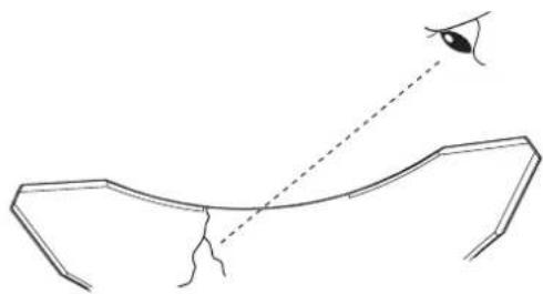
30° 30°- Inspect blades (A) before installation. Check for sharpness. Dull blades increase the risk of blade kickback reactions. Small cracks can develop into fractures resulting in a piece of blade flying off during operation. Discard cracked blades no matter how small the crack.
- Insert locking tool (B) into a hole located on the right side of angle transmission while forcing retainer spring to the left side.
- Insert locking tool further into blade retainer fixing slot (C) to fix output shaft.
- Using the socket wrench, remove the nut (D), cup (E), and lower blade retainer (F).
- Securely tighten the blade, lower blade retainer, cup, and nut by hand.
CAUTION
☐ Fix output shaft securely using locking tool in order to prevent it form rotating when blade is mounted. Otherwise, the blade fastening nut will not be tightened sufficiently.
- Tighten the nut (turn anticlockwise) using a socket wrench. Never fasten while applying your weight. Otherwise the thread of nut could be broken.
- Remove locking tool.
• Use only blade designated for this model by the manufacturer.
- When a crack is noticed on the blade, do not use it but replace with a new one.
- Ensure that the blade is correctly fitted in accordance with the instructions.
- When the cutting blade becomes dull due to wear reverse it for further use.
- When chip or bend occurs on the blade, vibration will increase. Replace with new one.
- When filing the blade file 3 cutting edges evenly using a flat file as shown in the illustration. Otherwise, the balance will be lost and vibration will increase.
Loading nylon line
text_image
Technical diagram showing four steps of a manual tool manipulation or assembly procedure, labeled 2 to 4.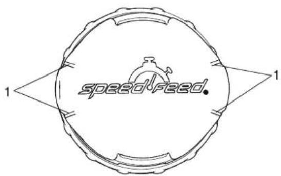
text_image
speedfeed.-
Wear Indicators
-
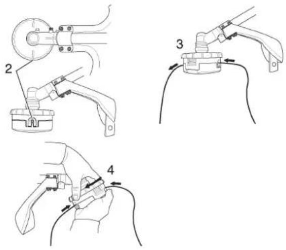
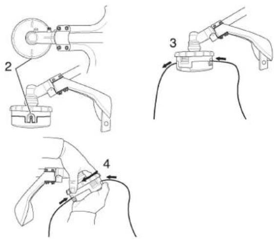
Cut one piece of line to recommended length.
2.4 mm dia. - 6 m - Align arrows on top of knob with openings in eyelets.
- Insert one end of nylon line into an eyelet, and push line equal distance through nylon line cutting head.
- Hold nylon line cutting head while turning knob clockwise to wind line onto spool until about 13 cm of each line remains exposed.
IMPORTANT
When the wear indicators located at the bottom of the nylon line cutting head are worn smooth, replacement of the cover or the entire nylon line cutting head is required.
Troubleshooting table
| IMPORTANT | |||
| ○ For spare parts and consumables, please use only genuine parts and designated products and components.Using parts from other manufacturers or non-designated components may result in a malfunction. | |||
| Problem Diagnosis Cause Solution | |||
| The engine does not start | 1. There is no fuel in the fuel tank2. The stop switch is in the Stop position3. Excess fuel suction4. Electrical fault5. Carburettor malfunction or internal sticking6. Internal engine malfunction | 1. Fuel supply2. Move to the Start position3. Start the engine after servicing4. Consult your dealer5. Consult your dealer6. Consult your dealer | |
| Engine is difficult to start, fluctuating rotation | Fuel is entering the overflow pipe | 1. Fuel degradation2. Carburettor problem | 1. Replace with new fuel2. Consult your dealer |
| No fuel is entering the overflow pipe | 1. Fuel filter is clogged2. Fuel system is clogged3. Internal carburettor parts sticking | 1. Clean or replace2. Consult your dealer3. Consult your dealer | |
| The spark plug is dirty or damp | 1. Fuel degradation2. Incorrect electrode gap3. Carbon deposits4. Electrical fault | 1. Replace2. Adjust or replace3. Clean or replace4. Consult your dealer | |
| Engine starts but no acceleration is possible | 1. Dirty air filter2. Dirty fuel filter3. Blocked fuel passage4. Carburettor adjustment problem5. Blocked exhaust vent or silencer vent | 1. Clean or replace2. Clean or replace3. Consult your dealer4. Adjust5. Clean | |
| The engine stops 1. | Carburettor adjustment problem | 2. Electrical fault | 1. Adjust2. Consult your dealer |
| The engine fails to stop | 1. Stop switch malfunction 1. Perform an emergency stop and consult your dealer | ||
| Cutting attachment rotates when the engine is idling | 1. Carburettor adjustment problem2. Damaged clutch spring | 1. Adjust2. Consult your dealer | |
- Consult your dealer in the event of a problem that is not covered in the table above, or other such concerns.
- Please contact your dealer in order to dispose of the product or its parts in compliance with national laws.
Manufacturer:
YAMABIKO CORPORATION
1-7-2 Suehirocho, Ohme, Tokyo 198-8760 JAPAN
Authorized Representative in Europe:
CERTIFICATION EXPERTS B.V.
P.O. box 5047, Merwedeweg 2, 3621 LR Breukelen, The Netherlands
Storage
Long-term storage (30 days or more)

WARNING
Do not store in sealed locations filled with fuel gas, or close to naked flames or sparks. You could cause a fire.

When storing the product for long periods of time (30 days or more), ensure that the following preparations for storage are carried out.
text_image
A STOP A STOP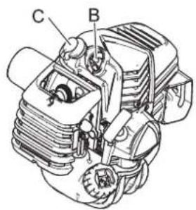
text_image
C B- Drain the fuel tank completely outdoors over bare ground. Do not drain fuel indoors.
- Alternately press and release the purge bulb a number of times to remove the fuel from the purge bulb.
- Start the engine and run it at idle speed until it comes to a natural stop.
- Move the ignition switch (A) to the Stop position.
- Once the product is sufficiently cool, wipe clean any grease, oil, dust, dirt and other materials on the outside of the trim-mer.
- Perform the periodic checks prescribed in this manual.
-
Check that the screws and nuts are tightened. Tighten up any that are loose.
-
Remove the spark plug (B) and add the appropriate quantity (around 10 mL) of clean, new 2-stroke engine oil to the cylinder via the spark plug hole.
- Place a piece of clean cloth over the spark plug hole.
- Pull 2 or 3 times on the starter grip to distribute the engine oil into the cylinder.
- Observe the piston location through the spark plug hole. Pull the recoil starter handle slowly until the piston reaches the top of its travel and leave it there.
- Fit the spark plug. (Do not connect the spark plug cap (C).)
- Fit the blade cover onto the trimmer blade and wrap the engine section in a plastic bag or other covering, and store in a dry, dust-free location out of reach of children.
| T302TS C302TS | |||
| External dimensions: Length × Width × Height (without cutting at- tachment) | 1799 × 349 × 344 mm 1799 | × 695 × 525 mm | |
| Mass:Unit without fuel, cutting attachment and harness (ISO11806-1: 2011)Unit with fuel, specified cutting attachment, guard and harnessUnit without fuel, cutting attachment, guard and harness | 6.4 kg7.5 kg5.8 kg | 6.6 kg8.2 kg6.1 kg | |
| Volume: Fuel tank (full) 710 mL | |||
| Fuel: GasolineOilMixture ratio | Regular grade petrol. Minimum 89 Octane unleaded petrol is recommended. Do not use fuel containing me-thyl alcohol or more than 10% of ethyl alcohol.Two stroke, air-cooled engine oil. ISO-L-EGD Standard (ISO/CD 13738), JASO FC,FD grade and Shindaiwa recommended oil.50:1 part (2%) | ||
| Cutting attachment:Nylon line cutting head (Cutting swath)ThreadNylon cord size (diameter)Nylon cord length | SF400 (508)Left-handed thread M10×1.25 pitch2.4 mm3.5 m | ||
| Gear Case: Gear ratio and lubricationRotational direction of output shaft viewed from above maximum rotational frequency of the spindle | 1.62 reduction and good quality lithium greaseAnticlockwise7720 r/min | ||
| Engine: TypeCarburettorMagnetoSpark plugStarterPower transmissionEngine displacementMaximum shaft brake power (ISO 8893)Fuel consumption at maximum engine powerRecommended maximum engine speed (With STD attachment in-stalled)Recommended engine idling speed | Air cooled two stroke, single cylinderDiaphragm typeFlywheel magneto - CDI systemNGK CMR7HRecoil starterAutomatic centrifugal clutch30.5 cm31.3 kW0.72 L/h10200 r/min2800 - 2900 r/min | ||
| 2006/42/ECVibration (ISO 22867) ahv,eqSound pressure level (ISO 22868) LpAeqSound power level (ISO 22868) LWARa | Left handleRight handleUncertainty KUncertainty KpAUncertainty KWAA | 2.9 m/s24.6 m/s21.2 m/s298.1 dB(A)1.5 dB(A)111.7 dB(A)2.1 dB(A) | |
These specifications are subject to change without notice.
The undersigned manufacturer:
YAMABIKO CORPORATION
1-7-2 Suehirocho
Ohme, Tokyo 198-8760
JAPAN
This declaration of conformity is issued under the sole responsibility of the manufacturer.
Declares that the hereunder specified new unit:
GRASS-TRIMMER/BRUSHCUTTER
Brand: shindaiwa
Type: T302TS/C302TS
natural_image
Technical line drawing of a mechanical assembly with three components (no text or symbols)Complies with:
* the requirements of Directive 2006/42/EC (use of harmonized standard EN ISO 11806-1: 2011)
* the requirements of Directive 2014/30/EU (use of harmonized standard EN ISO 14982: 2009)
* the requirements of Directive 2011/65/EU (use of harmonized standard EN 50581: 2012)
* the requirements of Directive 2000/14/EC
Conformity assessment procedure followed ANNEX V
Measured sound power level: 110 dB(A) T302TS, 110 dB(A) C302TS
Guaranteed sound power level: 113 dB(A) T302TS, 113 dB(A) C302TS
Serial Number 38001001 to 38100000
Tokyo, December 26th, 2018
YAMABIKO CORPORATION
Marayuki Timura
The authorized representative in Europe who is authorized to compile the technical file.
Company: CERTIFICATION EXPERTS B.V.
Address: P.O. box 5047, Merwedeweg 2, 3621 LR Breukelen, The Netherlands
Masayuki Kimura Mr. Richard Glaser
General Manager
Quality Assurance Dept.
MEMORANDUM
MEMORANDUM
YAMABIKO CORPORATION
1-7-2 Suehirocho, Ohme, Tokyo 198-8760 JAPAN
PHONE: 81-428-32-6118. FAX: 81-428-32-6145.
shindaiwa®
GB
X750235-1103
MANUEL D'UTILISATION COUPE-HERBE/DÉBROUSSAIL- LEUSE
T302TS
C302TS

AVERTISSEMENT
CE

LIRE ATTENTIVEMENT LES INSTRUCTIONS ET SUIVRE LES RÈGLES DE SECURITÉ.
LE NON-RESPECT DES RÈGLES DE SÉCURITÉ ENTRAÎNE UN RISQUE DE BLESSURE GRAVE.
text_image
Illustration showing a prohibition symbol over food waste, with people and items like bottles, documents, and a bottle nearby.
AVERTISSEMENT
natural_image
Illustration of clothing items including a shirt, necklace, tie, and sandal (no text or symbols)
AVERTISSEMENT
text_image
Labeled diagram of a person wearing a helmet and standing with multiple arms and legs numbered 1 to 8.natural_image
Line drawing of a first aid kit, medical device, and telephone (no text or symbols)text_image
Warning symbols and safety icons including warning, hazard, safety gear, and hazard signs with Chinese text.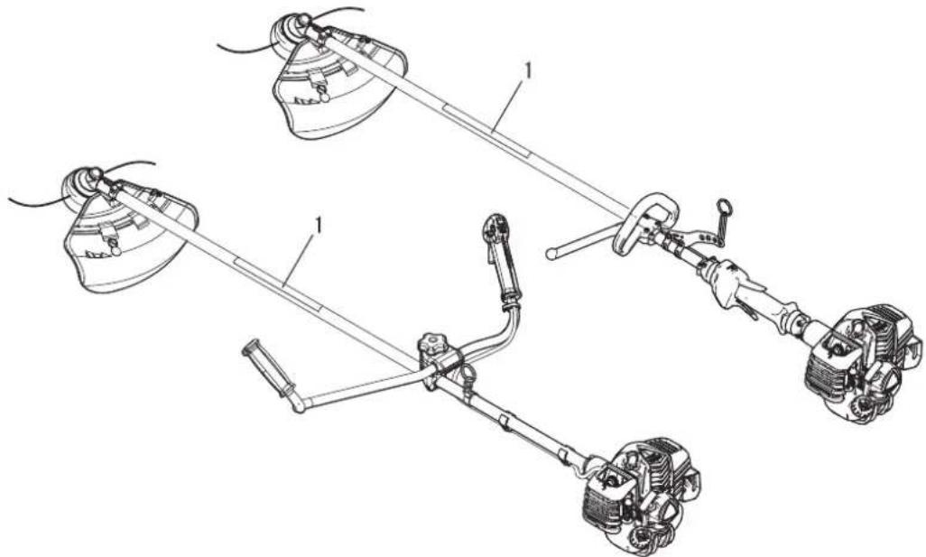
text_image
Technical diagram of automotive suspension system components with labeled parts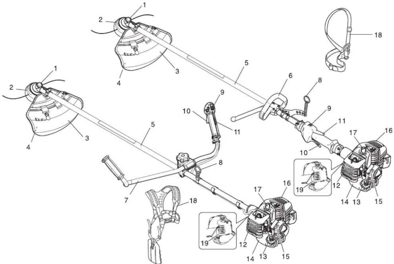
text_image
Technical diagram of a mechanical linkage system with numbered components and close-ups of internal parts.text_image
Technical diagram showing a medical device with labeled parts including a clamp, connector, and medical equipment.text_image
Technical diagram showing exploded view and labeled parts of a medical device with numbered componentstext_image
1 - 2 mm K L Jtext_image
Technical diagram of a device with labeled parts A and B, showing components like wires and components.text_image
Technical diagram of a mechanical assembly with labeled parts A through E, including a detailed inset view of a circular component.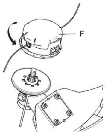
text_image
Fnatural_image
Illustration of two safety harnesses with rope and chain links, showing hand positioning and hanging weights (no text or symbols)text_image
HE F IG H I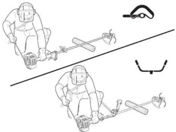
natural_image
Illustration of two identical winter sports gear with a roller and lever system, no text or symbols presenttext_image
Illustration showing a person digging with a shovel and a prohibition symbol, alongside two hand gestures holding hands.text_image
Technical diagram showing two mechanical assembly steps labeled A and B, with arrows indicating motion direction.text_image
Technical diagram illustrating a mechanical assembly process with labeled components and directional arrowsTaille
text_image
Technical diagram of a mechanical device with numbered components and directional arrows indicating motion or assembly.natural_image
Illustration of two workers using a long pole to measure a slope, with no text or symbols present.natural_image
Two workers in protective gear using a tool on a tree, labeled A and B (no text or symbols present)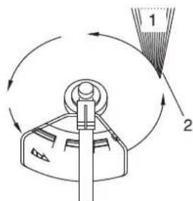
text_image
Diagram showing a mechanical or fluid system with labeled components and directional arrows indicating flow or movement.
text_image
Safety warning illustration showing a construction or inspection with a 'No' symbol and debris, alongside a grid background with grass and a broken pipe.natural_image
Illustration of a person using a grassy field with a small robot, no text or symbols presentnatural_image
Illustration of a worker spraying water with a curved pipe and directional arrows (no text or symbols)natural_image
Illustration of two workers using a tool to interact with a device, surrounded by grass (no text or symbols)text_image
Technical diagram of an electrical connector with labeled parts A and Btext_image
Diagram showing a car's seatbelt and cable connector with labeled parts A and Bnatural_image
Technical line drawing of a mechanical assembly with gears and housing (no text or symbols)natural_image
Technical line drawing of a mechanical assembly with labeled component A (no text or symbols beyond label)Admission d'air
natural_image
Technical line drawing of a mechanical engine assembly (no text or symbols)text_image
Technical diagram of a mechanical device with labeled parts A, B, and C, showing assembly or assembly steps.text_image
Technical diagram showing a mechanical assembly with labeled parts A, B, C, D and component E, including a circular component with a valve icon.text_image
Technical diagram of a mechanical assembly with labeled parts A through F, including a detailed inset view of a circular component.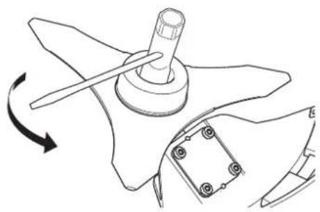
natural_image
Technical line drawing of a propeller with rotating shaft and mounting base (no text or symbols)natural_image
Simple line drawing of a human head with a dashed line indicating a trajectory or path (no text or symbols)text_image
Technical diagram showing four steps of a wire clamp or tool installation, labeled 2 to 4 with arrows indicating motion.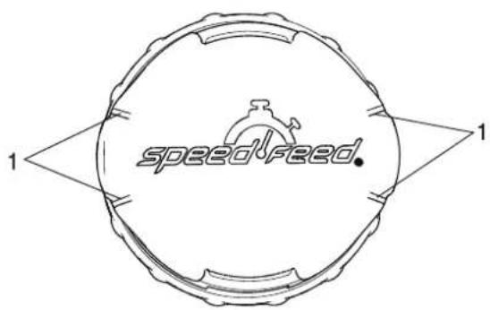
text_image
speedfeed 1 1text_image
A STOP A STOP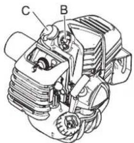
text_image
C Bnatural_image
Technical line drawing of a mechanical assembly with three components (no text or symbols)Est conforme :
text_image
Illustration showing a prohibition symbol over a group of people, with lab equipment and documents below.
WARNUNG
Vibration und Kälte
natural_image
Illustration of a person's clothing including a shirt, shorts, a necklace, a stop sign, and a pair of shoes (no text or symbols)
WARNUNG
text_image
Labeled diagram of a person wearing a helmet and standing with multiple arms and legs numbered 1 to 8.natural_image
Illustration of a first aid kit, medical sphygmoman, and telephone (no text or symbols)text_image
Warning symbols and safety icons including warning, hazard, helmet, hand gesture, gear, contact angle, and hazard signs with Chinese text.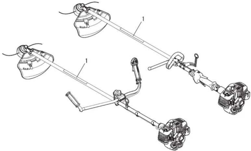
text_image
Technical diagram of automotive suspension system components with labeled parts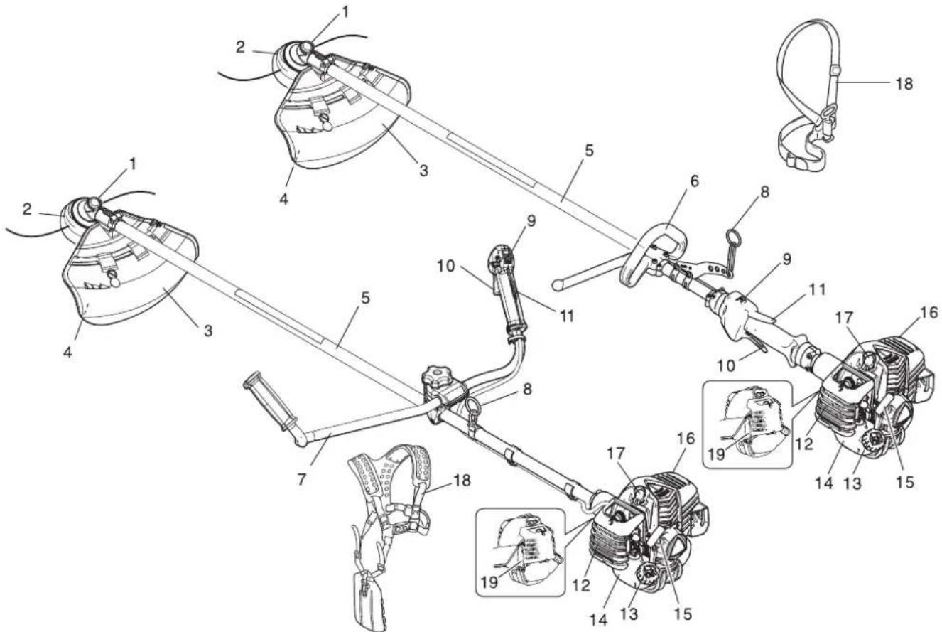
text_image
Technical diagram of a mechanical linkage system with numbered components and close-ups of internal parts.text_image
Technical diagram showing exploded view of medical or dental equipment with numbered components and labeled partstext_image
Technical diagram showing exploded view and labeled parts of a medical device with numbered componentstext_image
1 - 2 mm K L JVORSICHT
text_image
Technical diagram of a device with labeled parts A and B, showing internal components and connections.text_image
Technical diagram of a mechanical assembly with labeled parts A through E, including a detailed inset view of a circular component.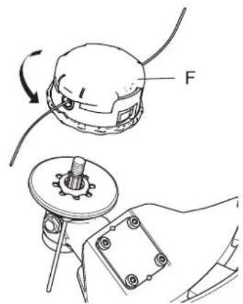
text_image
Fnatural_image
Illustration of two safety harnesses with rope and chain links, showing hand positioning and lifting mechanism (no text or symbols)text_image
HE F HG H I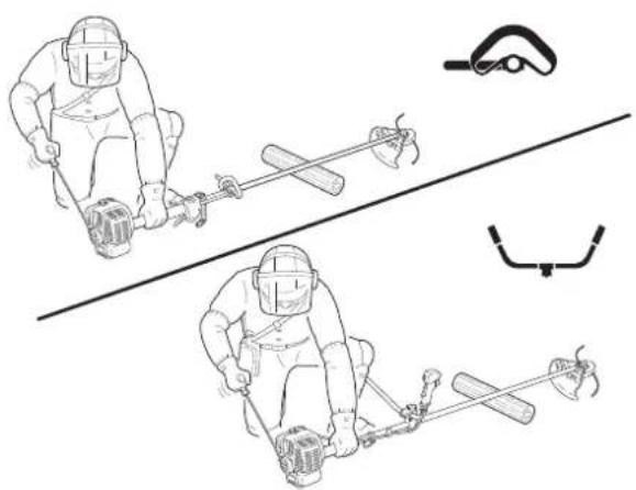
natural_image
Illustration of two identical winter sports gear with a tool, showing different motion poses (no text or symbols)text_image
Illustration showing a person using a tool to remove debris and two hand gestures with prohibition symbolstext_image
Technical diagram showing two mechanical assembly steps labeled A and B, with arrows indicating motion direction.text_image
Technical diagram illustrating a mechanical assembly process with labeled components and directional arrowsTrimmen
text_image
Technical diagram of a mechanical device with numbered components and dimension annotationsnatural_image
Illustration of two workers using a long polel tool to measure a circular object on grass (no text or symbols)natural_image
Illustration of two workers in protective gear using a manual tool, labeled A and B (no text or symbols on the diagram itself)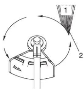
text_image
Diagram showing a mechanical device with labeled parts and directional arrows indicating motion or rotation.text_image
Safety warning illustration showing a person using a device to stop over grass, with a no-smoking symbol nearby.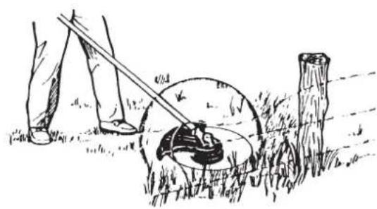
natural_image
Illustration of a person using a tool to clean grass with a circular device, no text or symbols presentnatural_image
Illustration of a worker in protective gear standing on a curved ramp with directional arrows (no text or symbols)Unkraut mähen
natural_image
Illustration of two workers using a tool to measure a slope, with no text or symbols present.text_image
Technical diagram of an electrical connector assembly with labeled parts A and Btext_image
Diagram showing car air intake system with labeled components A and B, including a valve and connector.natural_image
Technical line drawing of a mechanical engine assembly (no text or symbols visible)natural_image
Technical line drawing of a mechanical assembly with labeled component A (no text or symbols beyond label)Luftzufuhröffnung
natural_image
Technical line drawing of a mechanical engine assembly (no text or symbols visible)text_image
Technical diagram of a mechanical assembly with labeled parts A, B, and Ctext_image
Technical diagram showing a device's internal components and assembly steps, labeled A, B, C, D, E with directional arrows indicating movement.text_image
Technical diagram of a mechanical assembly with labeled parts A through F, including a detailed inset view of the component.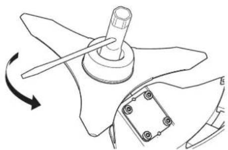
natural_image
Technical line drawing of a mechanical component with rotation arrow (no text or symbols)text_image
Technical diagram showing a mechanical part with an eye and a 30-degree angled cut, including dimension lines.Nylonfaden einlegen
text_image
Technical diagram showing four steps of a manual tool application with labeled parts 2, 3, and 4.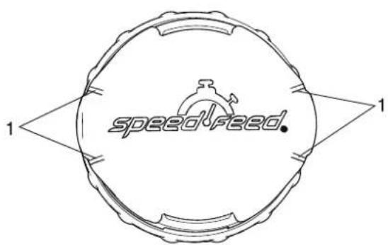
text_image
speedFeed 1 1text_image
A STOP A STOP
text_image
C Bnatural_image
Technical line drawing of a mechanical assembly with three components (no text or symbols)Folgendes erfüllt:
natural_image
Illustration of a shirt, necklace, handbag, and pair of shoes (no text or symbols)text_image
Labeled diagram of a person wearing a hard hat and standing with eight numbered parts for identification.
AVVERTENZA
natural_image
Illustration of a first aid kit, medical sphygmoman, and mobile phone (no text or symbols)text_image
Warning symbols and safety icons including warning, hazard, gear, contact, and hazard signs with Chinese text.
text_image
Technical diagram of automotive suspension system components with labeled parts
text_image
Technical diagram of a mechanical linkage system with numbered components and close-ups of internal parts.text_image
Technical diagram showing exploded view of medical or dental equipment with numbered components and labeled partstext_image
Technical diagram showing exploded view and labeled parts of a medical device with numbered componentstext_image
1 - 2 mm K L JATTENZIONE
text_image
Technical diagram of a mechanical assembly with labeled parts A through E, including a detailed inset view of a circular component.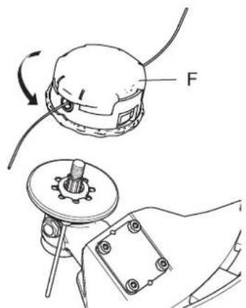
text_image
Technical diagram showing mechanical assembly with labeled component 'F' and directional arrow indicating rotationnatural_image
Illustration of two safety harnesses with rope and chain links, showing hand positioning and lifting (no text or symbols)text_image
HE F IG H I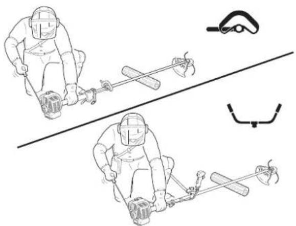
natural_image
Illustration of two workers in protective gear using a tool, with no visible text or symbolstext_image
Illustration showing a person digging with a shovel and prohibition symbols, alongside two hand gestures holding hands with crossed-out signs.text_image
Technical diagram showing two mechanical assembly steps labeled A and B, with arrows indicating motion direction.text_image
Technical diagram illustrating a mechanical assembly process with labeled components and directional arrowsTaglio
text_image
Technical diagram of a mechanical device with numbered components and dimension annotationsnatural_image
Illustration of two workers using a long-handled tool to measure a circular motion on grass (no text or symbols)natural_image
Illustration of two workers in protective gear using a manual tool, labeled A and B (no text or symbols on the figures themselves)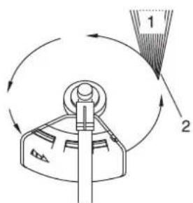
text_image
Diagram showing a mechanical device with labeled parts and directional arrows indicating motion or rotation.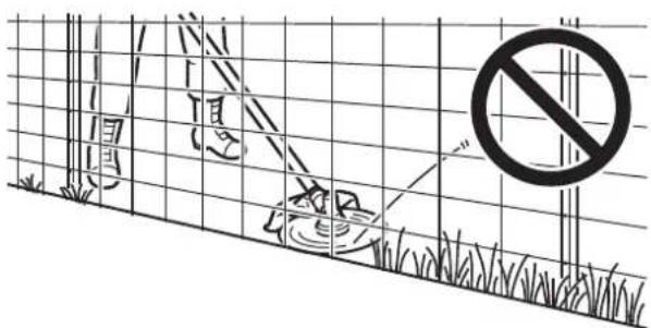
text_image
Diagram showing a fence with grass, a trash bin, and a prohibition symbol with arrowsnatural_image
Illustration of a person using a tool to lift a circular object in a grassy field, with a post and tree stump nearby (no text or symbols)natural_image
Illustration of a worker using a tool to interact with a curved mechanical device (no text or symbols present)natural_image
Illustration of two workers using a long-handled tool to measure a slope in grass (no text or symbols)text_image
Technical diagram of an automotive electronic component with labeled parts A and Btext_image
Diagram showing car component parts with labeled parts A, B, and a connector or connector.natural_image
Technical line drawing of a mechanical engine assembly (no text or symbols visible)natural_image
Technical line drawing of a mechanical assembly with labeled component A (no text or symbols beyond label)Presa d'aria
natural_image
Technical line drawing of a mechanical assembly with labeled component A (no text or symbols beyond label)text_image
Technical diagram of a mechanical device with labeled parts A, B, and Ctext_image
Technical diagram showing a mechanical assembly with labeled parts A, B, C, D and component E, including a circular component with a knob.text_image
Technical diagram of a mechanical assembly with labeled parts A through F, including a detailed inset view of component C.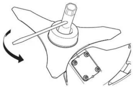
natural_image
Technical line drawing of a mechanical component with a rotating arrow indicating rotation (no text or symbols)Verifica della lama
natural_image
Simple line drawing of a human head with a dashed line indicating alignment or projection (no text or symbols)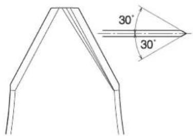
text_image
30° 30°text_image
Technical diagram showing four steps of a manual tool manipulation or assembly procedure, labeled 2 to 4.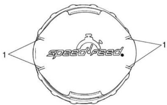
text_image
speedfeed.text_image
A STOP A STOP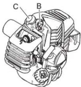
text_image
C Bnatural_image
Technical line drawing of a mechanical assembly with three components (no text or symbols)È conforme a:
text_image
Illustration showing a person holding a bottle and a cigarette with a no-smoking symbol, surrounded by other items including a bottle, a glass, and a paper.natural_image
Illustration of a first aid kit, medical sphygmoman, and telephone (no text or symbols)text_image
Warning symbols and safety icons including warning, hazard, safety gear, and various physical hazards with Chinese labels.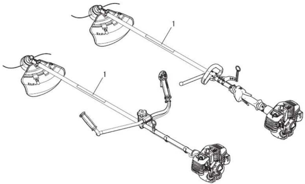
text_image
Technical diagram of a vehicle suspension system with labeled components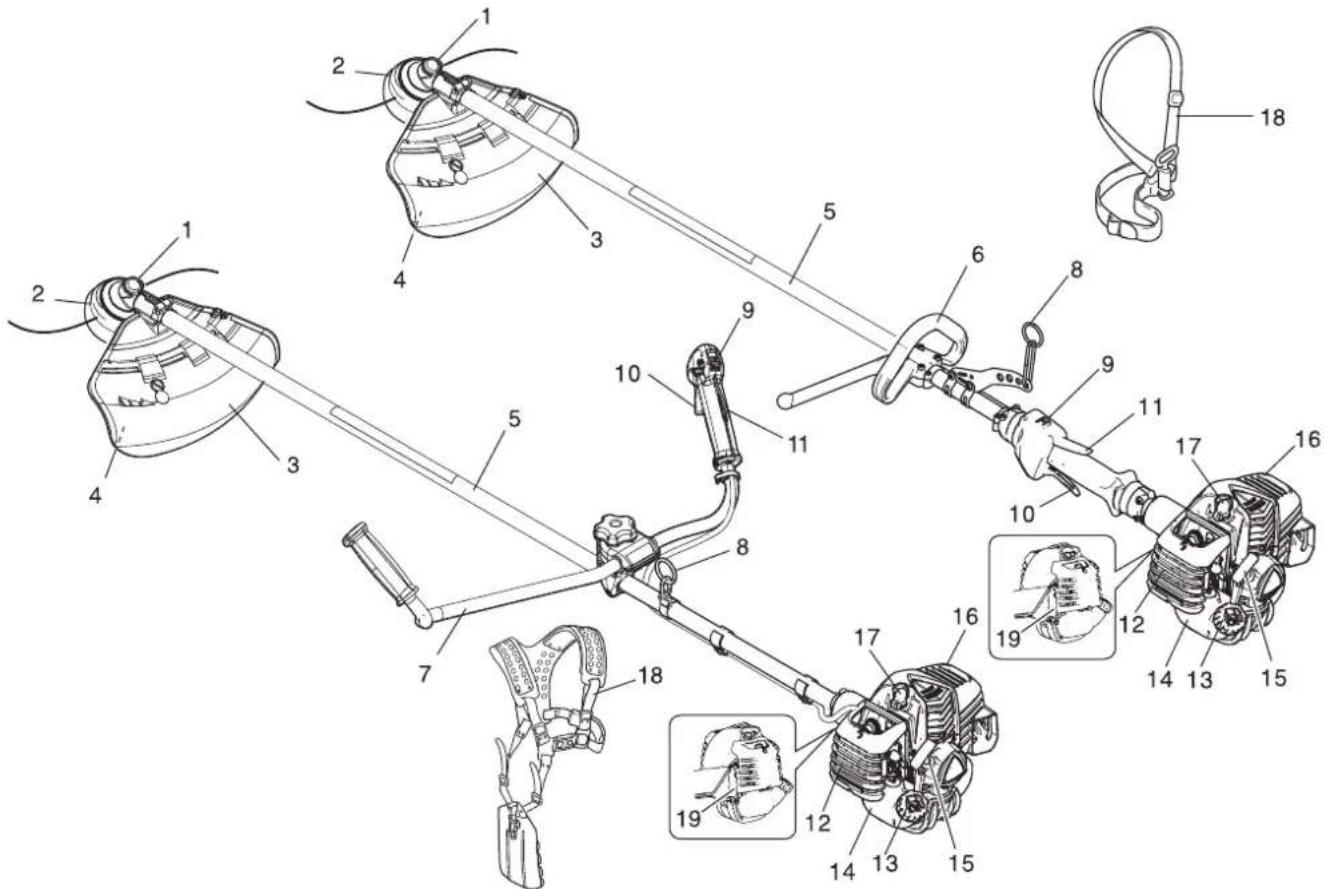
text_image
Technical diagram of a mechanical linkage system with numbered components and close-ups of parts labeled 12 through 19.text_image
Technical diagram showing a medical device with labeled parts including a clamp, grip, and connector.text_image
Technical diagram showing exploded view and labeled parts of a medical device with numbered componentstext_image
1 - 2 mm K L J
PRECAUCIÓN
text_image
Technical diagram of a mechanical assembly with labeled parts A through E, including a detailed inset view of a circular component.text_image
Technical diagram showing mechanical assembly with labeled component 'F' and a rotating component
PRECAUCIÓN
text_image
Technical diagram showing two steps of climbing a rope using harnesses and chains, with directional arrows indicating movement.text_image
HE F HIG H I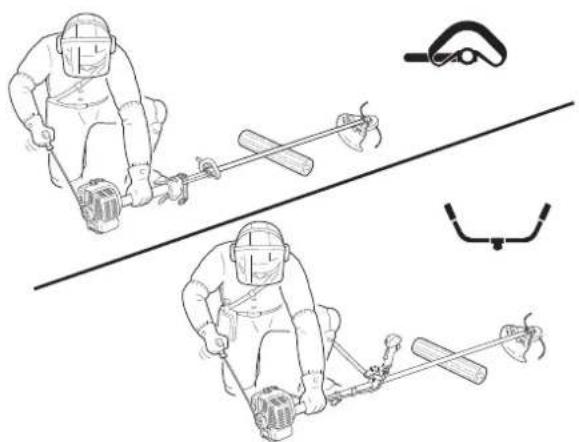
natural_image
Illustration of two identical winter sports gear with dynamic poses and a pair of wire tools, no text or symbols present.Arranque de un motor caliente
text_image
START A B C D A START C B DParada del motor
text_image
A STOP B A STOP Btext_image
Illustration showing a person digging with a shovel and a hand holding a tool, accompanied by prohibition symbols.Uso del arnés
text_image
Technical diagram showing two mechanical assembly steps labeled A and B, with arrows indicating motion direction.text_image
Diagram illustrating a mechanical process with labeled components and directional arrows, showing a tool interacting with a base and then to a circular component.text_image
Technical diagram of a mechanical device with numbered components and dimension annotationsnatural_image
Illustration of two workers in hard hats using a tool to measure a slope (no text or symbols)natural_image
Two illustrations of a person using a tool to clean or walk, labeled A and B (no text or symbols on the figures themselves)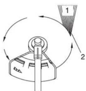
text_image
Diagram showing a mechanical device with labeled parts 1 and 2, indicating a rotation or assembly process.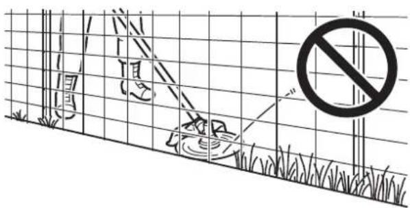
text_image
Diagram showing a fence with grass, a person holding a device, and a prohibition symbol in the background.natural_image
Illustration of a person using a tool to lift a circular object over grass, with a post and tree stump nearby (no text or symbols)natural_image
Illustration of two workers using a tool to measure a slope, with no text or symbols present.text_image
Technical diagram of an electrical connector assembly with labeled parts A and Btext_image
Technical diagram showing a mechanical component with labeled parts A, B, and a circular connector.natural_image
Technical line drawing of a mechanical assembly with gears and springs (no text or symbols)natural_image
Technical line drawing of a mechanical assembly with labeled component A (no text or symbols beyond label)Entrada de aire
natural_image
Technical line drawing of a mechanical device with labeled component A (no text or symbols beyond label)text_image
Technical diagram of a mechanical device with labeled parts A, B, and C, showing assembly or assembly steps.text_image
Technical diagram showing a mechanical assembly with labeled parts A, B, C, D, and E, including a circular component with a steering wheel.text_image
Technical diagram of a mechanical assembly with labeled parts A through F, including a detailed inset view of a circular component.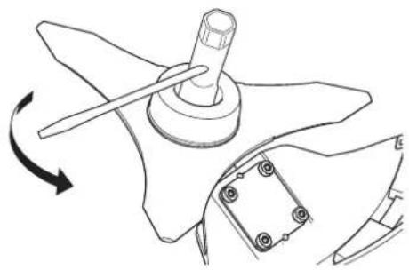
natural_image
Technical line drawing of a mechanical component with a rotating arrow indicating rotation (no text or symbols)natural_image
Simple line drawing of a curved object with a dashed line and an arrow pointing to it, no text or symbols present.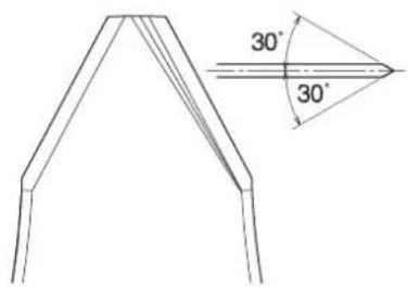
text_image
30° 30°text_image
Technical diagram showing four steps of a manual tool application with labeled parts 2, 3, and 4.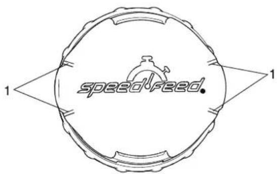
text_image
speedfeed.text_image
A STOP A STOP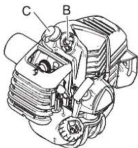
text_image
C BCORTABORDES/DESBROZADORA
Marca: shindaiwa
Tipo: T302TS/C302TS