
FWA1012VC - Stroller Advantech - Free user manual and instructions
Find the device manual for free FWA1012VC Advantech in PDF.
| Product type | Stroller |
| Brand | Advantech |
| Model | FWA1012VC |
| Dimensions (folded) | 90 x 60 x 30 cm |
| Dimensions (unfolded) | 100 x 70 x 100 cm |
| Weight | 12 kg |
| Recommended age | From birth to 3 years |
| Maximum weight capacity | 15 kg |
| Frame material | Aluminum |
| Fabric material | Polyester |
| Wheel type | Rubber wheels, swivel front |
| Brakes | Pedal brake on rear wheels |
| Seat recline | Multiple positions, recline up to 170° |
| Adjustable handle | Yes, height adjustable |
| Harness | 5-point harness |
| Canopy | With visibility window, UV 50+ protection |
| Storage basket | Yes, underneath |
| Folding | Compact, with locking system |
| Maintenance | Clean with a damp cloth |
| Safety | Compliant with EN 1888 standards |
| Included accessories | Rain cover, footmuff |
| Spare parts | Available on manufacturer's website |
| Warranty | 2 years |
Frequently Asked Questions - FWA1012VC Advantech
User questions about FWA1012VC Advantech
0 question about this device. Answer the ones you know or ask your own.
Ask a new question about this device
Download the instructions for your Stroller in PDF format for free! Find your manual FWA1012VC - Advantech and take your electronic device back in hand. On this page are published all the documents necessary for the use of your device. FWA1012VC by Advantech.
USER MANUAL FWA1012VC Advantech
ADVANTECH USER MANUAL
POWER OVER ETHERNET CONTROL UTILITY
Revision 2.0
Revision History
| Date [mm/dd/yyyy] | Revision | Modifications |
| 03/13/2024 | 2.0 | Ed2 office release |
| 02/20/2024 | 1.1 | - Update based on v1.14 |
| 10/23/2019 | 1.0 | Ed1 office release |
| 07/22/2019 | 0.5 | Update application note. Remove -GEPITLVL and -INTCBTEST commands and corresponding APIs. Change API return values to signed value. Add -CHKINT command. Replace switch i2c mux to GPIO device cmd with ch 5.2.1 Add description for multi-process and mutex in chap4 |
| 10/17/2019 | ||
| 08/22/2018 | 0.4 | Updated draft content by review |
| 07/20/2018 | 0.3 | Change figure format. |
| 06/25/2018 | 0.2 | Add set priority of different ports and test in application note |
| 04/18/2018 | 0.1 | Add interrupt API and commands |
| 03/16/2018 | 0.0 | Initial version |
Table of Contents
1. INTRODUCTION 8
1.1 SCOPE 8
1.2 TERMINOLOGY 8
1.3 POE ARCHITECTURE OVERVIEW 9
2. OVERVIEW 10
2.1 HOST INTERFACE 10
2.2 CONTROL 10
2.3 POWER SOLUTION 10
2.4 IDENTIFY DIFFERENT POE DEVICES (NMC/SOC) 10
2.5 LED INDICATION 11
2.6 ERROR CODES 12
3. LIBAPOE -ADVANTECH POE LIBRARY 14
3.1 SUPPORTED DISTRIBUTIONS 14
3.2 HEADERFILE 15
3.3 API COMMAND LIST 24
3.4 HOW TO USE THE API 26
3.5 API FUNCTIONS 26
3.5.1 APOECU Message Output Level 26
3.5.1.1 apoe_err apoe_set_message_level(). 26
3.5.2 APOECU Open/Close 26
3.5.2.1 apoe_err apoe_open(). 26
3.5.2.2 apoe_err apoe_close [] 27
3.5.3 APOE Information 27
3.5.3.1 apoe_err apoe_get_lib_version() 27
3.5.3.2 apoe_err apoe_get_fw_version() 27
3.5.4 APOECU System Operations 28
3.5.4.1 apoe_err apoe_reset(). 28
3.5.4.2 apoe_err apoerestoreFACTORY_default( )............ 28
3.5.4.3 apoe_err apoe_save_system_settings() 29
3.5.5 APOE Port Operations 29
3.5.5.1 apoe_err apoe_set_poe_device_parameters[] 29
3.5.5.2 apoe_err apoe_get_poe_device_status() 30
3.5.5.3 apoe_err apoe_set_eth_port_enable_disable() 31
3.5.5.4 apoe_err apoe_set_eth_port_force_power[] 31
3.5.5.5 apoe_err apoe_set_eth_port_power_limit(). 32
3.5.5.6 apoe_err apoe_get_eth_port_power_limit() 32
3.5.5.7 apoe_err apoe_set_eth_portpriority() 33
3.5.5.8 apoe_err apoe_get_eth_portpriority() 33
3.5.5.9 apoe_err apoe_get_eth_port_status(). 33
3.5.5.10 apoe_err apoe_get_eth_port_EXTENDED_status(). 36
3.5.5.11 apoe_err apoe_get_eth_port_powermeasurements() 38
3.5.5.12 apoe_err apoe_get_eth_port_data() 38
3.5.5.13 apoe_err apoe_get_all_port_data(). 40
3.5.6 APOE Power Bank Functions 41
3.5.6.1 apoe_err apoe_get_power_management_method(). 41
3.5.6.2 apoe_err apoe_get_total_power(). 42
3.5.6.3 apoe_err apoe_set_power_banks() 43
3.5.6.4 apoe_err apoe_get_power_banks() 43
3.5.6.5 apoe_err apoe_get_power_supply_parameters() 44
3.5.6.6 apoe_err apoe_get_power_supply_voltage_current( ). 45
3.5.6.7 apoe_err apoe_set_power_bank_power_source_type() 45
3.5.7 APOE Register Read/Write Debug Functions 46
3.5.7.1 apoc_err apoc_get_register_value() 46
3.5.7.2 apoe_err apoe_set_register_value(). 46
3.5.8 APOE Interrupt 47
3.5.8.1 apoe_err apoe_clear_interrupt() 47
3.5.8.2 apoe_set_interrupt_settings() 47
3.5.8.3 apoe_err apoe_get_interrupt_settings
4. APOECU 49
4.1 ./APOECU 49
4.2 ./APOECU-V 50
4.3 ./APOECU-VF 50
4.4 ./APOECU-VP 50
4.5 ./APOECU-SEPED 51
4.6 ./APOECU-SEPFP 51
4.7 ./APOECU-SEPP 51
4.8 ./APOECU-SEPPL 52
4.9 ./APOECU-GEPPL 52
4.10 ./APOECU-GEPP 53
4.11 ./APOECU-GEPES 53
4.12 ./APOECU-GEPM 54
4.13 ./APOECU-GEPD 55
4.14 ./APOECU-GTP 56
4.15 ./APOECU-GAPD 56
4.16 ./APOECU-SPB 58
4.17 ./APOECU-GPB 59
4.18 ./APOECU-GPSP 60
4.19 ./APOECU-GPSVC 61
4.20 ./APOECU-SEPINT 61
4.21 ./APOECU-GEPINT 62
4.22 ./APOECU-CLRINT 63
4.23 ./APOECU-CHKINT 63
5. APPLICATION NOTE 65
5.1 CONNECTING A POE PORT TO A NORMAL NIC PORT.. 65
5.2 POE INTERRUPT WITH FWA-3260 65
5.2.1 Using kernel driver to control i2c-mux and i2c to gpio device.. 65
5.2.2 Enable PoE interrupt function.. 67
5.2.3 Read the status of i2c to GPIO device 69
ADVANTECH
Enabling an Intelligent Planet

5.3 POE INTERRUPT WITH FWA-1012VC 70
5.3.1 Enable PoE Interrupt Function 70
5.3.2 Read the Status of Denverton's GPIO 71
5.4 SETTING AND TESTING THE PRIORITY OF DIFFERENT PORTS 71
List of Figures
Figure 1: PoE Overview. 9
Figure 2: Control Plan between a Motherboard and PoE Devices. 10
List of Tables
Table 1: Terminology 8
Table 2: Activity LED Behavior. 12
Table 3: Error Codes. 13
Table 4: Supported API Functions 25
Table 5: API Function 'apoe_set_message_level' Error Codes. 26
Table 6: API Function 'apoe_open' Error Codes 26
Table 7: API Function 'apoe_close' Error Codes 27
Table 8: API Function 'apoe_get_lib_version' Error Codes 27
Table 9: API Function 'apoe_get_fw_version' Error Codes 28
Table 10: API Function 'apoe_reset' Error Codes 28
Table 11: API Function 'apoeRESTOREFACTORY_default' Error Codes 29
Table 12: API Function 'apoe_save_system_settings' Error Codes. 29
Table 13: API Function 'apoe_set_poe_device_parameters' Error Codes. 29
Table 14: API Function 'apoe_get_poe_device_status' Error Codes. 31
Table 15: API Function 'apoe_set_eth_port_enable_disable' Error Codes 31
Table 16: API Function 'apoe_set_eth_port_force_power' Error Codes 32
Table 17: API Function 'apoe_set_eth_port_power_limit' Error Codes 32
Table 18: API Function 'apoe_get_eth_port_power_limit' Error Codes. 33
Table 19: API Function 'apoe_set_eth_port_priority' Error Codes 33
Table 20: API Function 'apoe_get_eth_port_priority' Error Codes. 33
Table 21: API Function 'apoe_get_eth_port_status' Error Codes 36
Table 22: API Function 'apoe_get_eth_port_EXTENDED_status' Error Codes 38
Table 23: API Function 'apoe_get_eth_port_powermeasurements' Error Codes 38
Table 24: API Function 'apoe_get_eth_port_data' Error Codes 39
Table 25: API Function 'apoe_get_all_port_data' Error Codes 40
Table 26: API Function 'apoe_get_power_management_method' Error Codes. 42
Table 27: API Function 'apoe_get_total_power' Error Codes 43
Table 28: API Function 'apoe_set_power_banks' Error Codes 43
Table 29: API Function 'apoe_get_power_banks' Error Codes 44
Table 30: API Function 'apoe_get_power_supply_parameters' Error Codes. 45
Table 31: API Function 'apoe_get_power_supply_voltage_current' Error Codes. 45
Table 32: API Function 'apoe_set_power_bank_power_source_type' Error Codes. 46
ADVANTECH
Enabling an Intelligent Planet
Table 33: API Function 'apoe_get_register_value' Error Codes 46
Table 34: API Function 'apoe_set_register_value' Error Codes 47
Table 35: API Function 'apoe_clear_interrupt' Error Codes. 47
Table 36: API Function 'apoe_set_interrupt' Error Codes. 48
Table 37: API Function 'apoe_get_interrupt' Error Codes 48
1. INTRODUCTION
1.1 Scope
This document describes the Advantech Power over Ethernet Control utility (APOECU) and related software APIs. Please check the utility release on the Advantech website or contact with your Advantech representative for details on supported products and SW versions.
1.2 Terminology
Table 1: Terminology
| Term | Description |
| API | Application programming interface |
| eth device | Ethernet device |
| FW | Firmware |
| Host system | x86 system |
| PoE | Power over Ethernet |
| PoE MCU | PoE micro controller |
| APOECU | Advantech PoE Control Utility |
| LED | Light emitting diode |
| Libapoe | Static library for Advanced PoE |
| NIC | Network interface controller |
| NMC | Network mezzanine card |
| OS | Operating system |
| PCIe | PCI Express |
| SW | Software |
| UART | Universal asynchronous receiver/transmitter |
| USB | Universal Serial Bus |
1.3 PoE Architecture Overview
PoE may be supported on Ethernet ports hosted either directly on a motherboard such as onboard network ports or via add-in cards such as NMCs or PCIe NIC cards.
LAN controllers, aka NICs, are connected to the CPU(s) via the PCIe interface.
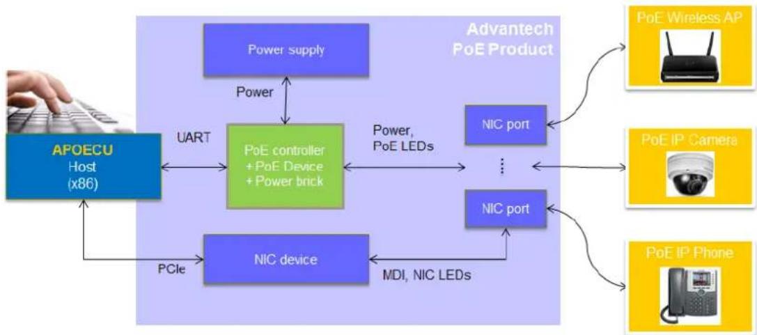
Figure 1: PoE Overview
APOECU gives control over PoE functions through our products. For example, ethdev can be used to map to physical ports, to enable/disable PoE per ports, to configure AT/AF, power limitations, temperature, voltage, current, and port priority, and to get the port status. APOECU can support two types of PoE controller (PD69104 and PD69200) and can use the proper communication with different controllers. Please note that different controllers have different capabilities (see Chapter 3.5).
Advantech also provides the PoE library for the advanced user to implement their own applications running on the host system, to access and modify the behaviour of the PoE MCUs, and to activate or use additional features via API. The interface between the host SW and the PoE MCUs is a UART interface. The PoE library is designed as a user space library and communicates directly with the NICs, allowing multiple SW instances to be run in parallel.
2. OVERVIEW
2.1 Host Interface
The Advantech PoE mechanism adopts a UART connection between the host system and the PoE MCU(s).
2.2 Control
Mostly, a centralized control application or OS is used to manage PoE on the system. In such a scenario, the control plane can still independently control the PoE controllers.
2.3 Power Solution
PoE solutions require an external power source via an extremal cable from the system to the PoE device. This means that NMC-type PoE is not field side removable.
2.4 Identify Different PoE Devices (NMC/SOC)
The host system in Figure 2 uses USB <-> UART to identify and communicate with the PoE controller. Advantech NMC type PoE card also supports connection to the PoE controller on host system through UART port directly as in Figure 1. The interface can't be changed after it has been manufactured.
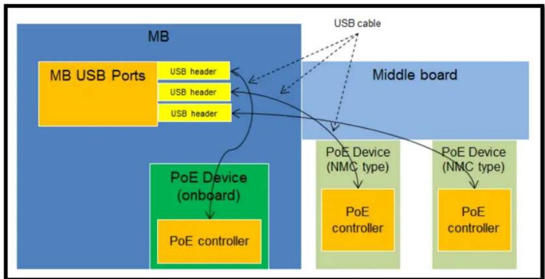
Figure 2: Control Plan between a Motherboard and PoE Devices
2.5 LED Indication
Advantech Advanced PoE has an LED on the LAN connector to indicate the current PoE state of each port. Please note LED doesn't support 10 Mbps Link/Active.
| LED Indicator | |||||
| PoE LED | LINK/ACT/SPD LED | ||||
| PoE LED | LINK/ACT/SPD LED | ||||
| PoE LED | Behavior | LINK/ACT/SPD LED | Behavior | ||
| All | PD69200 | PD69104 | |||
| PoE Off | LED off | 100, Link | Yellow on | ||
| PoE On | LED on | 100, Active | Yellow blinking | ||
| PoE is off, something wrong | Blinking | 1Hz:(Port power is not active, overload or short circuit is detected on port output line) | 3.3Hz (All ports)Vmain is out of range or over temp | 1000, Link | Green on |
| 0.5Hz(A valid POE load is connected to port output lines, but PSE has no sufficient power for supplying the required load power.) | 0.8 HzPort overloadPort shortcircuitPort failed atstartup | 1000, Active | Green blinking | ||
| 0.4HzPowerManagement event | No Link | Off | |||
Table 2: Activity LED Behavior
2.6 Error Codes
| Error Code | Name | Comment |
| -128 | APOE_ERR_OPEN_FILE | Failed to open the file (cannot open the file or the file does not exist) |
| -125 | APOE_ERR_CLOSE_FILE | Failed to close the file |
| -119 | APOE_ERR_INTERFACE_OPEN | No PoE control interface found, (Please check your the system). |
| -116 | APOE_ERR_DATA_FORMAT | UART RX message error |
| -110 | APOE_ERRCOMMUNICATION | UART communication error |
| -109 | APOE_ERRParam_OUT_OFBOUND | Input parameter invalid |
| -108 | APOE_ERRParam_null_POINTER | Input array invalid |
| -107 | APOE_ERR_INIT | APOE library needs to be initialized before a function can be called |
| -106 | APOE_ERR_COMMAND_NOT_support | Command not supported by this PoE MCU |
| -105 | APOE_ERR(GPIO_SET | Set UART pin error |
| -104 | APOE_ERR_OPEN_DIR | Open directory error |
| -103 | APOE_ERRNIC_NOTEXIST | Cannot find the NIC name |
| -102 | APOE_ERRNIC_NO_POE | The NIC does not support PoE |
| -80 | APOE_ERRCOMMUNICATION_TIMEOUT | Communication timeout |
| -32 | APOE_NACK_CMD | Command received, but "Sub" fields do not match |
| -31 | APOE_NACK_PARAM | Command received, but "Key" fields do not match |
Table 3: Error Codes
| -30 | APOE_NACK_CS | Command received, but command checksum incorrect |
| -28 | APOE_FW_ERROR | Get system status telemetry: PoE controller error |
| -27 | APOE_FW_UPGRADE_NEEDED | Get system status telemetry: FW download is needed |
3. LIBAPOE -ADVANTECH POE LIBRARY
Advantech provides a static Linux library (libapoe.a) and corresponding header file (libapoe.h) to integrate PoE control into customized applications.
3.1 Supported Distributions
Libapoe is a generic Linux user space library and thus is expected to work with most Linux distributions.
Advantech uses up-to-date Ubuntu distributions (4.13.0-36-generic) to perform software quality assurance. For more details, please refer to the release notes delivered as part of APOECU.
3.2 Header File
The header file exports/provides common definitions of the API commands. A brief introduction is provided here for reference only. Please check the header file for more details:
See Section 2.6 for the error code definitions.
ifndef_libAPOE_H
    #define LibAPOE_H
#include "apoe_cmd_reg_var.h"
#define APOE.libmajOR_VERSION 1
#define APOE.libMinor_VERSION 2
#define PROTOCOL_VERSION MajOR 1
#define PROTOCOL_VERSIONMinor O
/* Global variable */
struct apoe_system_environment_info hdr apoe_system_environment_info;
struct apoe.eth_deviceMapping hdr
apoe.eth_deviceMapping[MAXIMUM_POE_PORT_NUMBER];
/* Macros for 4.1.6 Get System Status */
#define apoe_cpu_status_1_is_controller_error(x) ((x & 0x01) == 0x01)
#define apoe_cpu_status_1_is_firmware_download_is_required(x) ((x & 0x02) == 0x02)
#define apoe_cpu_status_2_is_memory_error(x) ((x & 0x01) == 0x01)
#define apoe_cpu_status_2_is-less Than_eight_poe_device(x) ((x & 0x02) == 0x02)
#define apoe_isFACTORY_default(x) ((x & 0x01) == 0x01)
#define apoe_device_0_is_fail_or_do_not Exist(x) ((x & 0x01) == 0x01)
#define apoe_device_1_is_fail_or_do_not Exist(x) ((x & 0x02) == 0x02)
#define apoe_device_2_is_fail_or_do_not Exist(x) ((x & 0x04) == 0x04)
#define apoe_device_3_is_fail_or_do_not Exist(x) ((x & 0x08) == 0x08)
#define apoe_device_4_is_fail_or_do_not Exist(x) ((x & 0x10) == 0x10)
#define apoe_device_5_is_fail_or_do_not Exist(x) ((x & 0x20) == 0x20)
#define apoe_device_6_is_fail_or_do_not Exist(x) ((x & 0x40) == 0x40)
#define apoe_device_7_is_fail_or_do_not Exist(x) ((x & 0x80) == 0x80)
define apoe_device_0_is_disconnect_due_to_overheat(x) (x\& 0x01) == 0x01 #define apoe_device_1_is_disconnect_due_to_overheat(x) (x\& 0x02) == 0x02 #define apoe_device_2_is_disconnect_due_to_overheat(x) (x\& 0x04) == 0x04 #define apoe_device_3_is_disconnect_due_to_overheat(x) (x\& 0x08) == 0x08 #define apoe_device_4_is_disconnect_due_to_overheat(x) (x\& 0x10) == 0x10 #define apoe_device_5_is_disconnect_due_to_overheat(x) (x\& 0x20) == 0x20 #define apoe_device_6_is_disconnect_due_to_overheat(x) (x\& 0x40) == 0x40 #define apoe_device_7_is_disconnect_due_to_overheat(x) (x\& 0x80) == 0x80 #define apoe_device_0_is_temp alarm(x) (x\& 0x01) == 0x01 #define apoe_device_1_is_temp alarm(x) (x\& 0x02) == 0x02 #define apoe_device_2_is_temp alarm(x) (x\& 0x04) == 0x04 #define apoe_device_3_is_temp alarm(x) (x\& 0x08) == 0x08 #define apoe_device_4_is_temp alarm(x) (x\& 0x10) == 0x10 #define apoe_device_5_is_temp alarm(x) (x\& 0x20) == 0x20 #define apoe_device_6_is_temp alarm(x) (x\& 0x40) == 0x40 #define apoe_device_7_is_temp alarm(x) (x\& 0x80) == 0x80 #define apoe_int_is_any_port_turn_on(x) (x\& 0x01) == 0x01 #define apoe_int_is_any_port_turn_off(x) (x\& 0x02) == 0x02 #define apoe_int_is_any_port_detector_unsuccessful(x) (x\& 0x04) == 0x04) #define apoe_int_is_any_port_disconnect_due_to_fault(x) (x\& 0x08) == 0x08 #define apoe_int_is_any_port_disconnect_due_to_under_load(x) (x\& 0x10) == 0x10 #define apoe_int_is_any_port_disconnect_due_to_over_load(x) (x\& 0x20) == 0x20 #define apoe_int_is_any_port_disconnect_due_to_pm(x) (x\& 0x40) == 0x40) #define apoe_int_is_any_port_power_up-denied(x) (x\& 0x80) == 0x80) #define apoe_int_is_any_device_disconnect_due_to_high_temp(x) (x\& 0x100) == 0x100) #define apoe_int_is_any_device_temp_alarm(x) (x\& 0x200) == 0x200) #define apoe_int_is_any_device_fail(x) (x\& 0x400) == 0x400) // O x800 reserved
define apoe_int_is_no_more_connect(x) (x\& 0x1000) == 0x1000) #define apoe_int_is_vamin_fault(x) (x\& 0x2000) == 0x2000) // O x4000, O x800 reserved
/* If cpu_status_1 is firmware download is required, format changing /#define apoe.boot_up_fail_infoneed_download(x) (x\& 0xO1) == 0xO1) #define apoe.boot_up_fail_info_hw_error(x) (x\& 0XO2)==O× O2)
#define apoe.boot_up_fail_info_sys_type_error(x) ((x & 0x04) == 0x04)
/* Macros for 4.1.7 Get System Status 2 */
// 0x01 reserved
#define apoe_srs_is_low_voltagedetect(x) ((x & 0x02) == 0x02)
// 0x04 reserved
#define apoe_srs_reset_is_lockup(x) ((x & 0x08) == 0x08)
#define apoe_srs_reset_is-illegal_opcode(x) ((x & 0x10) == 0x10)
#define apoe_srs_reset_is_computer_operation_properly.watchdog(x) ((x & 0x20) == 0x20)
#define apoe_srs_reset_is_external_reset pinch(x) ((x & 0x40) == 0x40)
#define apoe_srs_reset_is_power_on_reset(x) ((x & 0x80) == 0x80)
#define apoe_gie1_clock_loss_irq_occurred(x) ((x & 0x01) == 0x01)
#define apoe_gie1_uart_irq_occurred_at_i2c_mode(x) ((x & 0x02) == 0x02)
#define apoe_gie1_unauthorized_irq_occurred(x) ((x & 0x04) == 0x04)
#define apoe_gie1_i2c_arbitration_loss_occurred(x) ((x & 0x08) == 0x08)
#define apoe_gie1_external CLOCK_recovery_failed(x) ((x & 0x10) == 0x10)
#define apoe_gie1_poe_vmain_out_of_range_flag(x) ((x & 0x20) == 0x20)
#define apoe_gie1_cpu_voltagewarning_flag(x) ((x & 0x40) == 0x40)
#define apoe_gie1_uatr_error_irq_occurred(x) ((x & 0x80) == 0x80)
#define apoe_reset_info_due_to_communication_reset_command(x) ((x & 0x01) == 0x01)
#define apoe_reset_info_due_to_clock_recoveryfailure_for-more Than_5(sec(x)) ((x & 0x02) == 0x02)
#define apoe_reset_info_due_to_poe_device Failure(x) ((x & 0x04) == 0x04)
#define apoe_reset_info_due_to_i2cModule_restart(x) ((x & 0x08) == 0x08)
#define apoe_reset_info_due_to_self_reset(x) ((x & 0x10) == 0x10)
/* Macros for 4.2.2 Get PoE Device Status */
#define apoe ASIC_status_no_poe_device(x) (x == 0x00)
#define apoe ASIC_status expects_poe_devicedetect(x) ((x & 0x01) == 0x01)
#define apoe ASIC_status_iscurrently_refreshed(x) ((x & 0x02) == 0x02)
#define apoe ASIC_status ASIC_error(x) ((x & 0x04) == 0x04)
#define apoe_temperature_poe_device_not existed(x) (x == 0xff)
/* Macros for 4.3.5 Set eth port enable/disable */
/\* Note, only provide the enable/disable feature. \*/
#define DISABLE_POE_PORT 0x00
#define ENABLE_POE_PORT 0x01
#define DISABLE_POE_INT 0x00
#define ENABLE_POE_INT 0x01
#define AF_OPERATION 0x00
#define AT_OPERATION 0x01
#define POH_OPERATION 0x02
\/* Macros for 4.3.7 Set eth port force power */
#define FORCE CONNECTION 0x01
#define NORMAL CONNECTION 0x00
\/* Macros for 4.3.17 Set eth port priority */
#define PRIORITY_HIGH 0x01
#define PRIORITY_MEDIUM 0x02
#define PRIORITY_LOW 0x03
\/* Macros for 4.3.18 Get eth port priority */
#define apoe_eth_portpriority_is_high(x) (x == 0x01)
#define apoe_eth_portpriority_is_medium(x) (x == 0x02)
#define apoe_eth_portpriority_is_low(x) (x == 0x03)
\/* Macros for 4.3.21 Get eth port status */
#define apoe_eth_port_status_is_enable(x) ((x & 0x01) == 0x01)
#define apoe_eth_port_statuslegacy_detector_operation_is_enable(x) ((x & 0x02) == 0x00)
#define apoe_eth_port_status_lcut_prottection_is_ENABLED(x) ((x & 0x04) == 0x00) /\* possible status \*/
#define apoe_eth_port_status_port_is_on_valid_capacitordetectd(x) (x == 0x00)
#define apoe_eth_port_status_port_is_on_valid_resistordetectd(x) (x == 0x01)
#define apoe_eth_port_status_port_is_on_four_pair(x) (x == 0x02)
#define apoe_eth_port_status_port_is_on_two_pair_power_sequence(x) (x == 0x03)
#define apoe_eth_port_status_port_is_on_four_pair_power_sequence(x) (x == 0x04)
define apoe_eth_port_status_port_is_on_class4(x) (x == 0x05)
#define apoe_eth_port_status_port_is_off_vmain_is_over_limit(x) (x == 0x06)
#define apoe_eth_port_status_port_is_off_vmain_is_under_limit(x) (x == 0x07)
#define apoe_eth_port_status_port_is_off_disable_all_port pinch_is.active(x) (x == 0x08)
#define apoe_eth_port_status_port_is_off_non Existing_port_number(x) (x == 0x0C)
#define apoe_eth_port_status_port_is_not_defined(x) (x == 0x11)
#define apoe_eth_port_status_port_is_off_internal.hardware_fault(x) (x == 0x12)
#define apoe_eth_port_status_port_is_off_userCommand(x) (x == 0x1A)
#define apoe_eth_port_status_port_is_offDetection_is_in_process(x) (x == 0x1B)
#define apoe_eth_port_status_port_is_off_non_av_at_powered_device(x) (x == 0x1C)
#define apoe_eth_port_status_port_is_off_overload_or_underload(x) (x == 0x1D)
#define apoe_eth_port_status_port_is_off_overload_state(x) (x == 0x1E)
#define apoe_eth_port_status_port_is_off_overload_state(x) (x == 0x1F)
#define apoe_eth_port_status_port_is_off_over_power-budget(x) (x == 0x20)
#define apoe_eth_port_status_port_is_off_internal_hw_fault(x) (x == 0x21)
#define apoe_eth_port_status_port_is_off_voltage_injectiondetect(x) (x == 0x24)
#define apoe_eth_port_status_port_is_off_improper_capacitor_prediction(x) (x == 0x25)
#define apoe_eth_port_status_port_is_off_discharged_load(x) (x == 0x26)
#define apoe_eth_port_status_port_is_on_force_on(x) (x == 0x2B)
#define apoe_eth_port_status_port_force_onundefined_error(x) (x == 0x2C)
#define apoe_eth_port_status_port_force_on_supply_voltage_is_higher Than Setting(x) (x == 0x2D)
#define apoe_eth_port_status_port_force_onSupply_voltage_is_lower Than_Setting(x) (x == 0x2E)
#define apoe_eth_port_status_port_force_on_disable_pdu_flag Raised(x) (x == 0x2F)
#define apoe_eth_port_status_port_is_off_force_on_error_overload(x) (x == 0x31)
#define apoe_eth_port_status_port_is_off_force_on_out_of_power-budget(x) (x == 0x32)
#define apoe_eth_port_status_port_force_on_communication_error(x) (x == 0x33)
#define apoe_eth_port_status_port_is_off_short_condition(x) (x == 0x34)
#define apoe_eth_port_status_port_is_off_over_temperature(x) (x == 0x35)
#define apoe_eth_port_status_port_is_off_device_toHot(x) (x == 0x36)
#define apoe_eth_port_status_port_is_off_unknown_port_status(x) (x == 0x37)
#define apoe_eth_port_status_port_force_on_error_short_circuit(x) (x == 0x38)
#define apoe_eth_port_status_port_force_on_errorChannel_over_temperature(x) (x == 0x39)
define apoe_eth_port_status_port_force_on_error CHIP_over_temperature(x) (x == 0x3A)
#define apoe_eth_port_status_port_power_management(static(x) (x == 0x3C) //???)
#define apoe_eth_port_status_port_force_on_power_management(static(x) (x == 0x3E))
#define apoe_eth_port_status_port_is_offWrong_class(x) (x == 0x43)
define apoe_eth_port_status_is_force_power_enable(x) (x == 0x01)
define apoe ETH_port_latch_is_underload_latch(x) (x\& 0x01) == 0x01)
define apoe_eth_port_latch_is_overload_latch(x) (x\& 0x02) = = 0x02)
define apoe_eth_port_latch_is_force_on_current(x) (x\& 0x04) == 0x04)
define apoe_eth_port_latch_is_short_circuit(x) (x\& 0x20) = = 0x20)
define apoe_eth_port_mode_is.af_operation(x) (x == AF_OPERATION)
define apoe_eth_port_mode_is_at_operation(x) (x == AT_OPERATION)
define apoe_eth_port_mode_is_poh operation(x) (x == POH_OPERATION)
/* For 69104 */
define apoe_eth_port_check_port_is_AUTO_mode(opmd, port_number) (((opmd & (0x03 << (port_number * 2)))) >> (port_number * 2)) == 0x03)
define apoe_eth_port_check_port_is_manual_mode(opmd, port_number) (((opmd & (0x03 << (port_number * 2)))) >> (port_number * 2)) == 0x01)
define apoe ETH_port_check_port_is_shutdown_mode(opmd, port_number) (((opmd & (0x03 << (port_number * 2)))) >> (port_number * 2)) == 0x00)
define apoe ETH_port_status_port_is_short(x) ((x & 0x07) == 0x1)
define apoe_eth_port_check_port_is_force_on(pwrpb, port_number) (((pwrpb & 0x0f) & (0x01 << port_number)) == (0x01 << port_number))
define apoe ETH_port_check_port_is_not_force_on(pwrpb, port_number) (((pwrpb & 0x0f) & (0x01 << port_number)) == (0x01 << port_number))
define apoe_eth_port_check_port_is.af_at_mode(mode, port_number) ((mode & (0x01 << port_number)) == (0x01 << port_number))
/* #define apoe_eth_port_status_port_is_cpd Too_high(x) ((x & 0x07) == 0x2) Not supported. */
define apoe_eth_port_status_port_is_rsig太少_low(x) (x\& 0× 07) = = 0× 3)
define apoe_eth_port_status_port_is_good(x) ((x & 0x07) == 0x4)
define apoe ETH_port_status_port_is_rsig Too_high(x) ((x & 0x07) == 0x5)
define apoe_eth_port_status_port_is_open_circuit(x) (x\& 0x07) = = 0x6) #define apoe_eth_port_status_port_is_class_1(x) (x\& 0x70) = = 0x10) #define apoe_eth_port_status_port_is_class_2(x) (x\& 0x70) = = 0x20) #define apoe_eth_port_status_port_is_class_3(x) (x\& 0x70) = = 0x30) #define apoe_eth_port_status_port_is_class_4(x) (x\& 0x70) = = 0x40) #define apoe_eth_port_status_port_is_class_0(x) (x\& 0x70) = = 0x60) #define apoe_eth_port_status_port_is_over_current(x) (x\& 0x70) = = 0x70) /* Macros for 4.3.23 Get eth port extended status */
define apoe_eth_port_EXTENDED_defined_config.af_mode(x) (x\& 0x03) = = AF_OPERATION)
define apoe_eth_port_EXTENDED_defined_config_at_mode(x) (x\& 0x03) = = AT_OPERATION)
define apoe_eth_port_EXTENDED_defined_config_poh_mode(x) (x\& 0x03) = = POH_OPERATION)
define apoe_eth_port_EXTENDED_defined_config_port_force_power_enable(x) (x\& 0x04) = = 0× 04) #define apoe_eth_port_EXTENDED_defined_config_port_fourPair_enable(x) (x\& 0x08) = = 0x08)
define apoe_eth_port_EXTENDED_defined_config_port_enable(x) (x\& 0x10) = = 0× 10) #define apoe_eth_port_EXTENDED_defined_configlegacyDetection_is_disable(x) (x\& 0× 20) = = 0× 20) #define apoe_eth_port_EXTENDED_defined_config_lcut_is_disable(x) (x\& 0× 40) = = 0× 40) #define apoe_eth_port_EXTENDEDactual_config af_mode(x) (x\& 0× 03) = = AF_OPERATION)
define apoe_eth_port_EXTENDEDactual_config_at_mode(x) (x\& 0× 03) = = AT_OPERATION)
define apoe_eth_port_EXTENDEDactual_config_poh_mode(x) (x\& 0× 03) = = POH_OPERATION)
define apoe_eth_port_EXTENDEDactual_config_port_force_power_behavior(x) (x\& 0× 04) = = 0× 04) #define apoe_eth_port_EXTENDEDactual_config_port_fourPair_behavior(x) (x\& 0× 08) = = 0x08)
define apoe_eth_port_EXTENDEDactual_config_layer_two_function_isenabled(x) (x\& 0x10) = = 0× 10) /* Macros for 4.4.2 Get power management method */
define
apoe_power_management_pm_one_calculate_power_is_ldp_and_class_0_to_4.are_full_dynamics(x) (x = 0x00) #define
apoe_power_management_pm_one_calculate_power_is_ldp_and_class_1_to_3.are(static_class_0_and_4.Are_dynamic(x) (x = 0x01) #define
apoe_power_management_pm_one_calculate_power_is_ldp_and_class_0_to_3—areStatic_class_4_is_dynamic(x (x = 0x02) #define
apoe_power_management_pm_one_calculate_power_is_ldp_and_class_1_to_4—areStatic_class_0_is_dynamic(x (x = 0x03) #define
apoe_power_management_pm_one_calculate_power_is_ldp_and_class_0_to_4—areStatic_power(x) (x = 0x04) #define
apoe_power_management_pm_one_calculate_power_is_ldp_is(static_class_0_to_4—aredynamic(x) (x = 0x05) #define
apoe_power_management_pm_one_calculate_power_is_ldp_and_classes_4—areStatic_clas s_0_to_3—are_dynamic(x) (x = 0x06) #define apoe_power_management_pm_one_calculate_power_is_user_defined_per_port(x) (x = 0x80) #define apoe_power_management_pm_two_power_power_limit_table_set_by_user(x) (x = 0x00)
define apoe_power_management_pm_two_power_power_limit_class_power_limit(x) (x = 0x01)
define apoe_power_management_pm_two_power_power_limit_ICut_max(x) (x = 0x02) #define apoe_power_management_pm_two_power_power_limit_user_defined_per_port(x) (x = 0x80) #define apoe_power_management_pm_three_start_up_condition_is_no_condition(x) (x = 0x00)
define
apoe_power_management_pm_three_start_up_condition_is_condition_on_classes_1_to_3( x (x = 0x01) #define
apoe_power_management_pm_three_start_up_condition_is_condition_on_classes_0_to_3( x (x = 0x02)
define
apoe_power_management/pm_three_start_up_condition_is_condition_on_classes_1_to_4( x) (x = = 0x03) #define
apoe_power_management/pm_three_start_up_condition_is_condition_on_classes_0_to_4( x) (x = = 0x04) #define apoe_power_management/pm_three_start_up_condition_user_defined_per_port(x) (x = = 0x80) /* Macros for 4.4.4 Set power banks */
define NO_guard_BANK 0x00
define DYNAMIC_guard_BANK 0x01
define NO_guard_BANK_CHANGES 0xFF
\/* Macros for 4.4.5 Get power banks */
define apoe_guard_ban no_guard_ban(x) (x = = 0x00) #define apoe_guard_ban dynamic_guard_ban(x) (x = = 0x01) #define apoe_guard_ban no_gard_ban_change(x) (x = = 0xff) #define apoe_power_bank_source_type_reserved(x) (x = = 0x03) #define apoe_power_bank_source_type backupsource(x) (x = = 0x02) #define apoe_power_bank_source_type_primary_source(x) (x = = 0x01) #define apoe_power_bank_source_type_unknown(x) (x = = 0x00) \/* Macros for 4.6.4 Set power bank power source type */
define POWER_BANK_TYPE UNKNOWN 0x00
define POWER_BANK_TYPEPRIMARY 0x01
define POWER_BANK_TYPE Backup 0x02
define POWER_BANK_TYPE RESERVED 0x03
define INT_DISCONNECT 1<<2
define INT_CLASS 1<<4
define INT_OVER_CURRENT 3<<5
define INTSUPPLY_FAILED 1<<7
3.3 API Command List
The following table lists all available API commands and the required version to support the API is highlighted accordingly:
| API | Section | Supported from FW version | Supported from libapoecu version | Supported from protocol version |
| apoe_set_message_level | 3.5.1.1 | 0x0c | 01.00 | 01.00 |
| apoe_open | 3.5.2.1 | 0x0c | 01.00 | 01.00 |
| apoe_close | 3.5.2.2 | 0x0c | 01.00 | 01.00 |
| apoe_get_lib_version | 3.5.3.1 | 0x0c | 01.00 | 01.00 |
| apoe_get_fw_version | 3.5.3.2 | 0x0c | 01.00 | 01.00 |
| apoe_reset | 3.5.4.1 | 0x0c | 01.00 | 01.00 |
| apoeRESTOREFACTORY_default | 3.5.4.2 | 0x0c | 01.00 | 01.00 |
| apoe_save_system_settings | 0 | 0x0c | 01.00 | 01.00 |
| apoe_set_poe_device_parameters | 3.5.5.1 | 0x0c | 01.00 | 01.00 |
| apoe_get_poe_device_status | 3.5.5.2 | 0x0c | 01.00 | 01.00 |
| apoe_set_eth_port_enable_disable | 3.5.5.3 | 0x0c | 01.00 | 01.00 |
| apoe_set_eth_port_force_power | 3.5.5.4 | 0x0c | 01.00 | 01.00 |
| apoe_set_eth_port_power_limit | 3.5.5.5 | 0x0c | 01.00 | 01.00 |
| apoe_get_eth_port_power_limit | 3.5.5.6 | 0x0c | 01.00 | 01.00 |
| apoe_set_eth_port_priority | 3.5.5.7 | 0x0c | 01.00 | 01.00 |
| apoe_get_eth_port_priority | 3.5.5.8 | 0x0c | 01.00 | 01.00 |
| apoe_get_eth_port_status | 3.5.5.9 | 0x0c | 01.00 | 01.00 |
| apoe_get_eth_port_EXTENDED_status | 3.5.5.10 | 0x0c | 01.00 | 01.00 |
| apoe_get_eth_port_power_MEASUREMENTS | 3.5.5.11 | 0x0c | 01.00 | 01.00 |
| apoe_get_eth_port_data | 3.5.5.12 | 0x0c | 01.00 | 01.00 |
| apoe_get_all_port_data | 3.5.5.13 | 0x0c | 01.00 | 01.00 |
| apoe_get_power_managementmethod | 3.5.6.1 | 0x0c | 01.00 | 01.00 |
| apoe_get_total_power | 3.5.6.2 | 0x0c | 01.00 | 01.00 |
| apoe_set_power_banks | 3.5.6.3 | 0x0c | 01.00 | 01.00 |
| apoe_get_power_banks | 3.5.6.4 | 0x0c | 01.00 | 01.00 |
| apoe_get_power supply_parameters | 3.5.6.5 | 0x0c | 01.00 | 01.00 |
| apoe_get_powerSupply_voltagecurr rent | 3.5.6.6 | 0x0c | 01.00 | 01.00 |
| apoe_set_power_bank_power_source_type | 3.5.6.7 | 0x0c | 01.00 | 01.00 |
| apoe_get_register_value | 3.5.7.1 | 0x0c | 01.00 | 01.00 |
| apoe_set_register_value | 3.5.7.2 | 0x0c | 01.00 | 01.00 |
| apoe_clear_interrupt | 3.5.8.1 | 0x0c | 01.00 | 01.00 |
| apoe_set_interruptSetting | 3.5.8.2 | 0x0c | 01.02 | 01.00 |
| apoe_get_interruptSetting | 3.5.8.3 | 0x0c | 01.02 | 01.00 |
Table 4: Supported API Functions

3.4 How to Use the API
To use the PoE library, please follow these steps:
- Call the apoe_open function to allocate and initialize resources
- Execute functions or operations
- Call the apoe_close function to release the allocated resources
3.5 API Functions
3.5.1 APOECU Message Output Level
3.5.1.1 apoe_err apoe_set_message_level()
Declaration: apoe_err apoe_set_message_level(int msg_level);
This function sets the message output level.
msg_level = 0: no error or debug message
msg_level = 1: error message but no debug message
msg_level = 2: open debug and error messages
Returns 0 on success or the following error code in the event of an error:
Table 5: API Function 'apoe_set_message_level' Error Codes
| Name | Error Code |
| APOE_ERR_PARAM_OUT_OFBOUND | -109 |
3.5.2 APOECU Open/Close
3.5.2.1 apoe_err apoe_open()
Declaration: apoe_err apoe_open(void);
This function opens the PoE interface and checks the USB/UART interface mapping between the host system and PoE NMC.
This must be called first before any other PoE operations.
Returns 0 on success or the following error codes in the event of an error:
Table 6: API Function 'apoe_open' Error Codes
| Name | Error Code |
| APOE_ERR_OPEN_DIR | -104 |
| APOE_ERR_INTERFACE_OPEN | -119 |
| APOE_ERR_OPEN_FILE | -128 |
3.5.2.2 apoe_err apoe_close ()
Declaration: apoe_err apoe_close (void);
This function closes all APOE interfaces.
Returns 0 on success or the following error code in the event of an error:
Table 7: API Function 'apoe_close' Error Codes
| Name | Error Code |
| APOE_ERR_init | -107 |
3.5.3 APOE Information
3.5.3.1 apoe_err apoe_get_lib_version()
Declaration: apoe_err apoe_get_lib_version(unsigned char major, unsigned char minor); This function returns the major and minor versions of libapoe.
See the release notes for more information on libapoe versions.
Returns 0 on success or the following error code in the event of an error:
Table 8: API Function 'apoe_get_lib_version' Error Codes
| Name | Error Code |
| APOE_ERR_PARAM_null_POINTER | -108 |
3.5.3.2 apoe_err apoe_get_fw_version()
Declaration: apoe_err apoe_get_fw_version(char eth_device_name, unsigned char major, unsigned char minor, unsigned char patch, unsigned char product_number, unsigned char parameters, unsigned char build_number, unsigned int internal_sw_number, unsigned char *chip_type);
This function returns the FW version of the PoE MCU. See the release notes for more information on MCU FW versions. Minor, patch and product_number, parameters, build_number, and internal_sw_number are for the PD69200 only.
Chip_type = 0: PD69200 is being used
Chip_type = 1: PD69104 is being used
Returns 0 on success or the following error codes in the event of an error:
| Name | Error Code |
| APOE_ERR_init | -107 |
| APOE_ERR_NIC_NO_POE | -102 |
| APOE_ERRCOMMUNICATION | -110 |
Table 9: API Function 'apoe_get_fw_version' Error Codes
| APOE_ERR_NIC_NOTEXIST | -103 |
3.5.4 APOECU System Operations
The reset will cause PoE devices to reset themselves also. All ports will shut down and the PoE controller will reboot. This function is only available for the PD69200.
Returns 0 on success or the following error codes in the event of an error:
Table 10: API Function 'apoe_reset' Error Codes
| Name | Error Code |
| APOE_ERR_init | -107 |
| APOE_ERR_NIC_NO_POE | -102 |
| APOE_ERRCOMMUNICATION | -110 |
| APOE_ERR_NIC_NOTEXIST | -103 |
| APOE_ERR_COMMAND_NOT_support | -106 |
3.5.4.2 apoe_err apoeRESTOREFACTORY_default()
Declaration: apoe_err apoeRESTOREFACTORY_default(char*eth_device_name);
This function restores parameter values to the default factory values on the FW release.
Ports will shut down after this command has been executed. This function is only available for the PD69200.
Returns 0 on success or the following error codes in the event of an error:
| Name | Error Code |
| APOE_ERR_init | -107 |
| APOE_ERR_NIC_NO_POE | -102 |
| APOE_ERRCOMMUNICATION | -110 |
| APOE_ERR_NIC_NOT Exist | -103 |
Table 11: API Function 'apoeRESTOREFACTORY_default' Error Codes
| APOE_ERR_COMMAND_NOT_support | -106 |
3.5.4.3 apoe_err apoe_save_system_settings()
Declaration: apoe_err apoe_save_system_settings(char *eth_device_name)
This function saves the current configuration of eth_device_name into non-volatile memory and makes it the default configuration after any reset. To restore the factory values, use the apoeRESTOREFACTORY_default function. The apoe_err apoe_save_system_settings function is only available for the PD69200.
Returns 0 on success or the following error codes in the event of an error:
Table 12: API Function 'apoe_save_system_settings' Error Codes
| Name | Error Code |
| APOE_ERR_init | -107 |
| APOE_ERR_NIC_NO_POE | -102 |
| APOE_ERRCOMMUNICATION | -110 |
| APOE_ERR_NIC_NOTEXIST | -103 |
| APOE_ERR_COMMAND_NOT_support | -106 |
3.5.5 APOE Port Operations
3.5.5.1 apoe_err apoe_set_poe_device_parameters()
Declaration: apoe_err apoe_set_poe_device_parameters(char *eth_device_name, unsigned char temp_alarm);
This function sets the temperature alarm value. This API is only available for the PD69200.
Returns 0 on success or the following error codes in the event of an error:
Table 13: API Function 'apoe_set_poe_device_parameters' Error Codes
| Name | Error Code |
| APOE_ERR_init | -107 |
| APOE_ERR_NIC_NO_POE | -102 |
| APOE_ERRCOMMUNICATION | -110 |
| APOE_ERR_NIC_NOTEXIST | -103 |
3.5.5.2 apoe_err apoe_get_poe_device_status()
Declaration: apoe_err apoe_get_poe_device_status(char eth_device_name, unsigned char asic_status, unsigned char ic_hw, unsigned char temp, unsigned char temp_alarm, unsigned char chip_type);
This function gets the POE device status. This API is only available for the PD69200.
Asic.status:
0x00 None - no PoE device
0x01 OK - expected PoE device detection
0x02 ASIC is currently refreshed
0x04 ASIC error
Ic_hw: Number of ports verified by the internal communication.
0 = Invalid/non-existing PoE device 4 = 4 port PoE device. 8 = 8 port PoE device.
Temp: Temperature telemetry measured by the PoE device. If the PoE device does not exist, the response is 0xFF. This field can return a negative temperature (down to -40^ ).
If the reported temperature value is greater than 205, then the real temperature will be 256 minus the reported temperature value.
Units are in degrees Celsius.
Temp alarm is the upper temperature limit of this PoE device. Whenever the PoE device temperature exceeds the temp alarm, an interrupt is triggered with the user-defined temperature event.
Chip_type:
enum poe_control_chip_type{ PD69200 = 0x00, PD69104, CONTROL_CHIP_TYPE UNKNOWN, };
Returns 0 on success or the following error codes in the event of an error:
| Name | Error Code |
| APOE_ERR_init | -107 |
| APOE_ERR_NIC_NO_POE | -102 |
| APOE_ERRCOMMUNICATION | -110 |
| APOE_ERR_NIC_NOT Exist | -103 |
Table 14: API Function 'apoe_get_poe_device_status' Error Codes
3.5.5.3 apoe_err apoe_set_eth_port_enable_disable()
Declaration: apoe_err apoe_set_eth_port_enable_disable(char *eth_device_name, unsigned char cmd, unsigned char port_type);
This function enables/disables the eth port and port type.
Cmd:
define DISABLE_POE_PORT 0x00
define ENABLE_POE_PORT 0x01
Port type:
define AF_OPERATION 0x00
define AT_OPERATION 0x01
Returns 0 on success or the following error codes in the event of an error:
Table 15: API Function 'apoe_set_eth_port_enable_disable' Error Codes
| Name | Error Code |
| APOE_ERR_init | -107 |
| APOE_ERR_NIC_NO_POE | -102 |
| APOE_ERRCOMMUNICATION | -110 |
| APOE_ERR_NIC_NOT Exist | -103 |
3.5.5.4 apoe_err apoe_set_eth_port_force_power()
Declaration: apoe_err apoe_set_eth_port_force_power(char *eth_device_name, unsigned char force_power_action);
This function sets the port force power.
Note: If you want to set FORCE CONNECTION to a PoE port, you will need to call this function with FORCE CONNECTION every time after you connect a PoE device to that PoE port.
Force_power_action:
define FORCE CONNECTION 0x01
define NORMAL CONNECTION 0x00
Returns 0 on success or the following error codes in the event of an error:
| Name | Error Code |
| APOE_ERR_init | -107 |
| APOE_ERR_NIC_NO_POE | -102 |
Table 16: API Function 'apoe_set_eth_port_force_power' Error Codes
| APOE_ERRCOMMUNICATION | -110 |
| APOE_ERRNIC_NOT Exist | -103 |
3.5.5.5 apoe_err apoe_set ETH_port_power_limit()
Declaration: apoe_err apoe_set_eth_port_power_limit(char *eth_device_name, unsigned int pre_defined_power_limit);
This function sets the eth port power limit.
Power_limit unit: 1 mW
Power_limit should be less than MAXIMUM_ETH_PORT_POWER_LIMIT, which is defined as 30W
define MAXIMUM_ETH_PORT_POWER_LIMIT 30000 /* Maximum is 30000mW =30W*/
Returns 0 on success or the following error codes in the event of an error:
Table 17: API Function 'apoe_set_eth_port_power_limit' Error Codes
| Name | Error Code |
| APOE_ERR_init | -107 |
| APOE_ERR_NIC_NO_POE | -102 |
| APOE_ERRCOMMUNICATION | -110 |
| APOE_ERR_NIC_NOTEXIST | -103 |
3.5.5.6 apoe_err apoe_get_eth_port_power_limit()
Declaration: apoe_err apoe_get_eth_port_power_limit(char eth_device_name, unsigned int pre_defined_power_limit, unsigned int *temp_port_power_limit);
This function gets the eth port power limit.
Unit: mW
Returns 0 on success or the following error codes in the event of an error:
| Name | Error Code |
| APOE_ERR_init | -107 |
| APOE_ERR_NIC_NO_POE | -102 |
| APOE_ERRCOMMUNICATION | -110 |
| APOE_ERR_NIC_NOT Exist | -103 |
Table 18: API Function 'apoe_get_eth_port_power_limit' Error Codes
3.5.5.7 apoe_err apoe_set_eth_port_priority()
Declaration: apoe_err apoe_set_eth_port_priority(char *eth_device_name, unsigned char priority);
This function sets the eth port priority.
Priority:
define PRIORITY_HIGH 0x01
#define PRIORITY_MEDIUM 0x02
#define PRIORITY_LOW 0x03
Returns 0 on success or the following error codes in the event of an error:
Table 19: API Function 'apoe_set_eth_portpriority' Error Codes
| Name | Error Code |
| APOE_ERR_init | -107 |
| APOE_ERR_NIC_NO_POE | -102 |
| APOE_ERRCOMMUNICATION | -110 |
| APOE_ERR_NIC_NOT Exist | -103 |
3.5.5.8 apoe_err apoe_get_eth_portpriority()
Declaration: apoe_err apoe_get_eth_port_priority(char eth_device_name, unsigned char priority);
This function gets the eth port priority. Please refer to Section 3.5.5.7.
Returns 0 on success or the following error codes in the event of an error:
Table 20: API Function 'apoe_get_eth_port_priority' Error Codes
| Name | Error Code |
| APOE_ERR_init | -107 |
| APOE_ERR_NIC_NO_POE | -102 |
| APOE_ERRCOMMUNICATION | -110 |
| APOE_ERR_NIC_NOT Exist | -103 |
3.5.5.9 apoe_err apoe_get ETH_port_status()
Declaration: apoe_err apoe_get_eth_port_status(char eth_device_name, unsigned char en_dis, unsigned char port_status, unsigned char force_power_en, unsigned char latch, unsigned char poe_class, unsigned char mode, unsigned char chip_type);
This function gets the eth port status.
en_dis = 1: enable
en_dis = 0: disable
Port_status for the PD69200:
define apoe_eth_port_status_port_is_on_valid_capacitor Detected(x) (x == 0x00)
#define apoe_eth_port_status_port_is_on_valid_resistor Detected(x) (x == 0x01)
#define apoe_eth_port_status_port_is_on_fourPair(x) (x == 0x02)
#define apoe_eth_port_status_port_is_on_two_pair_power_sequence(x) (x == 0x03)
#define apoe_eth_port_status_port_is_on_fourPair_power_sequence(x) (x == 0x04)
#define apoe_eth_port_status_port_is_on_class4(x) (x == 0x05)
#define apoe_eth_port_status_port_is_off_vmain_is_over_limit(x) (x == 0x06)
#define apoe_eth_port_status_port_is_off_vmain_is_under_limit(x) (x == 0x07)
#define apoe_eth_port_status_port_is_off_disable_all_port pinch_is_active(x) (x == 0x08)
#define apoe_eth_port_status_port_is_off_non Existing_port_number(x) (x == 0x0C)
#define apoe_eth_port_status_port_is_not_defined(x) (x == 0x11)
#define apoe_eth_port_status_port_is_off_internal_hardware_fault(x) (x == 0x12)
#define apoe_eth_port_status_port_is_off_userCommand(x) (x == 0x1A)
#define apoe_eth_port_status_port_is_off_detection_is_in_process(x) (x == 0x1B)
#define apoe_eth_port_status_port_is_off_non_of_at_powered_device(x) (x == 0x1C)
#define apoe_eth_port_status_port_is_off_overload_or_underload(x) (x == 0x1D)
#define apoe_eth_port_status_port_is_off_overload_state(x) (x == 0x1E)
#define apoe_eth_port_status_port_is_off_overload_state(x) (x == 0x1F)
#define apoe_eth_port_status_port_is_off_over_power-budget(x) (x == 0x20)
#define apoe_eth_port_status_port_is_off_internal_hw_fault(x) (x == 0x21)
#define apoe_eth_port_status_port_is_off_voltage_injectiondetect(x) (x == 0x24)
#define apoe_eth_port_status_port_is_off_improper_capacitordetection(x) (x == 0x25)
#define apoe_eth_port_status_port_is_off_discharged_load(x) (x == 0x26)
#define apoe_eth_port_status_port_is_on_force_on(x) (x == 0x2B)
#define apoe_eth_port_status_port_force_onundefined_error(x) (x == 0x2C)
#define apoe_eth_port_status_port_force_on_supply_voltage_is_higher Than Setting(x) (x
= 0x2D)
#define apoe_eth_port_status_port_force_onSupply_voltage_is_lower Than Setting(x) (x
= 0x2E)
#define apoe_eth_port_status_port_force_on_disable_pdu_flag Raised(x) (x == 0x2F)

define apoe_eth_port_status_port_is_off_force_on_error_overload(x) (x == 0x31)
#define apoe_eth_port_status_port_is_off_force_on_out_of_power-budget(x) (x == 0x32)
#define apoe_eth_port_status_port_force_on_communication_error(x) (x == 0x33)
#define apoe_eth_port_status_port_is_off_short_condition(x) (x == 0x34)
#define apoe_eth_port_status_port_is_off_over_temperature(x) (x == 0x35)
#define apoe_eth_port_status_port_is_off_device太少.hot(x) (x == 0x36)
#define apoe_eth_port_status_port_is_off_unknown_port_status(x) (x == 0x37)
#define apoe_eth_port_status_port_force_on_error_short_circuit(x) (x == 0x38)
#define apoe_eth_port_status_port_force_on_error_channel_over_temperature(x) (x == 0x39)
#define apoe_eth_port_status_port_force_on_error CHIP_over_temperature(x) (x == 0x3A)
#define apoe_eth_port_status_port_power_management(static)(x == 0x3C) //????
#define apoe_eth_port_status_port_force_on_power_management-static(x) (x == 0x3E)
#define apoe_eth_port_status_port_is_offWrong_class(x) (x == 0x43)
Port_status for the PD69104:
[7:4] Result of last classification on Port 1. 0 = Unknown; 1=Class 1; 2=Class 2; 3=Class 3; 4=Class 4; 5=Reserved; 6=Class 0; 7=Over-current. [4:0] Result of last detection on Port 1: 0 = Unknown; 1=Short; 2=Cpd too high; 3=RSIG too low; 4=Good; 5=RSIG too high; 6=Open circuit; 7=Reserved.
force_power_en = 1: enable
force_power_en = 0: disable
Note : Latch is only available for for the controller, PD69200:
define apoe_eth_port_latch_is_underload_latch(x) (x\& 0x01) == 0x01) #define apoe_eth_port_latch_is_overload_latch(x) (x\& 0x02) == 0x02) #define apoe_eth_port_latch_is_force_on_current(x) (x\& 0x04) == 0x04) #define apoe_eth_port_latch_is_short_circuit(x) (x\& 0x20) == 0x20)
Poe_class: The classification number that is being used according to 802.3at definitions.
Mode = 1 :ATmode
Returns 0 on success or the following error codes in the event of an error:
Table 21: API Function 'apoe_get_eth_port_status' Error Codes
| Name | Error Code |
| APOE_ERR_init | -107 |
| APOE_ERR_NIC_NO_POE | -102 |
| APOE_ERRCOMMUNICATION | -110 |
| APOE_ERR_NIC_NOT Exist | -103 |
3.5.5.10 apoe_err apoe_get_eth_port_EXTENDED_status()
Declaration: apoe_err apoe_get_eth_port_EXTENDED_status(char eth_device_name, unsigned char defined_port_conf, unsigned char actual_port_config, unsigned char status, unsigned char poe_class, unsigned char counter[5], unsigned char chip_type);
This function gets the extended eth port status.
Defined_port_configuration and actual_port_configuration are only available for the PD69200:
define AF_OPERATION 0x00
define AT_OPERATION 0x01
define POH_OPERATION 0x02
define apoe ETH_port_EXTENDED_defined_config_af_mode(x) ( & 0x03 = = AF_OPERATION)
define apoe ETH_port_EXTENDED_defined_config_at_mode(x) ( & 0x03 = = AT_OPERATION)
define apoe ETH_port_EXTENDED_defined_config_poh_mode(x) ( & 0x03 = = POH_OPERATION)
define apoe ETH_port_EXTENDED_defined_config_port_force_power_enable(x) ( & 0x04) = = 0x04)
define apoe_eth_port_EXTENDED_defined_config_port_four_pair_enable(x) (x\& 0x08) = = 0x08) #define apoe_eth_port_EXTENDED_defined_config_port_enable(x) (x\& 0x10) = = 0x10) #define apoe_eth_port_EXTENDED_defined_configlegacyDetection_is_disable(x) (x\& 0x20) = = 0× 20) #define apoe_eth_port_EXTENDED_defined_config_lcut_is_disable(x) (x\& 0x40) = = 0x40) #define apoe_eth_port_EXTENDEDactual_config_afo_mode(x) (x\& 0x03) = = AF_ OPERATION) #define apoe_eth_port_EXTENDEDactual_config_at_mode(x) (x\& 0x03) = = AT_ OPERATION) #define apoe_eth_port_EXTENDEDactual_config_poh_mode(x) (x\& 0x03) = = POH_OPERATION) #define apoe_eth_port_EXTENDEDactual_config_port_force_power_behavior(x) (x\& 0x04) = = 0× 04) #define apoe_eth_port_EXTENDEDactual_config_port_four_pair_behavior(x) (x\& 0x08) = = 0x08) #define apoe_eth_port_EXTENDEDactual_config_layer_two_function_isenabled(x) (x\& 0x10) = = 0× 10)
Status: please refer to Section 3.5.5.9.
Poe_class: The classification number that is being used according to 802.3at definitions. counter[5]:
| Counter[0] | Underload counter |
| Counter[1] | Overload counter |
| Counter[2] | Shortcut counter |
| Counter[3] | Invalid Signature counter |
| Counter[4] | Power Denied counter |
Five counters based on IEEE802.3at. Each counter can count up to 255 events. The counters are clear on read. The host should advance its own internal counters with the reported values. Counters are cleared on read also when using "Get Single Port Status" and "Get Global Port Counters" requests.
Chip_type:
enum poe_control chip_type{
PD69200 = 0x00,
PD69104,
CONTROL CHIP_TYPE UNKNOWN,
;
Returns 0 on success or the following error codes in the event of an error:
Table 22: API Function 'apoe_get_eth_port_EXTENDED_status' Error Codes
| Name | Error Code |
| APOE_ERR_init | -107 |
| APOE_ERR_NIC_NO_POE | -102 |
| APOE_ERRCOMMUNICATION | -110 |
| APOE_ERR_NIC_NOT Exist | -103 |
3.5.5.11 apoe_err apoe_get_eth_port_power.Measurements()
Declaration: apoe_err apoe_get_eth_port_power.Measurements(char eth_device_name, unsigned int v_main, unsigned int cal_current, unsigned int port_power Consumption, unsigned int *port_voltage);
This function gets the eth port measurements.
V_main:0.1 V increment
Cal_current: 1 mA increment
Port_power Consumption: 1 mW increment
Port voltage: 0.1 V increment
Returns 0 on success or the following error codes in the event of an error:
Table 23: API Function 'apoe_get_eth_port_powermeasurements' Error Codes
| Name | Error Code |
| APOE_ERR_init | -107 |
| APOE_ERR_NIC_NO_POE | -102 |
| APOE_ERRCOMMUNICATION | -110 |
| APOE_ERR_NIC_NOTEXIST | -103 |
3.5.5.12 apoe_err apoe_get_eth_port_data()
Declaration: apoe_err apoe_get_eth_port_data(char eth_device_name, struct apoe_port_poe_data hdr apoe_port_poe_data);
This function gets eth port data. The function sends five commands to the controller and gets all port data related to the eth device.
/* poe port data */
struct apoe_port_poe_data hdr{
unsigned int power_limit;
unsigned int temp_power_limit;
unsigned char priority;
unsigned char enable_disable;
unsigned char port_status;
unsigned char force_power_enable;
unsigned char latch;//for PD69200 only
unsigned char poe_class;
unsigned char mode;
unsigned char defined_port_config; // for PD69200 only
unsigned char actual_port_config; // for PD69200 only
unsigned char counter[5]; // for PD69200 only
unsigned int v_main;
unsigned int calculated_current;
unsigned int port_power Consumption;
unsigned int port_voltage;
/* Device related */
unsigned char ASIC_status; // for PD69200 only
unsigned char ic_hw; // for PD69200 only
unsigned char temp;
unsigned char temp alarm;
unsigned char poe_control_chip_type;
Returns 0 on success or the following error codes in the event of an error:
Table 24: API Function 'apoe_get_eth_port_data' Error Codes
| Name | Error Code |
| APOE_ERR_init | -107 |
| APOE_ERR_NIC_NO_POE | -102 |
| APOE_ERRCOMMUNICATION | -110 |
| APOE_ERR_NIC_NOT Exist | -103 |
3.5.5.13 apoe_err apoe_get_all_port_data()
Declaration: apoe_err apoe_get_all_port_data(struct apoe_eth_device Mapping hdr *apoe_eth_device Mapping);
This function gets all port data. The function uses the apoe_get_eth_port_data API to get the status of each port.
This global variable should be used as an input which is in libapoe.h. Do not modify this variable manually, as it is maintained by the API.
struct apoe.eth_deviceMapping hdr
apoe.eth_deviceMapping[MAXIMUM_POE_PORT_NUMBER];
struct apoe.eth_deviceMapping hdr{
    char eth_name[30];
    unsigned char pcie_BUS_dev_fun[3];
    unsigned char poe_control_type; /* UART/12C */
    unsigned char poe_control_chip_type;
    char uart_name[30];
    unsigned char poe_logic_port_number;
    unsigned char poe_enable;
    unsigned char poe_device_address;
    unsigned int subsystemVASER_id;
    unsigned int subsystem_device_id;
    struct apoe_UART_info hdr *uart_info;
    struct apoe_port_poe_datahtar_port_poe_data;
};
Returns 0 on success or the following error codes in the event of an error:
Table 25: API Function 'apoe_get_all_port_data' Error Codes
| Name | Error Code |
| APOE_ERR_init | -107 |
| APOE_ERR_NIC_NO_POE | -102 |
| APOE_ERRCOMMUNICATION | -110 |
| APOE_ERR_NIC_NOT Exist | -103 |
3.5.6 APOE Power Bank Functions
3.5.6.1 apoe_err apoe_get_power_management_method()
Declaration: apoe_err apoe_get_power_management_method(char eth_device_name, unsigned char pm_one, unsigned char pm_two, unsigned char pm_three);
This function gets the power management method of the PoE controller. The variables pm_one, pm_two, and pm_three are defined as follows. This API is only available for the PD69200.
define
apoe_power_management_pm_one_calculate_power_is_lldp_and_class_0_to_4.are_full_dynamics(x) (x = 0x00) #define
apoe_power_management_pm_one_calculate_power_is_lldp_and_class_1_to_3—are_static_class_0_and_4—are_dynamic(x) (x = 0x01) #define
apoe_power_management_pm_one_calculate_power_is_lldp_and_class_0_to_3—are_static_class_4_is_dynamic(x (x = 0x02) #define
apoe_power_management_pm_one_calculate_power_is_lldp_and_class_1_to_4—are_static_class_0_is_dynamic(x (x = 0x03) #define
apoe_power_management_pm_one_calculate_power_is_lldp_and_class_0_to_4—are_static_power(x (x = 0x04) #define
apoe_power_management_pm_one_calculate_power_is_lldp_is(static_class_0_to_4—are_dyamic(x) (x = 0x05) #define
apoe_power_management_pm_one_calculate_power_is_lldp_and_classes_4—are_static_class_0_to_3—are_dynamic(x (x = 0x06) #define apoe_power_management_pm_one_calculate_power_is_user_defined_per_port(x (x = 0x80) #define apoe_power_management_pm_two_power_power_limit_table_set_by_user(x (x = 0x00)
define apoe_power_management_pm_two_power_power_limit_class_power_limit(x (x = 0x01)
define apoe_power_management_pm_two_power_power_limit_ICut_max(x (x = 0x02) #define apoe_power_management_pm_two_power_power_limit_user_defined_per_port(x (x = 0x80)
define apoe_power_management_pm_three_start_up_condition_is_no_condition(x) (x = 0x00)
define
apoe_power_management_pm_three_start_up_condition_is_condition_on_classes_1_to_3( x) (x = 0x01) #define
apoe_power_management_pm_three_start_up_condition_is_condition_on_classes_0_to_3( x) (x = 0x02) #define
apoe_power_management_pm_three_start_up_condition_is_condition_on_classes_1_to_4( x) (x = 0x03) #define
apoe_power_management_pm_three_start_up_condition_is_condition_on_classes_0_to_4( x) (x = 0x04) #define apoe_power_management_pm_three_start_up_condition_user_defined_per_port(x) (x = 0x80)
Returns 0 on success or the following error codes in the event of an error:
Table 26: API Function 'apoe_get_power_management_method' Error Codes
| Name | Error Code |
| APOE_ERR_init | -107 |
| APOE_ERR_NIC_NO_POE | -102 |
| APOE_ERRCOMMUNICATION | -110 |
| APOE_ERR_NIC_NOTEXIST | -103 |
| APOE_ERR_COMMAND_NOT_support | -106 |
| APOE_ERR_DATA_format | -116 |
3.5.6.2 apoe_err apoe_get_total_power()
Declaration: apoe_err apoe_get_total_power(char eth_device_name, unsigned int power Consumption, unsigned int calculated_power, unsigned int available_power, unsigned int power_limit, unsigned char power_bank);
This function gets the total power.
The parameters power Consumption, calculated power, available_ower, and power limit are measured in Watts.
Power_bank refers to the number of power banks. This is only available for the PD69200.
Returns 0 on success or the following error codes in the event of an error:
Table 27: API Function 'apoe_get_total_power' Error Codes
| Name | Error Code |
| APOE_ERR_init | -107 |
| APOE_ERR_NIC_NO_POE | -102 |
| APOE_ERRCOMMUNICATION | -110 |
| APOE_ERR_NIC_NOT Exist | -103 |
3.5.6.3 apoe_err apoe_set_power_banks()
Declaration: apoe_err apoe_set_power_banks(char eth_device_name, unsigned char bank, unsigned int power_limit, unsigned int max_shutdown_voltage, unsigned int min_shutdown_voltage, unsigned char guard_bank, unsigned char chip_type);
This function sets the number of power banks.
Bank: 0x00 0x0F 0x80 0x8F (this is only available for the PD69200)
power_limit: (W)
max_shutdown_voltage: 0.1 (V)
min_shutdown_voltage: 0.1 (V)
Guard_bank:
define NO_GUARD_BANK 0x00
define DYNAMIC_guard_BANK 0x01
define NO_GUARD_BANK_CHANGES0xFF
Chip_type reports what PoE controller is currently being used.
Returns 0 on success or the following error codes in the event of an error:
Table 28: API Function 'apoe_set_power_banks' Error Codes
| Name | Error Code |
| APOE_ERR_init | -107 |
| APOE_ERR_NIC_NO_POE | -102 |
| APOE_ERRCOMMUNICATION | -110 |
| APOE_ERR_NIC_NOT Exist | -103 |
3.5.6.4 apoe_err apoe_get_power_banks()
Declaration: apoe_err apoe_get_power_banks(char eth_device_name, unsigned char bank, unsigned int power_limit, unsigned int *max_shutdown_voltage, unsigned int
*min_shutdown_voltage, unsigned char *guard_bank, unsigned char *source_type, unsigned char *chip_type);
This function gets the number of power banks.
Bank: 0x00 0x0F,0x80 0x8F (this parameter s only available for the PD69200)
power_limit: (W)
max_shutdown_voltage: 0.1 (V)
min_shutdown_voltage: 0.1 (V)
Guard bank:
define NO_GUARD_BANK 0x00
define DYNAMIC_guard_BANK 0x01
define NO GUARD BANK CHANGE 0xFF
Source_type (0x03) reserved, (0x02) backup source, (0x01) primary source, (0x00) unknown.
Chip_type reports what PoE controller is currently being used.
Returns 0 on success or the following error codes in the event of an error:
Table 29: API Function 'apoe_get_power_banks' Error Codes
| Name | Error Code |
| APOE_ERR_init | -107 |
| APOE_ERR_NIC_NO_POE | -102 |
| APOE_ERRCOMMUNICATION | -110 |
| APOE_ERR_NIC_NOT Exist | -103 |
3.5.6.5 apoe_err apoe_get_power_supply_parameters()
Declaration: apoe_err apoe_get_power_supply_parameters(char eth_device_name, unsigned int power Consumption, unsigned int max_shutdown_voltage, unsigned int min_shutdown_voltage, unsigned char power_bank, unsigned int power_limit, unsigned char *chip_type);
This function gets the power supply parameters.
power Consumption: (W)
max_shutdown_voltage: 0.1 (V)
min_shutdown_voltage: 0.1 (V)
power_bank: current active power bank
power_limit: (W)
Chip_type reports what PoE controller is currently being used.
Returns 0 on success or the following error codes in the event of an error:
Table 30: API Function 'apoe_get_power_supply_parameters' Error Codes
| Name | Error Code |
| APOE_ERR_init | -107 |
| APOE_ERR_NIC_NO_POE | -102 |
| APOE_ERRCOMMUNICATION | -110 |
| APOE_ERR_NIC_NOT Exist | -103 |
3.5.6.6 apoe_err apoe_get_power_supply_voltage_current()
Declaration: apoe_err apoe_get_power_supply_voltage_current(char eth_device_name, unsigned int vmain_voltage, unsigned int *imain_current);
This function gets the power supply voltage current.
vmain_voltage: 0.1 (V)
imain_current: (mA)
Returns 0 on success or the following error codes in the event of an error:
Table 31: API Function 'apoe_get_power_supply_voltage_current' Error Codes
| Name | Error Code |
| APOE_ERR_init | -107 |
| APOE_ERR_NIC_NO_POE | -102 |
| APOE_ERRCOMMUNICATION | -110 |
| APOE_ERR_NIC_NOTEXIST | -103 |
3.5.6.7 apoe_err apoe_set_power_bank_power_source_type()
Declaration: apoe_err apoe_set_power_bank_power_source_type(char *eth_device_name, unsigned char bank, unsigned char source_type);
This function sets the power bank power source type (this is only available for the PD69200)
Bank: (0x00 0x0F)
Source_type: (0x03) reserved, (0x02) backup source, (0x01) primary source, (0x00) unknown.
Returns 0 on success or the following error codes in the event of an error:
| Name | Error Code |
| APOE_ERR_init | -107 |
| APOE_ERR_NIC_NO_POE | -102 |
Table 32: API Function 'apoe_set_power_bank_power_source_type' Error Codes
| APOE_ERRCOMMUNICATION | -110 |
| APOE_ERR_NIC_NOT Exist | -103 |
3.5.7 APOE Register Read/Write Debug Functions
3.5.7.1 apoe_err apoe_get_register_value()
Declaration: apoe_err apoe_get_register_value(char eth_device_name, unsigned char chip_id, unsigned char addr, unsigned char data);
This function gets the register value from the controller.
Chip_id is the chip HW ID (platform-dependent).
Addr is the register address, *data is the value of the register address. This API is only available for the PD69104.
Returns 0 on success or return the following error codes in the event of an error.
Table 33: API Function 'apoe_get_register_value' Error Codes
| Name | Error Code |
| APOE_ERR_init | -107 |
| APOE_ERR_NIC_NO_POE | -102 |
| APOE_ERRCOMMUNICATION | -110 |
| APOE_ERR_NIC_NOTEXIST | -103 |
| APOE_ERR_COMMAND_NOT_support | -106 |
3.5.7.2 apoe_err apoe_set_register_value()
Declaration: apoe_err apoe_set_register_value(char *eth_device_name, unsigned char chip_id, unsigned char addr, unsigned char data);
This function sets the register value. This API is only available for the PD69104.
Chip_id is the chip HW ID (platform-dependent).
Addr is the register address.
data is the register address value.
Returns 0 on success or return the following error codes in the event of an error.
| Name | Error Code |
| APOE_ERR_init | -107 |
| APOE_ERR_NIC_NO_POE | -102 |
Table 34: API Function 'apoe_set_register_value' Error Codes
| APOE_ERRCOMMUNICATION | -110 |
| APOE_ERRNIC_NOT Exist | -103 |
| APOE_ERR_COMMAND_NOT_support | -106 |
3.5.8 APOE Interrupt
3.5.8.1 apoe_err apoe_clear_interrupt()
Declaration: apoe_err apoe_clear_interrupt(char *eth_device_name);
This function clears the interrupt pin and all event registers of the controller (only available for the PD69104)
Returns 0 on success or the following error codes in the event of an error:
Table 35: API Function 'apoe_clear_interrupt' Error Codes
| Name | Error Code |
| APOE_ERR_init | -107 |
| APOE_ERR_NIC_NO_POE | -102 |
| APOE_ERRCOMMUNICATION | -110 |
| APOE_ERR_NIC_NOTEXIST | -103 |
| APOE_ERR_COMMAND_NOT_support | -106 |
3.5.8.2 apoe_set_interrupt_settings()
Declaration: apoe_set_interrupt_settings(char *eth_device_name, unsigned char enable, unsigned char parameters);
This function sets the interrupt pin enable/disable status (only available for the PD69104).
Parameters refers to an interrupt event. Please refer to the following definitions to set parameters. For example, if you need to enable the interrupt for disconnent and overcurrent event please set parameters to (INT_DISCONNECT|INT_OVER_CURRENT).
define INT_DISCONNECT 1<<2
#define INT_CLASS 1<<4
#define INT_OVER_CURRENT 3<<5
#define INTSUPPLY_FAILED 1<<7
Returns 0 on success or the following error codes in the event of an error:
| Name | Error Code |
Table 36: API Function 'apoe_set_interrupt' Error Codes
| APOE_ERR_init | -107 |
| APOE_ERR_NIC_NO_POE | -102 |
| APOE_ERRCOMMUNICATION | -110 |
| APOE_ERR_NIC_NOTEXIST | -103 |
| APOE_ERR_COMMAND_NOT_support | -106 |
3.5.8.3 apoe_err apoe_get_interrupt_settings()
Declaration: apoe_err apoe_get_interrupt_settings(char eth_device_name, unsigned char enable, unsigned char *parameters);
This function gets the interrupt pin enable/disable status and interrupt event settings of the controller (this is only available for the PD69104). Please refer to Section 3.5.8.2 for the definition of parameters.
Returns 0 on success or the following error codes in the event of an error:
Table 37: API Function 'apoe_get_interrupt' Error Codes
| Name | Error Code |
| APOE_ERR_init | -107 |
| APOE_ERR_NIC_NO_POE | -102 |
| APOE_ERRCOMMUNICATION | -110 |
| APOE_ERR_NIC_NOTEXIST | -103 |
| APOE_ERR_COMMAND_NOT_support | -106 |
4. APOECU
APOECU is a sample Linux command line utility that uses the libapocu library. Basically, all functions of the libapoe API library can be invoked through this utility. The intended use case is for debugging/manufacturing purposes. The utility can also be used in scripts, rather than requiring full integration of the libapoe library into applications.
The PoE eth device name must be specified in almost every command of APOECU. If the eth device name is unknown, then the -GAPD command must be used first. This command will detect and show all PoE eth devices with their PoE status.
APOECU can also run in parallel(multi-process). It contains mutex mechanism to make sure the communications can be done successfully from different processes.
4.1 ./apoecu
When APOECU is started without any parameters having been set, the following usage information will be displayed for reference:
[root@localhost ~]# ./apoecu
Usage: apoecu [op] <interface>
<interface>: ethdev name, or for switch port 2, please use switch_2 as device name.
[op]: The operation you want to do.
-V: Get libapoe and apoecu version.
-VF: Get PoE MCU FW version
-VP Get Protocol version between libapoe and PoE MCU
-SEPED Set eth port enable/disable and port type
-SEPP Set eth port force power
-SEPP Set eth port priority
-SEPPL Set eth port power limit.
-GEPD Get eth port data, this command will provide the info about -GEPP, -GEPP, -GEPS, -GEPES, -GEPM and -GDS
-GEPL Get eth port power limit
-GEPP Get eth port priority
-GEPS Get eth port status
-GEPS Get eth port extend status
-GEPM Get eth port measurements
-GAPD Get all PoE enabled port data
-GTP Get total power
-SPB Set power banks
-GPB Get power banks
-GPSP Get power supply parameters
-GPSVC Get power supply voltage current
-SEPINT: Set eth port enable/disable PoE interrupt signal
-GEPINT: Get eth port PoE interrupt signal settings
-CLRINT: Clear interrupt pin and all event registers
-CHKINT: Check interrupt status of each port
-GRV: Get register value (platform specific)
- SRV : Set register value (platform specific)
[root@localhost~]#
4.2 ./apoecu-V
Display version information of libapoeand APOECU (cf. Section 3.5.3.1):
[root@localhost ~]# ./apoecu -V
Jibapoe version: 01.14
apoecu version: 01.14
4.3 ./apoecu - VF
Display the PoE MCU FW version of a specific device (cf. Section 3.5.3.2):
Example: Get PoE controller FW version. So use -VF eth_3 will get PoE FW version that control eth_3
Command: Get FW version
Declaration: VF
Output: The PoE FW version of this
Error: APOE_ERR_PARAM_OUT_OFBOUND (0x93)
Example
Retrieve the MCU FW version for the eth device eth_poe_0:
[root@localhost ~]# ./apoecu -VF eth_poe_0
get_fw_version
FW version: 0x0c
4.4 ./apoecu - VP
Get the protocol version of the libapoecu and PoE MCU FW:
[root@localhost ~]#. /apoecu -VP
apoecu protocol version: 01.00
4.5 ./apoecu - SEPED
Set the eth port enable/disable status and port type (cf. Section 3.5.5.3):
[root@localhost ~]# ./apoecu -SEPED
Example: Set eth port enable/disable and port type. So use -SEPED eth_3 ENABLE AT will set eth_3 enable and port type to AT
Command: Set eth port enable/disable and port type.
Declaration: SEPED <eth device name> <ENABLE/DISABLE> <AT/AF>
Output: NA
Error: APOE_ERR_PARAM_OUT_OFBOUND (0x93)
Set the eth port eth_poe_0 to ENABLE with AT mode:
[root@localhost ~]# ./apoecu -SEPED eth_poe_0 ENABLE AT
set_eth_port_enable_disable
eth_poe_0 set to ENABLE, AT type
4.6 ./apoecu - SEPPF
Set the eth port force power (cf. Section 3.5.5.4):
Note: To set FORCE to a PoE port, this command must be called with FORCE every time after a PoE device is connected to the PoE port.
[root@localhost ~]# ./apoecu -SEPFP
Example: Set eth port force power. So use -SEPFP eth_3 FORCE will set eth_3 to force connect Command: Set eth port force power.
Declaration: SEPPF <eth device name> <FORCE/NORMAL>
Output: NA
Error: APOE_ERR_PARAM_OUT_OFBOUND (0x93)
Example
Set the eth port eth_poe_0 force power to ON:
[root@localhost ~]# ./apoecu -SEPFP eth_poe_0 FORCE
set_eth_port_force_power
eth_poe_0 set to FORCE
4.7 ./apoecu-SEPP
Set the priority of the eth port (cf. Section 3.5.5.2):
[root@localhost ~]# ./apoecu -SEPP Example: Set eth port priority. So use -SEPP eth_3 HIGH will set eth_3 priority to HIGH Command: Set eth port priority. Declaration: SEPP <eth device name> <HIGH/MEDIUM/LOW>
Output: NA
Error: APOE_ERR_PARAM_OUT_OFBOUND (0x93)
Example
Set the priority of eth_poe_0 to high:
[root@localhost ~]#. /apoecu -SEPP eth_poe_0 HIGH
eth_poe_0 priority set to HIGH
4.8 ./apoecu - SEPPL
Set the eth port power limit (cf. Section 3.5.5.5):
[root@localhost ~]#. /apoecu -SEPPL
Example: Set eth port power limit. So use -SEPPL eth_3 25000 will set eth_3 power limit to 25W
NOTE: This chip only supports W not mW, so please enter the number which is multiple of 1000.
e.g. 1000, 2000, ..., 30000.
Command: Set eth port power limit.
Declaration: SEPPL
Output: NA
Error: APOE_ERR_PARAM_OUT_OFBOUND (0x93)
Example
Set the power limit of eth port eth_poe_0 to 25 W:
[root@localhost ~]# ./apoecu -SEPPL eth_poe_0 25000
set_eth_port_power_limit
eth_poe_0 power limit set to 25000(mW)
4.9 ./apoecu - GEPL
Get the eth port power limit (cf. Section 3.5.5.6):
[root@localhost ~]# ./apoecu -GEPL
Example: Get eth port power limit. So use -GEPPL eth_3 will get eth_3 power limit
Command: Get eth port power limit.
Declaration: GEPL
Output: power limit in mW and Temp power limit in mW
Error: APOE_ERR_PARAM_OUT_OFBOUND (0x93)
Example
Get the eth port power limit of eth_poe_0:
[root@localhost ~]# ./apoecu -GEPPL eth_poe_0
get_eth_port_power_limit
eth_poe_0 data:
power limit: 25000(mW)
temp power limit: 25000(mW)
4.10 ./apoecu - GEPP
Get the eth port priority (cf. Section 3.5.5.8):
[root@localhost ~]# ./apoecu -GEPP
Example:Get eth port priority.So use -GEPP eth_3 will get eth_3priority Command:Get eth port priority.
Declaration: GEPP <eth device name>
Output:eth port priority<HIGH/MEDIUM/LOW>
Error:APOE_ERR_PARAM_OUT_OFBOUND(0x93)
Example
Get the eth port eth_poe_0 priority:
[root@localhost ~]# ./apoecu -GEPP eth_poe_0 get_eth_portpriority eth_poe_0 priority: HIGH (0x01)
4.11 ./apoecu - GEPES
Get the eth port extend status (cf. Section 3.5.5.10):
[root@localhost ~]# ./apoecu -GEPS
Example: Get eth port status. So use -GEPS eth_3 will get eth_3 status Command: Get eth port status.
Declaration: GEPS
Output:
eth port enable/disable
eth port status
eth port force power enable?
eth port latch: <UNDERLOAD/OVERLOAD/FORCE_ON/SHORT_CIRCUIT)
eth port class: < 0 4> eth port mode:
Error: APOE_ERR_PARAM_OUT_OFBOUND (0x93)
Example
Get the eth port eth_poe_0 extend status:
[root@localhost ~]# ./apoecu -GEPS eth_poe_0
get_eth_port_status
eth_poe_0 status:
Enable or disable? yes
Status: (0x44)
Result of last detection: Good
Result of last classification: Class 4
Force power enable: no
Class number: 4
Operation mode: AT
4.12 ./apoecu - GEPM
Get the eth port measurements (cf. Section 3.5.5.11):
[root@localhost ~]# ./apoecu -GEPM
Example: Get eth port measurements. So use -GEPM eth_3 will get eth_3 measurements
Command: Get eth port measurements.
Declaration: GEPM <eth device name>
Output:
eth port Vmain (mV)
eth port Calculated current (mA)
eth port Power Consumption (mW)
eth port Voltage (mV)
Error: APOE_ERR_PARAM_OUT_OFBOUND (0x93)
Example
Get the eth port eth_poe_0 measurements:
[root@localhost ~]# ./apoecu -GEPM eth_poe_0
get_eth_portmeasurements
eth_poe_0 measurements:
System Vmain: 47100 (mV)
Port calculated current: 270 (mA)
Port power: 12000 (mW)
Port voltage 47000 (mV)

4.13 ./apoecu - GEPD
Get eth port data (cf. Section 3.5.5.12):
[root@localhost ~]# ./apoecu -GEPD
Example: Get eth port data. So use -GEPD eth_3 will Command: Get eth port data
Declaration: GEPD <eth device name>
Output:
power limit in mW and Temp power limit in mW
eth port priority <HIGH/MEDIUM/LOW>
eth port enable/disable <ENABLE/DISABLE>
eth port status
eth port force power enable? <yes/no>
eth port class: <0 ~ 4>
eth port mode: <AF/AT/POH>
eth port counter:
eth port Vmain (mV)
eth port Calculated current (mA)
eth port Power Consumption (mW)
eth port Voltage (mV)
eth port temperature (degree Celsius)
Error: APOE_ERR_PARAM_OUT_OFBOUND (0x93)
Example
Get eth port eth_poe_0 data:
[root@localhost ~]# ./apoecu -GEPD eth_poe_0
get_eth_port_data
eth_poe_0 data:
power limit: 25000 (mW)
temp power limit: 25000 (mW)
priority: HIGH (0x01)
Enable? yes
Status: (0x44)
Result of last detection: Good
Result of last classification: Class 4
Force power enable: no

Class number: 4
Operation mode: AT
System Vmain: 47100 (mV)
Port calculated current: 229 (mA)
Port power: 11000 (mW)
Port voltage: 47000 (mV)
Temperature: 56 (degree Celsius)
4.14 ./apoecu - GTP
Get the total power (cf. Section 3.5.6.2):
[root@localhost ~]# ./apoecu -GTP
Example: Get total power. So use -GTP eth_3 will get system total power control eth_3
Command: Get total power.
Declaration: GTP
Output:
Total power consumption (mW)
Total calculated power (mW)
Available power (mW)
Power limit (mW)
Power bank
Error: APOE_ERR_PARAM_OUT_OFBOUND (0x93)
Example
Get the total power of eth port eth_poe_0:
[root@localhost ~]#. /apoecu -GTP eth_poe_0
get_total_power
System power information that control eth_poe_0
Total power consumption (1*Vmain): 11(W)
Calculated power (Based on power management method): 11(W)
Available power: 49 (W)
Power limit: 60 (W)
Power bank: 0x00
4.15 ./apoecu - GAPD
Get all port data (cf. Section 3.5.5.13):
[root@localhost ~]#. /apoecu-GAPD E
Example: Get all port data. So use -GAPD all poe enabled port data
For each eth port that support PoE:
power limit in mW and Temp power limit in mW
eth port priority
eth port force power enable?
eth port latch: <UNDERLOAD/OVERLOAD/FORCE_ON/SHORT_CIRCUIT)
eth port class: < 0 4>
eth port mode:
eth port defined port configuration:
eth port actual port configuration:
eth port force power enable?
eth port counter:
eth port Vmain (mV)
eth port Calculated current (mA)
eth port Power Consumption (mW)
eth port Voltage (mV)
Error: APOE_ERR_PARM_OUT_OFBOUND (0x93)
Get all port data:
[root@localhost ~]# ./apoecu-GAPD
get_all_port_data
Eth port name: eth_poe_0
power limit: 25000 (mW)
temp power limit: 25000 (mW)
priority: HIGH (0x01)
Enable? yes
Status: (0x44)
Result of last detection: Good
Result of last classification: Class 4
Force power enable: no
Class number: 4
Operation mode: AT
System Vmain: 47100 (mV)
Port calculated current: 244 (mA)
Port power: 12000 (mW)
Port voltage: 47000 (mV)
Temperature: 56 (degree Celsius)
Eth port name: eth_poe_1
power limit: 25000 (mW)
temp power limit: 25000 (mW)
priority: LOW (0x03)
Enable? yes
Status: (0x00)
Result of last detection: Unknown
Result of last classification: Unknown
Force power enable: no
Class number: 0
Operation mode: AT
System Vmain: 47100 (mV)
Port calculated current: O (mA)
Port power: 0 (mW)
Port voltage: O (mV)
Temperature: 56 (degree Celsius)
4.16 ./apoecu - SPB
Set the power limit and max/min shutdown voltage of the power banks (cf. Sections 3.5.6.3 and 3.5.6.7):
[root@localhost ~]# ./apoecu -SPB
Example: Set power banks. So use -SPB eth_3 0x00 60 57000 44000
Command: Set power banks.
Declaration: GPB
Output: N/A
Note:
bank id: 0x00 0x0f 0× 80 0× 8f
power limit: (W)
max shutdown voltage: (mV)
min shutdown voltage: (mV)
guard band: NO GUARD_BANK, DYNAMIC GUARD_BANK, 2 ~ 254 W, NO GUARD_BANK_CHANGE
Max shutdown voltage should be entered NA for this PoE device.
Min shutdown voltage should be entered in 0 380000mV for this device.
Min shutdown voltage is set with step 0.186V in chip, so the value from -GPB or -GPSP could be not the same as user input
Error: APOE_ERR_PARAM_OUT_OFBOUND (0x93)
Example
Set eth_poe_0 power bank to 0x00, set the power limit to 60 W, and set the min shutdown voltage to 44000 mV:
[root@localhost ~]# ./apoecu -SPB eth_poe_0 0x00 60 NA 44000 NO_guard_BANK
set_power_banks
eth_poe_0 power bank 0x00 set power limit to 60 (W), min shutdown voltage to 44000 (mV)
guard band is not supported.
Min shutdown voltage is set with step 0.186V in chip, so the value from -GPB or -GPSP could be not the same as user input
4.17 ./apoecu -GPB
Get the power bank information (cf. Section 3.5.6.4):
[root@localhost ~]# ./apoecu -GPB
Example: Get power banks. So use -GPB eth_3 0x00 will get power bank O's information which control eth_3
Command: Get power banks.
Declaration: GPB
Output:
Power limit (W)
Max shutdown voltage (mV)
Min shutdown voltage (mV)
Guard bank
Source type
Max shutdown voltage/Guard bank/Source type is NA for this PoE device.
Min shutdown voltage is set with step 0.186V in chip, so the value from -GPB or -GPSP could be not the same as user input
Error: APOE_ERR_PARAM_OUT_OFBOUND (0x93)
Example
Use -GPB eth_poe_0 0x00 will get information on Power Bank 0:
[root@localhost ~]# ./apoecu -GPB eth_poe_0 0x00
get_power_banks
Power limit: 60 (W)
Min shutdown voltage 44000 (mV)
Min shutdown voltage is set with step 0.186V in chip, so the value from -GPB or -GPSP could be not the same as user input
4.18 ./apoecu-GPSP
Get the power supply parameters (cf. Section 3.5.6.5):
[root@localhost ~]# ./apoecu -GPSP
Example: Get power supply parameters. So use -GPSP eth_3 will get power supply's parameter which control eth_3
Command: Get power supply parameters.
Declaration: GPSP
Output:
Power consumption (W)
Max shutdown voltage (mV)
Min shutdown voltage (mV)
Power bank
Power limit (W)
Max shutdown voltage is NA for this PoE device.
Min shutdown voltage is set with step 0.186V in chip, so the value from -GPB or -GPSP could be not the same as user input
Error: APOE_ERR_PARAM_OUT_OFBOUND (0x93)
Example
Get the eth port eth_poe_0 power supply parameters:
[root@localhost ~]# ./apoecu -GPSP eth_poe_0
get_power_supply_parameters
Power consumption 11(W)
Min shutdown voltage: 44000 (mV)
Power limit: 60 (W)
Min shutdown voltage is set with step 0.186V in chip, so the value from -GPB or -GPSP could be not the same as user input
4.19 ./apoecu-GPSVC
Get the power supply voltage current (see Section 3.5.6.6):
[root@localhost ~]# ./apoecu-GPSVC
Example: Get power supply voltage current. So use -GPSP eth_3 will get power supply's voltage and current which control eth_3
Command: Get power supply voltage current.
Declaration: GPSVC
Output:
Vmain voltage (mV)
Imain current (mA)
Error: APOE_ERR_PARAM_OUT_OFBOUND (0x93)
Example
Get the eth port eth_poe_0 power supply voltage current:
[root@localhost ~]# ./apoecu -GPSVC eth_poe_0
get_power_supply_voltage_current
Vmain voltage 47100 (mV)
Imain current: 222 (mA)
4.20 ./apoecu -SEPINT
Set the eth port enable/disable PoE interrupt signal (cf. Section 3.5.8.2, Chapter 5 Application Note which can be referred to in 5.2 and 5.3):
[root@localhost ~]# ./apoecu -SEPINT
Example: Set eth port enable/disable PoE interrupt signal. So use -SEPINT eth_3 ENABLE ENABLE ENABLE ENABLE ENABLE
to enable the interrupt signal, enable disconnect interrupt, enable class interrupt, over current interrupt, supply failure interrupt.
Note that PoE ports in the same PoE controller will share the same settings.
Command: Set eth port enable/disable PoE interrupt signal.
Syntax: SEPINT
Note: If you set interrupt DISABLE, This command will ignore the following parameters.
Output:
eth_port interrupt:
discoonect interrupt:
class interrupt:
over current interrupt:
supply failure int:
Error: APOE_ERR_PARAM_OUT_OFBOUND (0x93)
Example
Use -SEPRINT eth_poe_0 ENABLE ENABLE ENABLE ENABLE ENABLE to enable the interrupt signal, disconnect interrupt, class interrupt, over current interrupt, and supply failure interrupt:
[root@localhost ~]#. /apoecu -SEPINT eth_poe_0 ENABLE ENABLE ENABLE ENABLE ENABLE
set_interrupt
eth_port interrupt: ENABLE
discoonect interrupt: ENABLE
class interrupt: ENABLE
over current interrupt: ENABLE
supply failure int: ENABLE
4.21 ./apoecu -GEINT
Get the eth port PoE interrupt signal status (cf. Section 3.5.8.3):
[root@localhost ~]#. /apoecu -GEPINT
Example: Get eth port PoE interrupt signal status. So use -GEPINT eth_3 to get the interrupt status
Command: Get eth port PoE interrupt signal status.
Note that PoE ports in the same PoE controller will share the same settings.
Syntax: GEPINT
Output:
eth_port interrupt:
discoonect interrupt:
class interrupt:
over current interrupt:
supply failure int:
Error: APOE_ERR_PARAM_OUT_OFBOUND (0x93)
Example
Use -GEPRINT eth_poe_0 to get the eth port eth_poe_0 interrupt signal status:
[root@localhost ~]# ./apoecu -GEINT eth_poe_0 get_interrupt eth_port interrupt: ENABLE discoonect interrupt: ENABLE class interrupt: ENABLE over current interrupt: ENABLE supply failure int: ENABLE
4.22 ./apoecu-CLINT
Clear the interrupt signal and all event registers of a controller (cf. Section 3.5.8.1):
[root@localhost ~]# ./apoecu -CLRINT
Example: Clear interrupt pin and all event registers of controller. So use -CLRINT eth_3 will clear interrupt pin and all event registers of controller.
Command: Clear interrupt pin and all event registers of controller.
Declaration:CLRINT<eth device name>
Output: N/A
Error: APOE_ERR_PARAM_OUT_OFBOUND (0x93)
Example
Use -CLRINT eth_poe_0 to clear the eth port eth_poe_0 interrupt:
[root@localhost ~]# ./apoecu -CLRINT eth_poe_0
clr_interrupt
clear eth_poe_0 interrupt pin and all event registers
4.23 ./apoecu -CHKINT
Check interrupt event registers of controller:
[root@localhost ~]#. /apoecu -CHKINT d
Example: Check status of all PoE ports. So use -CHKINT will check interrupt status of all PoE ports.
Command: Check interrupt status of all PoE ports.
Syntax: CHKINT
Output: Interrupt status of all PoE ports
Error: APOE_ERR_PARAM_OUT_OFBOUND (0x93
For example, use -CHKINT to check interrupt status:
[root@localhost ~]#. /apoecu -CHKINT
chk_interrupt
Eth port name: eth3
class interrupt: no
disconnect interrupt: no
over current interrupt: no
supply failure interrupt: no
Eth port name: eth1
class interrupt: no
disconnect interrupt: no
over current interrupt: no
supply failure interrupt: no
Eth port name: eth2
class interrupt: no
disconnect interrupt: no
over current interrupt: no
supply failure interrupt: no
Eth port name: eth0
class interrupt: no
disconnect interrupt: no
over current interrupt: no
supply failure interrupt: no
5. APPLICATION NOTE
5.1 Connecting a PoE port to a Normal NIC port.
When a PoE port is connected to a normal NIC port, the port status will be 0x43 or 0x41, meaning that the resistance of the signature is too low or a short circuit has occurred.
The output is shown in the following figure:
[root@localhost ~]# ./apoecu -GEPD eth_poe_0
get_eth_port_data
eth_poe_0 data:
power limit: 30000 (mW)
temp power limit: 30000 (mW)
priority: LOW (0x03)
Enable? yes
Status: (0x01)
Result of last detection: Short
Result of last classification: Class 1
Force power enable: no
Class number: 0
Operation mode: AT
System Vmain: 47100 (mV)
Port calculated current: 0 (mA)
Port power: 0 (mW)
Port voltage: 0 (mV)
Temperature: 47 (degree Celsius)
5.2 PoE Interrupt with FWA-3260
The following text shows how to use an interrupt signal with the FWA-3260, which has an I2C to GPIO device connected to the interrupt pin of a PoE device. The I2C to GPIO device can be read to get the interrupt status.
5.2.1 Using kernel driver to control i2c-mux and i2c to gpio device.
First we add i2c-mux device.
[root@localhost ~]# echo pca9548 0x71 >/sys/bus/i2c/devices/i2c-8/new_device
[root@localhost ~]# i2cdetect -l
i2c-15 smbus i2c-8-mux (chan_id 6) SMBus adapter
i2c-3 i2c igb BB i2C adapter
i2c-13 smbus i2c-8-mux (chan_id 4) SMBus adapter
i2c-1 i2c igb BB I2C adapter
i2c-11 smbus i2c-8-mux (chan_id 2) SMBus adapter
i2c-8 smbus SMBus I801 adapter at f000 SMBus adapter
i2c-6 i2c igb BB I2C adapter
i2c-16 smbus i2c-8-mux (chan_id 7) SMBus adapter
i2c-4 i2c igb BB I2C adapter
i2c-14 smbus i2c-8-mux (chan_id 5) SMBus adapter
i2c-2 i2c igb BB 12C adapter
i2c-12 smbus i2c-8-mux (chan_id 3) SMBus adapter
i2c-0 i2c igb BB 12adapter
i2c-9 smbus i2c-8-mux (chan_id 0) SMBus adapter
i2c-10 smbus i2c-8-mux (chan_id 1) SMBus adapter
i2c-7 i2c igb BB 12Cadapter
i2c-5 i2c igb BB 12Cadapter
Second we add i2c to gpio device.
[root@localhost ~]# echo pca9554 0x23 > /sys/bus/i2c/devices/i2c-16/new_device
root@FWA-3260:~/test# i2cdetect -y 8
0 1 2 3 4 5 6 7 8 9 a b c d e f
00: 08
10:
20:UUUU
30:
40: 44 48
50: 56
60:
70:UU-- -- -- --
Export the gpio pin.
[root@localhost ~]# echo 428 > /sys/class/gpio/export
Set the gpio pin as input.
[root@localhost ~]# echo in > /sys/class/gpio/gpio428/direction
Now you can get the pin level by sysfs.
[root@localhost ~]# cat /sys/class/gpio/gpio428/value
1
5.2.2 Enable PoE interrupt function
Use "apoecu -SEPINT" command to enable interrupt command of PoE device.
[root@localhost ~]#. /apoecu-GAPD
get_all_port_data
Eth port name: b05d00f3
power limit: 30000 (mW)
temp power limit: 30000 (mW)
priority: LOW (0x03)
Enable? yes
Status: (0x06)
Result of last detection: Open circuit
Result of last classification: Class O
Force power enable: no
Class number: 0
Operation mode: AT
System Vmain: 54200 (mV)
Port calculated current: 0 (mA)
Port power: 0 (mW)
Port voltage: 0 (mV)
Temperature: 44 (degree Celsius)
Eth port name: b05d00f2
power limit: 30000 (mW)
temp power limit: 30000 (mW)
priority: LOW (0x03)
Enable? yes
Status: (0x06)
Result of last detection: Open circuit
Result of last classification: Class O
Force power enable: no
Class number: 0
Operation mode: AT
System Vmain: 54200 (mV)
Port calculated current: 0 (mA)
Port power: 0 (mW)
Port voltage: 0(mV)
Temperature: 44 (degree Celsius)
Eth port name: b05d00f1
power limit: 30000 (mW)
temp power limit: 30000 (mW)
priority: LOW(0x03)
Enable? yes
Status: (0x06)
Result of last detection: Open circuit
Result of last classification: Class 0
Force power enable: no
Class number: 0
Operation mode: AT
System Vmain: 54200 (mV)
Port calculated current: 0 (mA)
Port power: 0 (mW)
Port voltage: 600 (mV)
Temperature: 44 (degree Celsius)
Eth port name: eth0_1
power limit: 36000 (mW)
temp power limit: 36000 (mW)
priority: LOW(0x03)
Enable? yes
Status: (0x44)
Result of last detection: Good
Result of last classification: Class 4
Force power enable: no
Class number: 4
Operation mode: AT
System Vmain: 54200 (mV)
Port calculated current: 218 (mA)
Port power: 11000 (mW)
Port voltage 54500 (mV)
Temperature: 44 (degree Celsius)
[root@localhost ~]# ./apoecu -SEPINT etho_1 ENABLE ENABLE ENABLE ENABLE ENABLE
set_interrupt
eth_port interrupt ENABLE
discoonect interrupt: ENABLE
class interrupt: ENABLE
over current interrupt: ENABLE
supply failure int: ENABLE
5.2.3 Read the status of i2c to GPIO device
Use sysfs to get the i2c to gpio device pin status. Notice that the pin stays high(1) when no interrupt happened. The pin will be low(0) when interrupt happened.
[root@localhost ~]# cat /sys/class/gpio/gpio428/value
1
Users can connect or disconnect the PoE end device to the PoE port which has the interrupt function enabled. Connection or disconnection can trigger an interrupt. Read the status again and if you see 0 it means the interrupt has occurred.
[root@localhost ~]# cat /sys/class/gpio/gpio428/value
0
After the interrupt happened, the user needs to clear the interrupt manually. This could be done by using "apoecu -CLRINT" command as the following figure shows.
[root@localhost ~]#. /apoecu -CLRINT eth0_1
clr_interrupt
clear eth0_1 interrupt pin and all event registers
Advantech also provides user space sample code which can monitor the GPIO status from pca9554 in user space.
You can use:
./gpio_int 428
to monitor the PoE interrupt status.
In some specific platforms, we connect the interrupt from pca9554 to smbus alert pin.

This scenario can trigger the smbus alert interrupt to the CPU. Advantech also provides the sample code to modify the smbus driver that can send netlink messages when interrupts happen. And we also provide user space sample code which can receive the netlink message from the smbus driver. Customers can modify these sample codes to do what they want to do when interrupts happen.
The work flow of sample code is:
- rrmmod i2c_i801
- Build modified i801 driver
-
inmod ./i2c-i801.ko
- ./apoecu -CLRINT eth0 Eth0 is the poe port.
-
./apoecu -SEPRINT etho ENABLE ENABLE ENABLE ENABLE ENABLE
- Build poe_int_chk.c
-
./poe_int_chk
poe_int_chk is an monitor program and it will detect the interrupt and clear the interrupt from PoE controller.
If an interrupt happens, you will see:
clear eth2 interrupt pin and all event registers
0 Received message payload: 1040/POE INT
1 Received message payload: 1040/POE INT
5.3 PoE Interrupt with FWA-1012VC
The following text gives an example of how to use the interrupt signal with the FWA-1012VC, which uses Denverton's GPIO pin connected to the interrupt pin of a PoE device. The GPIO pin can be read using the APOECU API/command (cf. Section 3.5.5.3) to get the interrupt status.
5.3.1 Enable PoE Interrupt Function
Use the "apoecu -SEPRINT" command to enable the interrupt command of a PoE device.
[root@localhost ~]# ./apoecu -SEPINT eth_poe_0 ENABLE ENABLE ENABLE ENABLE ENABLE
set_interrupt
eth_port interrupt: ENABLE
discoonect interrupt: ENABLE
class interrupt: ENABLE
over current interrupt: ENABLE
supply failure int: ENABLE
5.3.2 Read the Status of Denverton's GPIO
Export the gpio pin and set as input and falling edge triggered. Notice that the pin stays high(1) when no interrupt happens. The pin will be low (0) when an interrupt occurs.
[root@localhost ~]# echo $((358+62)) >/sys/class/gpio/export
[root@localhost ~]# echo in > /sys/class/gpio/gpio420/direction
[root@localhost ~]# cat /sys/class/gpio/gpio420/value
1
Users can connect or disconnect the PoE end device to the PoE port which the interrupt function has been enabled. Connection or disconnection can trigger an interrupt. Read the status again and you can see "level: 0" which means the interrupt happened.
[root@localhost ~]# cat /sys/class/gpio/gpio420/value
0
After the interrupt, the user needs to clear the interrupt manually. This could be done by using "apoecu -CLRINT" command as the following figure shows.
[root@localhost ~]# ./apoecu -CLRINT eth_poe_0
clr_interrupt
clear eth_poe_0 interrupt pin and all event registers
Advantech also provides a user space sample code gpio_int.c which can monitor the GPIO status in user space.
You can use
./gpio_int 420
to monitor the PoE interrupt status.
5.4 Setting and Testing the Priority of Different Ports
Scenario:
Power bank: 40W
PoE Port 1: high priority
PoE Port 2: low priority
Commands:
./apoecu -SEPP
./apoecu -SEPP
./apoecu -SPB
Test:
Connect a 30 W power device (PD) to Port 2, connect a 30 W PD to Port 1, and then check the LED of Port 2.
The LED of Port 2 should be blinking.

- ADVANTECH USER MANUAL
- POWER OVER ETHERNET CONTROL UTILITY
- Revision History
- Table of Contents
- INTRODUCTION 8
- OVERVIEW 10
- LIBAPOE -ADVANTECH POE LIBRARY 14
- APOECU 49
- APPLICATION NOTE 65
- ADVANTECH
- Enabling an Intelligent Planet
- List of Figures
- List of Tables
- INTRODUCTION
- Scope
- Terminology
- PoE Architecture Overview
- OVERVIEW
- Host Interface
- Control
- Power Solution
- Identify Different PoE Devices (NMC/SOC)
- LED Indication
- LIBAPOE -ADVANTECH POE LIBRARY
- Supported Distributions
- Header File
- define apoe_int_is_no_more_connect(x) (x\& 0x1000) == 0x1000) #define apoe_int_is_vamin_fault(x) (x\& 0x2000) == 0x2000) // O x4000, O x800 reserved
- define apoe_eth_port_EXTENDED_defined_config.af_mode(x) (x\& 0x03) = = AF_OPERATION)
- define apoe_eth_port_EXTENDED_defined_config_at_mode(x) (x\& 0x03) = = AT_OPERATION)
- define apoe_eth_port_EXTENDED_defined_config_poh_mode(x) (x\& 0x03) = = POH_OPERATION)
- define apoe_eth_port_EXTENDED_defined_config_port_force_power_enable(x) (x\& 0x04) = = 0× 04) #define apoe_eth_port_EXTENDED_defined_config_port_fourPair_enable(x) (x\& 0x08) = = 0x08)
- define apoe_eth_port_EXTENDED_defined_config_port_enable(x) (x\& 0x10) = = 0× 10) #define apoe_eth_port_EXTENDED_defined_configlegacyDetection_is_disable(x) (x\& 0× 20) = = 0× 20) #define apoe_eth_port_EXTENDED_defined_config_lcut_is_disable(x) (x\& 0× 40) = = 0× 40) #define apoe_eth_port_EXTENDEDactual_config af_mode(x) (x\& 0× 03) = = AF_OPERATION)
- define apoe_eth_port_EXTENDEDactual_config_at_mode(x) (x\& 0× 03) = = AT_OPERATION)
- define apoe_eth_port_EXTENDEDactual_config_poh_mode(x) (x\& 0× 03) = = POH_OPERATION)
- define apoe_eth_port_EXTENDEDactual_config_port_force_power_behavior(x) (x\& 0× 04) = = 0× 04) #define apoe_eth_port_EXTENDEDactual_config_port_fourPair_behavior(x) (x\& 0× 08) = = 0x08)
- define apoe_eth_port_EXTENDEDactual_config_layer_two_function_isenabled(x) (x\& 0x10) = = 0× 10) /* Macros for 4.4.2 Get power management method */
- define apoe_power_management_pm_two_power_power_limit_class_power_limit(x) (x = 0x01)
- define apoe_power_management_pm_two_power_power_limit_ICut_max(x) (x = 0x02) #define apoe_power_management_pm_two_power_power_limit_user_defined_per_port(x) (x = 0x80) #define apoe_power_management_pm_three_start_up_condition_is_no_condition(x) (x = 0x00)
- define
- define NO_guard_BANK 0x00
- define DYNAMIC_guard_BANK 0x01
- define NO_guard_BANK_CHANGES 0xFF
- define apoe_guard_ban no_guard_ban(x) (x = = 0x00) #define apoe_guard_ban dynamic_guard_ban(x) (x = = 0x01) #define apoe_guard_ban no_gard_ban_change(x) (x = = 0xff) #define apoe_power_bank_source_type_reserved(x) (x = = 0x03) #define apoe_power_bank_source_type backupsource(x) (x = = 0x02) #define apoe_power_bank_source_type_primary_source(x) (x = = 0x01) #define apoe_power_bank_source_type_unknown(x) (x = = 0x00) \/* Macros for 4.6.4 Set power bank power source type */
- define POWER_BANK_TYPE UNKNOWN 0x00
- define POWER_BANK_TYPEPRIMARY 0x01
- define POWER_BANK_TYPE Backup 0x02
- define POWER_BANK_TYPE RESERVED 0x03
- define INT_DISCONNECT 1<<2
- define INT_CLASS 1<<4
- define INT_OVER_CURRENT 3<<5
- define INTSUPPLY_FAILED 1<<7
- API Command List
- How to Use the API
- API Functions
- APOECU Message Output Level
- apoe_err apoe_set_message_level()
- APOECU Open/Close
- apoe_err apoe_open()
- apoe_err apoe_close ()
- APOE Information
- apoe_err apoe_get_lib_version()
- apoe_err apoe_get_fw_version()
- APOECU System Operations
- apoe_err apoeRESTOREFACTORY_default()
- apoe_err apoe_save_system_settings()
- APOE Port Operations
- apoe_err apoe_set_poe_device_parameters()
- apoe_err apoe_get_poe_device_status()
- apoe_err apoe_set_eth_port_enable_disable()
- apoe_err apoe_set_eth_port_force_power()
- apoe_err apoe_set ETH_port_power_limit()
- apoe_err apoe_get_eth_port_power_limit()
- Table 18: API Function 'apoe_get_eth_port_power_limit' Error Codes
- apoe_err apoe_set_eth_port_priority()
- apoe_err apoe_get_eth_portpriority()
- apoe_err apoe_get ETH_port_status()
- apoe_err apoe_get_eth_port_EXTENDED_status()
- define AT_OPERATION 0x01
- define POH_OPERATION 0x02
- define apoe ETH_port_EXTENDED_defined_config_af_mode(x) ( & 0x03 = = AF_OPERATION)
- define apoe ETH_port_EXTENDED_defined_config_at_mode(x) ( & 0x03 = = AT_OPERATION)
- define apoe ETH_port_EXTENDED_defined_config_poh_mode(x) ( & 0x03 = = POH_OPERATION)
- define apoe ETH_port_EXTENDED_defined_config_port_force_power_enable(x) ( & 0x04) = = 0x04)
- apoe_err apoe_get_eth_port_power.Measurements()
- apoe_err apoe_get_eth_port_data()
- apoe_err apoe_get_all_port_data()
- APOE Power Bank Functions
- apoe_err apoe_get_power_management_method()
- define apoe_power_management_pm_two_power_power_limit_class_power_limit(x (x = 0x01)
- define apoe_power_management_pm_two_power_power_limit_ICut_max(x (x = 0x02) #define apoe_power_management_pm_two_power_power_limit_user_defined_per_port(x (x = 0x80)
- apoe_err apoe_get_total_power()
- apoe_err apoe_set_power_banks()
- apoe_err apoe_get_power_banks()
- apoe_err apoe_get_power_supply_parameters()
- apoe_err apoe_get_power_supply_voltage_current()
- apoe_err apoe_set_power_bank_power_source_type()
- APOE Register Read/Write Debug Functions
- apoe_err apoe_get_register_value()
- apoe_err apoe_set_register_value()
- APOE Interrupt
- apoe_err apoe_clear_interrupt()
- apoe_set_interrupt_settings()
- apoe_err apoe_get_interrupt_settings()
- APOECU
- ./apoecu
- ./apoecu-V
- ./apoecu - VF
- Example
- ./apoecu - VP
- ./apoecu - SEPED
- ./apoecu - SEPPF
- ./apoecu-SEPP
- ./apoecu - SEPPL
- ./apoecu - GEPL
- ./apoecu - GEPP
- ./apoecu - GEPES
- ./apoecu - GEPM
- ./apoecu - GEPD
- ./apoecu - GTP
- ./apoecu - GAPD
- ./apoecu - SPB
- ./apoecu -GPB
- ./apoecu-GPSP
- ./apoecu-GPSVC
- ./apoecu -SEPINT
- ./apoecu -GEINT
- ./apoecu-CLINT
- ./apoecu -CHKINT
- APPLICATION NOTE
- Connecting a PoE port to a Normal NIC port.
- PoE Interrupt with FWA-3260
- Using kernel driver to control i2c-mux and i2c to gpio device.
- Enable PoE interrupt function
- Read the status of i2c to GPIO device
- inmod ./i2c-i801.ko
- ./apoecu -SEPRINT etho ENABLE ENABLE ENABLE ENABLE ENABLE
- ./poe_int_chk
- PoE Interrupt with FWA-1012VC
- Enable PoE Interrupt Function
- Read the Status of Denverton's GPIO
- Setting and Testing the Priority of Different Ports
Brand : Advantech
Model : FWA1012VC
Category : Stroller