
POC624 - Computer Advantech - Free user manual and instructions
Find the device manual for free POC624 Advantech in PDF.
| Brand | Advantech |
| Model | POC624 |
| Product Type | Medical Computer |
| Intended Use | Healthcare environments |
| Power Supply | Class I AC adapter with ground |
| Battery | Removable lithium-ion, 1 year or 300 cycles at 70% capacity |
| VESA Mount | VESA-compatible bracket, installation by professional technician |
| Classification | Class I, internal or AC adapter, continuous operation |
| Networking | Compliant with IEC 60601-1, IEC 60601-1-2 |
| Maintenance and Cleaning | Unplug before cleaning, use a damp cloth, no liquids or sprays |
| Safety | Do not open, do not modify without authorization, use Advantech parts |
| Operating Temperature | 0 to 40 degrees C |
| Storage Temperature | 0 to 50 degrees C |
| Humidity | Avoid moisture, do not immerse |
| Operating System | Windows (drivers provided) |
| Spare Parts and Repairability | No user-serviceable parts, contact qualified service |
| Supplied Accessories | Power cord, AC adapter, battery |
| Battery Warranty | 1 year or 300 cycles with 70% capacity |
| Battery Maintenance | Check every 3 months in storage, recharge if capacity < 50% |
| General Information | Medical use, not suitable for flammable anesthetic mixtures |
Frequently Asked Questions - POC624 Advantech
User questions about POC624 Advantech
0 question about this device. Answer the ones you know or ask your own.
Ask a new question about this device
Download the instructions for your Computer in PDF format for free! Find your manual POC624 - Advantech and take your electronic device back in hand. On this page are published all the documents necessary for the use of your device. POC624 by Advantech.
USER MANUAL POC624 Advantech
This document combines text and illustrations to provide a comprehensive overview of the product. Information is presented as a sequential series of actions that allow users to learn directly how to use the device. The text also provides explanations and short, clear instructions regarding the installation and practical use of the product.
Definitions/Definitions
Warning!
A warning statement provides important information about a potentially hazardous situation that, if not avoided, may result in death or serious injury.

A caution statement provides important information about a potentially hazardous situation that, if not avoided, may result in minor or moderate injury to the user or patient, or damage to the equipment or property.

A note provides additional information for avoiding inconvenience during operation.

Part No. 2008062400 Edition 1
Printed in Taiwan
September 2021
Safety Instructions
- Read these safety instructions carefully.
- Retain this user manual for future reference.
- Disconnect the equipment from all power outlets before cleaning. Use only a damp cloth for cleaning. Do not use liquid or spray detergents.
- For pluggable equipment, the power outlet socket must be located near the equipment and easily accessible.
- Protect the equipment from humidity.
To avoid short-circuiting and otherwise damaging the device, do not allow fluids to come in contact with the device. If fluids are accidentally spilled on the equipment, remove the affected unit from service as soon as possible and contact service personnel to verify that patient safety has not been not compromised.

- Place the equipment on a reliable surface during installation. Dropping or letting the equipment fall may cause damage.
- The openings on the enclosure are for air convection. Protect the equipment from overheating. Do not cover the openings.
- Ensure that the voltage of the power source is correct before connecting the equipment to a power outlet.
- Position the power cord away from high-traffic areas. Do not place anything over the power cord.
- All cautions and warnings on the equipment should be noted.
- If the equipment is not used for a long time, disconnect it from the power source to avoid damage from transient overvoltage.
Warning! Because of the danger of electric shock, never remove the cover of a device while it is in operation or connected to a power outlet.

- If any of the following occurs, have the equipment checked by qualified service personnel:
- The power cord or plug is damaged.
Liquid has penetrated the equipment.
- The equipment has been exposed to moisture.
- The equipment is malfunctioning, or does not operate according to the user manual.
- The equipment has been dropped and damaged.
L'appareil est tombé et est endommagé. -
The equipment shows obvious signs of breakage.
L'équipement presente des signes évidents de casse. -
Do not leave the equipment in an environment with a storage temperature of below 0^ (0^) or above 50^ (122^) as this may damage the components. The equipment should be kept in a controlled environment.
- If your computer does not keep the correct time or the BIOS configuration has been reset to default, the battery may have no charge.
The computer is equipped with a battery-powered, real-time clock circuit. There is a risk of explosion if the battery is incorrectly replaced. Replace only with same or equivalent type recommended by the manufacturer. Discard used batteries according to the manufacturer's instructions.
A battery charge indicator is not included with this device. It will be added during assembly and included with the completed system.
- Improper installation of the VESA mount can result in serious personal injury. Mount installation should be performed by a qualified technician. Contact your retailer for this service.
This device is not suitable for use in the presence of flammable anesthetic mixtures that contain air, oxygen, or nitrous oxide, or for use as a life-support system.
When servicing the device, always use replacement parts that are qualified to Advantech standards. Advantech Digital Healthcare cannot warrant or endorse the safe performance of third-party replacement parts for use with our medical device.
- Ensure that contact between SIP/SOPs and the patient does not occur.
- When networking with electrical devices, the operator is responsible for ensuring that the resulting system meets the requirements set forth by the following standards:
EN 60601-1 (IEC 60601-1) Medical electrical equipment
Part 1: General requirements for safety
EN 60601-1 (IEC 60601-1) Medical electrical equipment
Part 1-1: General requirements for safety
Collateral standard: Safety requirements for medical electrical systems
- EN 60601-1-2 (IEC 60601-1-2) Medical electrical equipment
Part 1-2: General requirements for safety
Collateral standard: Electromagnetic compatibility; Requirements and tests
- Accessory equipment connected to analog and digital interfaces must be in compliance with the respective nationally harmonized IEC standards (i.e., IEC 60950 for data processing equipment, IEC 60065 for video equipment, IEC 61010-1 for laboratory equipment, and IEC 60601-1 for medical equipment).
- All configurations must comply with the IEC 60601-1 standard. Anyone who connects additional equipment to the signal input port or signal output port is configuring a medical system, and therefore, is responsible to ensure that the system complies with the requirements of the IEC 60601-1 standard. The unit is for exclusive interconnection with IEC 60601-1-certified equipment in the patient environment and IEC 60XXX-certified equipment outside of the patient environment. If in doubt, consult the technical services department or your local representative.
Use suitable mounting apparatus to avoid risk of injury. The device should only be mounted by trained personnel using materials of adequate quality.

Environmental protection: Follow national guidelines for disposing of the unit.
Explanation of Graphical Symbols

IEC 60878 and ISO 3864-B.3.6: Warning: dangerous voltage

ISO 7000-0434: Caution, consult accompanying documents

ISO 7000-1641: Follow operating instructions or consult instructions for use

IEC 60417-5009: Standby

IEC 60417-5032: Alternating current. AC model only

IEC 60417-5031: Direct current

IEC 60417-5021: Equipotentiality

ISO 7010-M002: Follow instructions for use
Disposing of Old Products
Within the European Union

EU-wide legislation, as implemented in each member state, requires that all waste electrical and electronic products carrying the mark shown on the left must be disposed of separately from normal household waste. This includes monitors and electrical accessories, such as signal cables and power cords. To dispose of display products, follow the guidance of your local authority, or ask the shop where you purchased the product or, if applicable, follow any agreements between you and the provider.
The mark on electrical and electronic products only applies to current European Union member states.
Declaration of Conformity
FCC Class B
This equipment has been tested and found to comply with the limits for a Class B digital device, pursuant to part 15 of the FCC Rules. These limits are designed to provide reasonable protection against harmful interference in a residential installation. This equipment generates, uses, and can radiate radio frequency energy and, if not installed and used in accordance with the instruction manual, may cause harmful interference to radio communications. However, there is no guarantee that interference will not occur in a particular installation. If this equipment does cause harmful interference to radio or television reception, which can be determined by turning the equipment off and on, the user is encouraged to try to correct the interference by one or more of the following measures:
Reorient or relocate the receiving antenna.
Increase the separation between the equipment and receiver.
- Connect the equipment into an outlet on a circuit different from that to which the receiver is connected.
■ Consult the dealer or an experienced radio/TV technician for assistance.
Warning!
Any changes or modifications made to the equipment that are not expressly approved by the relevant standard's authority may void your authority to operate the equipment.
Before installing the device, ensure that the following items have been received:
1xPOC-624 series terminal
Accessories for POC-624
1 x Mount kits and packet of screws
1 x VESA mount note
Warning!
There are no user-serviceable parts inside the device. Refer all repairs to servicing to qualified personnel. Only the accessories indicated on the list of accessories above have been tested and approved to be used with the device. Accordingly, we recommend that only these accessories be used in conjunction with the specific device. Otherwise, the correct functioning of the device may be compromised.

Technical Support and Assistance
- Visit the Advantech website at www.advantech.com/support to obtain the latest product information.
-
Contact your distributor, sales representative, or Advantech's customer service center for technical support if you need additional assistance. Please have the following information ready before calling:
-
Product name and serial number
- Description of your peripheral attachments
- Description of your software (operating system, version, application software, etc.)
-A complete description of the problem - This equipment is a source of electromagnetic waves. Before use ensure that there are no EMI-sensitive devices in the surrounding area that may malfunction as a result.
Manufacturer
Advantech Co., Ltd.
No.1, Alley 20, Lane 26, Rueiguang Road Neihu District, Taipei,
Taiwan 114, R.O.C.
TEL: (02) 2792-7818
Distributed in Europe by
Advantech Europe GmbH Kolberger Straße 7
D-40599 Dusseldorf, Germany
Tel: 49-211-97477350
Fax: 49-211-97477300
Contents
Chapter 1 General Information
1.1 Introduction 2
1.2 Specifications 2
1.3 Dimensions 3
Figure 1.1 POC-624 Terminal 3
Figure 1.2 VESA Mount 4
Figure 1.3 POC-624 Front Panel 4
1.3.1 Optional Modules 4
1.3.2 Cleaning and Disinfecting 5
1.4 Operating Principle 5
1.5 Intended User Profile 6
Chapter 2 System Setup. 7
2.1 Quick Tour 8
2.1.1 Front View 8
Figure 2.1 POC-624 Front View 8
2.1.2 Rear View 9
Figure 2.2 POC-624 Rear View 9
Figure 2.3 POC-624-11 Underside View 9
Figure 2.4 POC-624-01 Underside View 10
2.2 Installation Procedures 11
2.2.1 AC-In Power (for POC-624-01) 11
2.2.2 DC-In Power (for POC-624-11) 11
2.2.3 Ground Pin Connection 12
Figure 2.5 POC-624-11 Equipotential Terminal 12
Figure 2.6 POC-624-01 Equipotential Terminal 12
Figure 2.7 Grounding Cable with Connector 13
2.3 BIOS Setup 13
2.4 Software Installation 13
2.5 Driver Installation 14
2.6 Troubleshooting 14
2.6.1 Power On Failure 14
2.6.2 Adapter Power LED Off 14
2.6.3 System Fails to Boot Into Windows 15
2.6.4 Power Indicator Is On But System Fails to Power On 15
2.6.5 Battery Charging Failure 15
2.6.6 Technical Support 15
2.7 EMC Declaration 16
Chapter 3 Operation and Safety 19
3.1 General Safety Guide 20
3.2 Hot-Swappable Battery Module 20
3.3 Battery Pack Installation 20
3.4 Thermal Management 24
3.5 Disconnect the Power 24
3.6 Proper Handing 25
3.7 BatteryWarnings 26
3.8 Battery Safety 27
3.9 Emergency Scenarios 29
3.10 Battery Storage and Transportation 30
3.11 Battery Disposal 31
Chapter 4 VESA Mounting 33
4.1 VESA Mount Installation 34
Chapter 5 Driver Installation. 35
5.1 Windows Driver List 36
Chapter 6 PCM-8722 Connector Map. 37
Figure 6.1 Motherboard Top Side View 38
Figure 6.2 Motherboard Bottom Side View 39
Chapter 7 PCM-8722 Jumper Settings. 41
Figure 7.1 Motherboard Top Side 42
Chapter 8 Front Panel Buttons. 47
8.1 Front Panel Function Buttons 48
Chapter 9 Advanced BIOS Function 49
9.1 Additional BIOS Utility Functions 50
Chapter 1
General Information
1.1 Introduction
Advantech's POC-624 series are point-of-care (POC) terminals equipped with an Intel® Core™ i7/i5/Celeron® processor, 23.8" widenscreen TFT LCD display, and water-resistant sealed I/O ports. Easily configured for a wide range of applications and infrastructures, POC-624 terminals provide the ideal solution for diverse medical computing operations. The front panel is IP65 rated for protection from water and dust ingress, facilitating regular cleaning for enhanced hygiene and infection control.
Intended Use - The POC-624 series is designed to serve as general-purpose POC terminals that can be integrated with existing hospital systems and used for data collection/information displays. POC-624 terminals should not be used as life-support systems.
The latest version of this user manual is available for download at the Advantech website: http://support.advantech.com.tw/support/
1.2 Specifications
POC-624 Series Models
| Model Name Model Differences |
| POC-624-11 DC-In model (with external Sinpro adapter) |
| POC-624-01 AC-In model (with internal FSP PSU) |
| System | Processor | Intel® Core™ i7-8665UE (8M cache, up to 4.40 GHz) |
| Memory 8 GB DDR4 (supports up to 32GB DDR4 SODIMM) | ||
| Graphics Controller | Intel® HD Graphics 620/610 | |
| Storage | Primary (Default) | NVME SSD 256 GB (M.2 2280) |
| Secondary (Optional) 2.5" SATA SSD available | ||
| Display | Size | 23.8" |
| Max. Resolution | 1920 x 1080 | |
| Touch | Type | 10-point multi touch P-CAP (clear glass); optional AG/AR upon request |
| Expansion Slot | Mini PCIe | 1 (full size) |
| M.2 2230 | 1 (for Wi-Fi/Bluetooth module) | |
| PCIe x4 | 1 (card length: 167.65 mm/6.6 in) | |
| I/O | USB 3.2 Gen 2 (Type A) | 2 |
| USB 3.2 Gen 2 (Type C) | 1 (with display function via USB type C alternative mode) | |
| USB 2.0 Type A | 2 | |
| HDMI | 1 | |
| LAN 1.5 kV | 2 (with isolation) | |
| Mic-In/Headphone-Out | 1/1 | |
| COM (RS-232) 1.5 kV | 2 | |
| DC-In | 18 VDC (POC-624-11 model) | |
| AC-In | 100 ~ 240 VAC, 47 ~ 63 Hz (POC-624-01 model) | |
| Power Input | DC/AC | DC model: 18V, max. |
| AC model: 100 ~ 240V, max. 150W | ||
| Certification | EMC & Safety | Medical CE, FCC (IEC 60601-1-2, 4th edition) |
| EN 60601-1 | ||
| UL 60601-1 | ||
| Environmental | Operating Temperature | 0 ~ 35 °C/32 ~ 95 °F |
| Storage Temperature | 0 ~ 50 °C/32 ~ 122 °F | |
| Physical Characteristics | Dimensions (W x D x H) 583 x 387 x 68 mm/22.95 x 15.2 x 2.68 in | |
| Weight (Bare System) 7.78 kg/17.15 lb | ||
| VESA Mount 100x100, 75x75 | ||
| Optional Configuration | Operating System Windows 10 IoT Enterprise (64 bit), Linux (upon request) | |
| Memory Up to 32 GB DDR4 SODIMM | ||
| WLAN Intel® wireless-AC9260 or dual-band wireless-AC 8265 | ||
| Bluetooth 5.1/4.2 | ||
| Backup Battery Optional (choose either backup battery or PCIe x4) | ||
| Hot-Swappable Battery | Optional with 2 x batteries (choose either backup battery or hot swapping battery module) | |
| RFID Reader Optional (choose either RFID or smart card reader) | ||
| Smart Card Reader Optional (choose either RFID or smart card reader) | ||
| Backup Battery | Optional (Choose either backup battery or PCIe x4) | |
| Camera | 1 x 5-megapixel camera (optional) | |
| Speaker | 2 x 2W | |
| LED Book Light | 2 | |
| TPM 1.2/2.0 | 2.0 (default via firmware) | |
| Touch Panel | 23.8", clear glass with optional AR/AG coating | |
1.3 Dimensions
(Unit: mm)
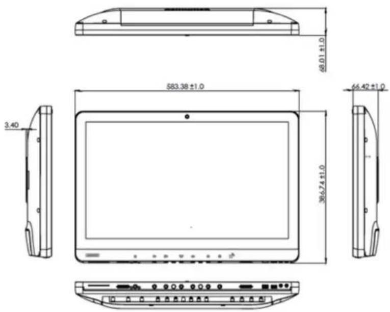
Figure 1.1 POC-624 Terminal
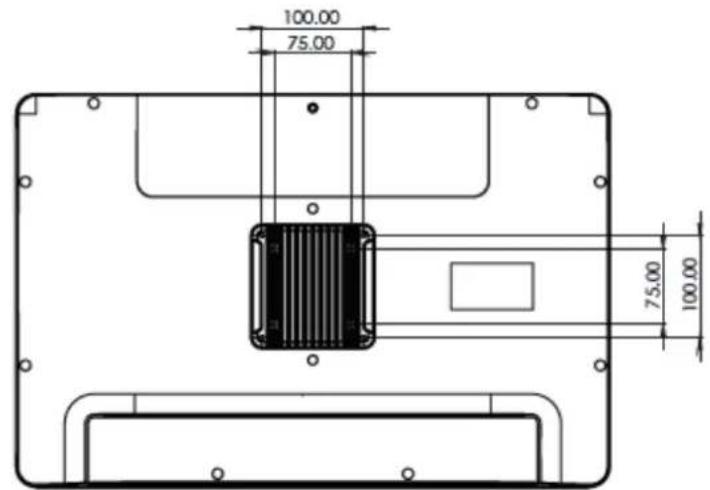
Figure 1.2 VESA Mount
VESA Mount: 75x75; 100x100
4 x M4 x 10L screws

Figure 1.3 POC-624 Front Panel
- Power 2. Volume up/down
- Touchscreen status control 4. Reading light control
- Brightness increase/decrease 6. Smart card reader
1.3.1 Optional Modules
Memory:
-2x DDR4 SODIMM (up to 32 GB)
- 2 x DDR4 SODIMM (up to 32 GB)
Primary Storage: NVME (M2 2280, PCIe Interface) 2.5" SATA SSD
Wi-Fi and Bluetooth Module: Intel® wireless-AC9260, dual-band wireless-AC 8265
RFID Module: Optional (choose either RFID or smart card reader)
Smart Card: Optional (choose either RFID or smart card reader)
Backup Battery: Optional (choose either 1 x battery or PCIe x4)
Hot-Swappable Battery Pack: Optional with 2 × batteries (choose either backup battery or hot-swappable battery module)
Camera: 1× 5 -megapixel camera (optional)
Touchscreen: Optional AR coating/AG etching
The above options may be mutually exclusive. Contact Advantech for more information.
1.3.2 Cleaning and Disinfecting
POC-624 terminals may become dirty during normal operation and thus should be cleaned regularly. Follow the steps below to clean the device.
Steps
- Prepare water for cleaning.
- Moisten a clean cloth with the water.
- Wipe the surfaces of the terminal thoroughly with the moist cloth.
Caution!

Do not immerse or rinse the POC-624 terminal or peripherals. If liquid is accidentally spilled on the device, disconnect the device from all power sources. Contact your IT support department regarding the continued safety of the unit before placing it back in operation. Do not spray cleaning agents onto the chassis. Do not use disinfectants that contain phenol. Do not autoclave or clean the POC-624 terminal or peripherals with aromatic or chlorinated solvents, ketones, ether, or ether solvents, sharp tools, or abrasives. Never immerse electrical connectors in water or other liquids.
1.4 Operating Principle
POC-624 supports data input via the touchscreen, physical keys, and accessories connected via USB or LAN/WLAN. The central processing unit processes the data and outputs the results to the LCD panel, accessories, or other devices connected via the I/O ports or LAN/WLAN. Data can be stored in the device storage. Thus, even when the device is powered off, the data is still maintained in storage memory.
1.5 Intended User Profile
Age: 18 ~ 65 years
Weight: Not relevant
Health: Not relevant
Nationality: Global
Patient state: Patient will not be the operator
Part of the body or type of tissue applied to or interacted with: Hands and fingers (expected contact time is less than 1 minute)
Education level: At least 8 years of intensive reading experience (school)
Knowledge:
- Minimum - Can read and understand westernized Arabic numerals written in Arial font
- Can distinguish every part of the body described in the user manual
- Trained and authorized by the manufacturer
To be considered trained, installation personnel must complete the training course of the manufacturer; see document number POC-624 User Manual for qualification method. When considered necessary by the manufacturer, technicians may be called back for retraining. Annual training is also considered necessary.
Language: English; when other languages are required, a professional translation company should be contracted and the resulting translation reviewed by the manufacturer.
Experience: Mentally and physically competent; specific medical training for understanding basic symbols
Permissible impairments:
- Mild reading vision impairment or vision corrected to log MAR 0,2 (6/10 or 20/32)
- At least one arm/hand capable of operating the device
Average degree of aging-related short-term memory impairment - Up to 40% hearing impairment, resulting in 60% of hearing capacity at 500 2kHz
Chapter 2
System Setup
2.1 Quick Tour
Before setting up the POC-624 terminal, take a moment to familiarize yourself with the locations and functions of the controls, drives, connectors, and ports (refer to the figures below).
When placed upright on a desktop, the POC-624 front panel should appear as shown in Figure 2.1.
2.1.1 Front View
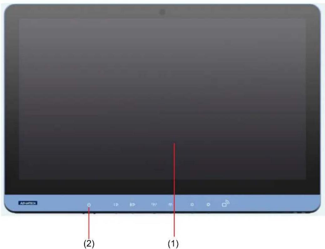
Figure 2.1 POC-624 Front View
Front View
(1) LCD panel with touchscreen
(2) Power LED indicator
2.1.2 Rear View
Located at the underside of the rear of the POC-624 terminal is the recessed I/O section, as shown in Figures 2.2 and 2.3. (The I/O section includes various I/O ports, including HDMI, Ethernet, USB, and serial ports.)
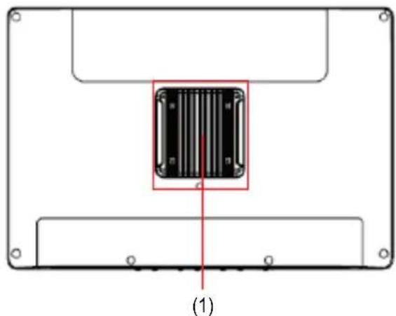
Figure 2.2 POC-624 Rear View
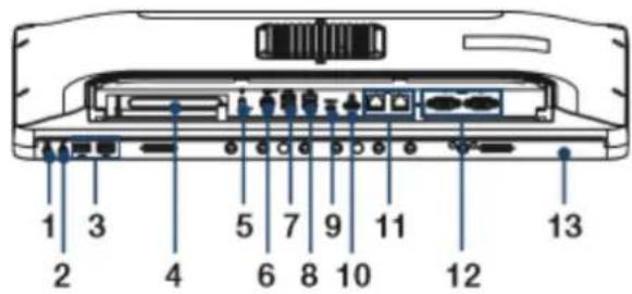
Figure 2.3 POC-624-11 Underside View
- 1 x Headphones-Out 2. 1 x Mic-In
3.2xUSB2.04.1xPCIe x4 - 1 x Equipotential terminal 6. 1 x DC-In
- 2 × USB 3.2 (Type A) 8. 2 × USB 2.0
9.2 x USB 3.2 (Type C) 10.1 x HDMI - 2 x Gigabit Ethernet 12. 2 x COM (RS-232)
- 1 x Smart card reader/ 4kV isolation board (optional)

Figure 2.4 POC-624-01 Underside View
- Headphones-Out 2. 1 x Mic-In
3.2xUSB2.04.1xPCIe x4
5.1 x Equipotential terminal 6.2 x USB 3.2 (Type A)
7.2xUSB2.08.1xUSB3.2(TypeC)
9.1 x HDMI 10.2 x Gigabit Ethernet
11.2xCOM (RS-232) 12.1xAC-In - 1 x Smart card reader/ 4kV isolation board (optional)
Note! The equipotential terminal must be linked to the hospital ground/earthing system before system boot up to protect the operator and device.

2.2 Installation Procedures
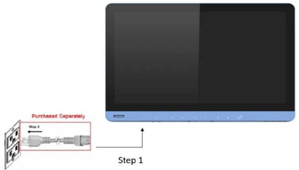
2.2.1 AC-In Power (for POC-624-01)
The POC-624-01 model should be powered by an internal AC power supply (Model Number: FSP150M-K24-18). When handling power cords, always hold them by the plug ends only.
- Connect the female end of the power cord to the AC-In port.
- Connect the 3-pin male plug of the power cord to an electrical outlet.
2.2.2 DC-In Power (for POC-624-11)
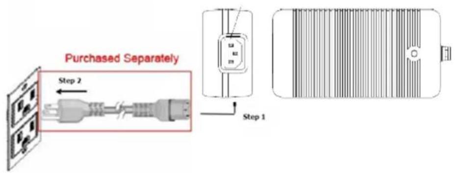
Connect the output of the AC adapter to the DC-In socket on the POC terminal.
Caution! The adapter output and DC-In plug have specific directions for use. Be sure to connect the adaptor correctly.

Warning! Connecting the wrong cable to the DC-In socket may damage the POC terminal or adapter.

2.2.3 Ground Pin Connection
An equipotential terminal is provided to facilitate connection to the ground/earthing system.
- On the underside of the POC-624 terminal, locate the equipotential terminal pin.
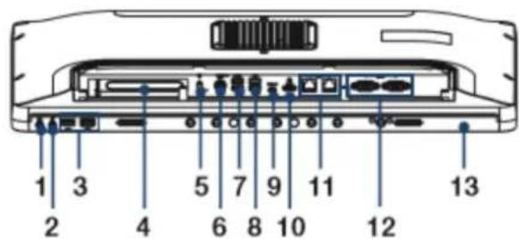
Figure 2.5 POC-624-11 Equipotential Terminal
- 1 x Headphones-Out 2. 1 x Mic-In
3.2xUSB2.04.1xPCIex4 - 1 x Equipotential terminal 6. 1 x DC-in
7.2×USB3.2(TypeA)8.2×USB2.0
9.1 x USB 3.2 (Type C) 10.1 x HDMI - 2 x Gigabit Ethernet 12. 2 x COM (RS-232)
- 1 x Smart card reader (optional)
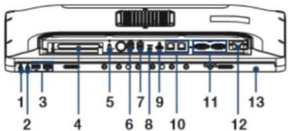
Figure 2.6 POC-624-01 Equipotential Terminal
- 1 x Headphones-Out 2. 1 x Mic-In
3.2xUSB2.04.1xPCIex4
5.1 x Equipotential terminal 6.2 x USB 3.2 (Type A)
7.2xUSB2.0 8.1xUSB3.2 (TypeC)
9.1 x HDMI 10.2 x Gigabit Ethernet - 2 x COM (RS-232) 12. 1 x AC-In
-
1 x Smart card reader (optional)
-
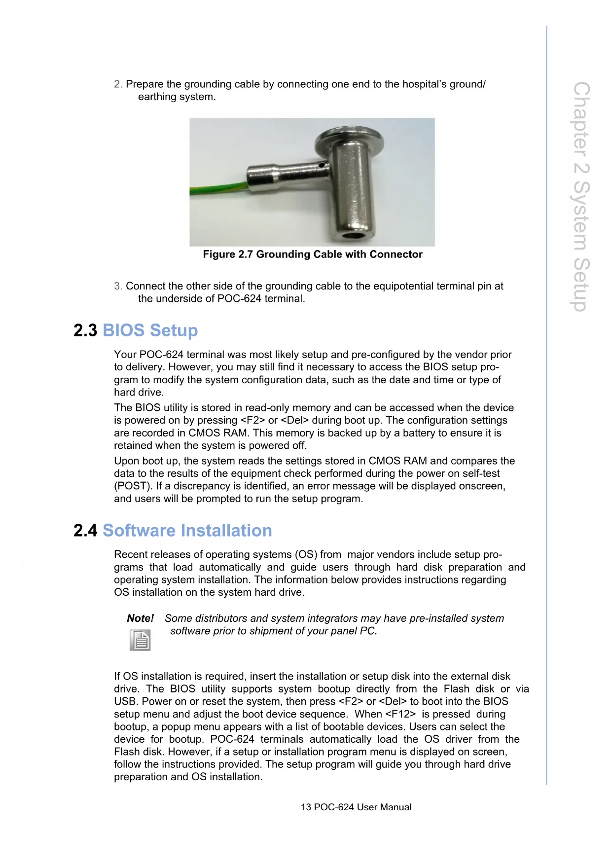
Prepare the grounding cable by connecting one end to the hospital's ground/earthing system.

Figure 2.7 Grounding Cable with Connector
- Connect the other side of the grounding cable to the equipotential terminal pin at the underside of POC-624 terminal.
2.3 BIOS Setup
Your POC-624 terminal was most likely setup and pre-configured by the vendor prior to delivery. However, you may still find it necessary to access the BIOS setup program to modify the system configuration data, such as the date and time or type of hard drive.
The BIOS utility is stored in read-only memory and can be accessed when the device is powered on by pressing <F2> or <Del> during boot up. The configuration settings are recorded in CMOS RAM. This memory is backed up by a battery to ensure it is retained when the system is powered off.
Upon boot up, the system reads the settings stored in CMOS RAM and compares the data to the results of the equipment check performed during the power on self-test (POST). If a discrepancy is identified, an error message will be displayed onscreen, and users will be prompted to run the setup program.
2.4 Software Installation
Recent releases of operating systems (OS) from major vendors include setup programs that load automatically and guide users through hard disk preparation and operating system installation. The information below provides instructions regarding OS installation on the system hard drive.
Note! Some distributors and system integrators may have pre-installed system software prior to shipment of your panel PC.

If OS installation is required, insert the installation or setup disk into the external disk drive. The BIOS utility supports system bootup directly from the Flash disk or via USB. Power on or reset the system, then press <F2> or <Del> to boot into the BIOS setup menu and adjust the boot device sequence. When <F12> is pressed during bootup, a popup menu appears with a list of bootable devices. Users can select the device for bootup. POC-624 terminals automatically load the OS driver from the Flash disk. However, if a setup or installation program menu is displayed on screen, follow the instructions provided. The setup program will guide you through hard drive preparation and OS installation.
2.5 Driver Installation
After installing the system software, users can install the chipset, graphics, Ethernet, audio, and touchscreen drivers. The standard procedures for installing the drivers are described in Chapter 5.
The various drivers and utilities on the CD-ROM disk are accompanied by text files that provide driver installation instructions and function descriptions. Those files are a useful supplement to the information provided in this manual. Additionally, all drivers can be downloaded from the Advantech website.
2.6 Troubleshooting
If the POC-624 terminal is malfunctioning or does not operate according to the user manual, reference the sections below to troubleshoot the issue.
2.6.1 Power On Failure
Pressing the power button fails to activate the device (the power indicator does not light up).
- Check that the adapter and DC-In port are properly connected.
- Check that the adapter is plugged into the DC-In port in the correct direction.
- Check that the power cord is properly plugged into the adapter.
- Check that the power cord is properly plugged into the power supply socket.
- If the device is in battery mode, check that the battery is properly installed and charged. (To check the battery capacity, remove the battery pack from the device and press the capacity indicator button.)
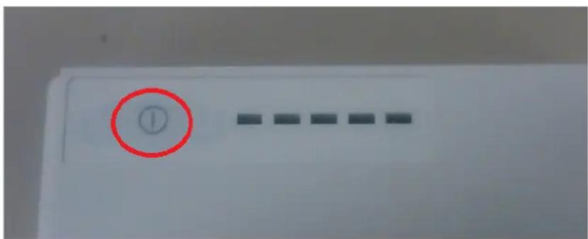
The illuminated LEDs represent the remaining battery capacity.
| State of Charge | |
| LED Green Current ()>0 | |
| LED1 0% ~ 20% | |
| LED2 0% ~ 40% | |
| LED3 0% ~ 60% | |
| LED4 0% ~ 80% | |
| LED5 0% ~ 100% |
2.6.2 Adapter Power LED Off
The power LED indicator on the adapter fails to light up.
- Check that the power cord is properly plugged into the adapter properly.
- Check that the power cord is properly plugged into the power supply socket.
2.6.3 System Fails to Boot Into Windows
The POC-624 terminal is powered on, but fails to boot into Windows.
- Check that the Windows OS is properly installed.
- Check that the BIOS boot order is properly configured. If not, configure the device boot up settings in the BIOS following the steps below.
a) After powering on the device, press "Del" to access the BIOS Utility.
b) In Boot Option #1, select "Windows Boot Manager (storage name)" and configure the settings.
c) Save changes and reset the device.
2.6.4 Power Indicator Is On But System Fails to Power On
Both the adapter power indicator and POC-624 terminal power indicator are emitting a green light, indicating that they are powered on. Yet the device fails to power on. Please contact Advantech's customer service for technical support.
2.6.5 Battery Charging Failure
- Check that the battery pack is properly installed. Push the battery pack into the battery slot to ensure that it is firmly inserted.
- Check that the adapter cable is properly connected to the DC-In port.
- The battery capacity must be less than 98% to initiate charging. This design prevents frequent overcharging. If the battery capacity exceeds this amount, the battery will not charge.
2.6.6 Technical Support
Contact your distributor, sales representative, or Advantech's customer service center for technical support if you need additional assistance. Please have the following information ready before calling:
Product name and serial number
Description of your peripheral attachments
Description of your software (operating system, version, application software, etc.)
A complete description of the problem
The exact wording of any error messages
Event logs, images, or video evidence of the symptoms (if available)
2.7 EMC Declaration
Guidance and Manufacturer's Declaration - Electromagnetic Emissions
| POC-624 series terminals are intended for use in electromagnetic environments as specified below. The customer or user of a POC-624 terminal should ensure that it is used in such an environment. | ||
| Emissions Test Compliance | Electromagnetic Environmental Guidance | |
| RF emissions CISPR 11 | Group 1 | POC-624 series terminals use RF energy only for internal function. Therefore, the RF emissions are very low and unlikely to cause interference for nearby electronic equipment. |
| RF emissions CISPR 11 | Class B | POC-624 series terminals are suitable for use in all establishments, including domestic establishments and those directly connected to the public low-voltage power supply network that supplies buildings used for domestic purposes. |
| Harmonic emissions IEC 61000-3-2 | Class D | |
| Voltage fluctuations/ flicker emissions IEC 61000-3-3 | Meets the requirements | |
Recommended Separation Distances Between Portable and Mobile RF Communications Equipment and POC-624 Series Terminals
| POC-624 series terminals are intended for use in electromagnetic environments where radi- ated RF disturbances are controlled. The customer or user of a POC-624 terminal can help prevent electromagnetic interference by maintaining a minimum distance between portable and mobile RF communications equipment (transmitters) and the POC-624 terminal, as re- ommended below, according to the maximum output power of the communications equip- ment. | |||
| Rated Maximum Output Power of Transmitter W | Separation Distance According to Frequency of Transmitter m | ||
| 150 kHz to 80 MHz d = 1,2 √p | 80 MHz to 800 MHz d = 1,2 √p | 800 MHz to 2,5 GHz d = 2,3 √p | |
| 0,01 | 0,12 | 0,12 | 0,23 |
| 0,1 | 0,38 | 0,38 | 0,73 |
| 1 | 1,2 | 1,2 | 2,3 |
| 10 | 3,8 | 3,8 | 7,3 |
| 100 | 12 | 12 | 23 |
| For transmitters rated at a maximum output power not listed above, the recom- mended separation distance d in meters (m) can be estimated using the equation in the table above applicable to the frequency of the transmitter, where P is the maxi- mum output power rating of the transmitter in watts (W) according to the transmitter manufacturer. Note 1: At 80 MHz and 800 MHz, the separation distance for the higher frequency range applies. Note 2: These guidelines may not apply in all situations. Electromagnetic propaganda is affected by absorption and reflection from structures, objects and people. | |||
Guidance and Manufacturer's Declaration - Electromagnetic Immunity
| POC-624 series terminals are intended for use in the electromagnetic environment specified below. The customer or user of a POC-624 terminal should ensure that it is used in such an environment. | |||
| Immunity Test | IEC 60601 Test Level | Compliance Level | Electromagnetic Environmental Guidance |
| Electrostatic dis-charge (ESD) IEC 61000-4-2 | ±8 KV contact ±15 kV air | ±8 kV contact ±15 kV air | Floors should be wood, concrete or ceramic tile. If floors are covered with synthetic material, the relative humidity should be at least 30%. |
| Electrical fast transient/burst IEC 61000-4-4 | ±2 KV for power supply lines ±1 KV for input/output lines | ±2 kV for power supply lines ±1 kV for input/output lines | Main power quality should be that of a typical commercial or hospital environment. |
| Surge IEC 61000-4-5 | ±1 KV line(s) to line(s) ±2 kV line(s) to earth | ±1 kV line(s) to line(s) ±2 kV line(s) to earth | Main power quality should be that of a typical commercial or hospital environment. |
| Interruptions and voltage variations on power supply input lines IEC 61000-4-11 | Voltage Dips 0% reduction for 0.5/1 cycle at 50Hz 70% reduction for 25/30 cycle at 50/60Hz Voltage Interruptions 0% reduction for 250/300 cycle at 50/60Hz | Voltage Dips 0% reduction for 0.5/1 cycle at 50Hz 70% reduction for 25/30 cycle at 50/60Hz Voltage Interruptions 0% reduction for 250/300 cycle at 50/60Hz | Main power quality should be that of a typical commercial or hospital environment. If the user of a POC-624 terminal requires continued operation during mains power interruption, we recommend powering the POC-624 terminal via an uninterruptable power supply or battery. |
| Power frequency (50/60 Hz) magnetic field IEC 61000-4-8 | 30 A/m 30 A/m | Power frequency magnetic fields should be at levels characteristic of a typical location in a typical commercial or hospital environment. | |
| Note: UT is the A.C. main voltage prior to application of the test level. | |||
Guidance and Manufacturer's Declaration - Electromagnetic Immunity
| POC-624 series terminals are intended for use in the electromagnetic environment specified below. The customer or user of a POC-624 terminal should ensure that it is used in such an environment. | |||
| Immunity test | IEC 60601 Test Level | Compliance Level | Electromagnetic Environmental Guidance |
| Conducted RF IEC 61000-4-6 | 3 and 6 Vrms150 kHz ~ 80 MHz and specific ISM, AM frequency | 3 and 6 Vrms150 kHz ~ 80 MHz and specific ISM, AM fre-quency | Portable and mobile RF communications equipment should be used no closer to any part of a POC-624 terminal, including cables, than the recommended separation distance calculated from the equation applicable to the frequency of the transmitter.Recommended Separation Distanced = 1,2√p d = 1,2 .80 ~ 800 MHzd = 2,3 .800 MHz ~ 2,5 GHz where P is the maximum output power rating of the transmitter in watts (W) according to the transmitter manufacturer and d is the recommended separation distance in meters (m). |
| Radiated RF IEC 61000-4-3 | 3V/m80 MHz ~ 2.7 GHz, and specific fre-quency | 3V/m80 MHz ~ 2.7 GHz, and specific frequency | Field strengths from fixed RF transmitters, as determined by an electromagnetic site survey, a should be less than the compliance level in each frequency range. b Interference may occur in the vicinity of equipment marked with the following symbol:((·)) |
| Note 1: At 80 MHz and 800 MHz, the higher frequency range applies.Note 2: These guidelines may not apply in all situations. Electromagnetic propagation is affected by absorption and reflection from structures, objects and people. | |||
a. Field strengths from fixed transmitters, such as base stations for radio (cellular/ cordless) telephones and land mobile radios, amateur radio, AM and FM radio broadcasts, and TV broadcasts cannot be predicted theoretically with accuracy. To assess the electromagnetic environment due to fixed RF transmitters, an electromagnetic site survey should be considered. If the measured field strength in the location in which the POC-624 terminal is used exceeds the applicable RF compliance level above, the POC-624 terminal should be observed to verify normal operation. If abnormal performance is observed, additional measures may be necessary, such as reorienting or relocating the unit.
b. Over the frequency range of 150kHz 80MHz field strengths should be less than 3V / m
Chapter 3
Operation and Safety
3.1 General Safety Guide
To ensure user safety and prevent equipment damage, always disconnect the power (by pulling the plug, not the cord) and remove the battery pack from the POC terminal in the following situations:
The power cord or plug is frayed or otherwise damaged.
Any substance is spilled onto the POC terminal.
The POC terminal has been dropped or the case has been damaged.
The POC terminal needs servicing or repair.
The POC terminal needs to be cleaned.
Any internal parts need to be installed or removed (excluding the hot-swappable battery pack).
3.2 Hot-Swappable Battery Module
To ensure convenient operation, POC-624 series terminals also support an optional hot-swappable battery module (Part Number: POC-624-BAT-201-62), in which two battery packs can be installed.
3.3 Battery Pack Installation
- Locate the blue doors (circled in red below) on either side of the battery module at the rear of the POC terminal.
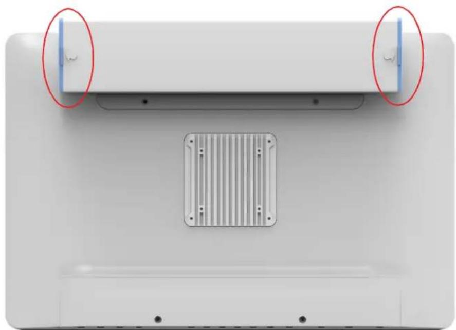
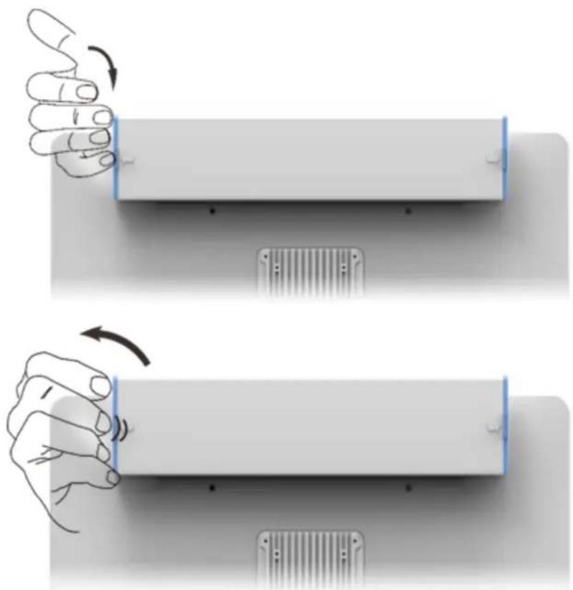
- Locate the arrow push buttons next to the blue doors.
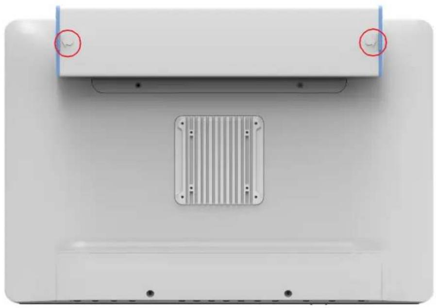
- Press the arrow push buttons and pull open the doors to access the battery module slot.
- Insert the battery pack into the battery module. The module opening and battery packs feature notches (circled in red below) that indicate the correct installation direction.

Caution! We recommend holding the battery pack with both hands when installing it into the battery module.

- Close the battery module door and press firmly until an audible "click" is heard to ensure that the door is securely closed.
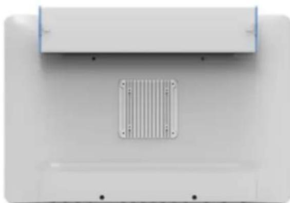
Warning! If the module doors are not securely closed, the battery may fall out.

Ensure that the mylar and pull ring (indicated in the image below) are returned to their original position (flat against the battery) before closing the door.

The POC-624 terminal cover features vent holes that function as air inlets and outlets that transfer heat from inside the equipment to the cooler air outside. Do not block the holes/vents with any material.
During operation, it is normal for the metal heatsink at the rear of the device to become warm. The metal heatsink functions as a cooling surface that transfers heat from inside the equipment to the cooler air outside. Do not block the heatsink with any material.
To protect the battery pack from overheating, use/charge the battery in accordance with the instructions provided in this user manual.
Warning!

3.5 Disconnect the Power
The only way to disconnect the power completely is to unplug the power cable. When using the device, ensure that at least one end of the power cable is within easy reach to allow for unplugging if necessary.
Warning!
The AC power cable is equipped with a 3-wire grounding plug (the plug has a third grounding pin). This plug will only fit a grounded AC outlet. If you are unable to insert the plug into an outlet because the outlet is not grounded, contact a licensed electrician to replace the outlet with a properly grounded outlet. Do not try to get around this or you will defeat the purpose of the grounding plug.

Warning! Never push objects through the openings in the case into the device as this may cause fire or electric shock.

Never place anything on the case before powering off the device.
Never power on the device if any of the internal or external parts have been removed. Operating the device when open or missing parts can be dangerous and may damage your computer.
Handle the POC terminal with care. The device is made of metal, glass, and plastic and contains sensitive electronic components. Because the POC-624 terminal is heavy, we recommend using both hands when carrying the device. We also recommend using both hands when installing, removing, or replacing a battery pack.
Warning! Do not attempt to use the POC-624 terminal if it is damaged (for example, the case is cracked or broken) as this may cause injury.

Caution! 1. Setup and install the POC-624 terminal on a stable surface.
Read all safety instructions and warnings before using or charging the battery.
Warning! Li-ion battery packs may explode and cause fire if defective or used incorrectly. To prevent this from happening, follow all usage instructions and safety guidelines provided in this user manual.
Caution! 1. Removal of the battery pack and unplugging of the power adapter will cause the POC-624 terminal to shut down, which may result in data losses. To prevent data losses, always save your work and shut down the POC-624 terminal before removing the battery or power adapter.
- The POC terminal should only be powered by an Advantech battery pack or compatible battery pack supplied by Advantech.
Warning! 1. Do not insert non-Advantech battery packs into the POC terminal.

- Do not attempt to use battery packs of a different brand.
- N'insérez pas de blocs-batteries non Advantech dans le système POC.
-
N'essayez pas d'utiliser des batteries d'une marque différente.
-
Be careful not to make the wrong polarity connection when charging and using battery packs. Always double check the battery installation direction before insertion or connection with the charger.
Warning! Batteries installed in the wrong direction with the opposite polarity are at risk of exploding, which may cause fire.
- Use only the specific li-ion battery charger provided by Advantech to charge the battery pack.
Warning! Using a battery charger of a different brand may cause the battery to explode and result in fire.
- Do not short the battery pack connector by using a wire lead.
Warning! Wire lead shorts can cause the battery to explode and result in fire.
- Do not drop the battery pack.
Warning! If the battery cover is cracked, split, or broken, do not use the battery
- Do not expose the battery pack to fire or high temperatures.
Warning! Exposure to high temperatures may cause the battery to explode.
- Do not penetrate the battery with nails, strike the battery with a hammer, step on the battery, or otherwise subject it to significant impact or shock.
Warning! Batteries are at risk of exploding and may cause fire if subjected to significant impact.

-
Do not expose the battery pack to moisture or water.
-
Do not disassemble or modify the battery pack. The battery pack contains safety and protection circuits that if damaged, may cause the battery to overheat, explode, or ignite. There are no user-serviceable parts inside the battery pack.
- Always refer to the battery charger user manual for charging instructions.
- Charge the battery pack in indoor environments with a controlled temperature.
Caution!
Exposure to extreme temperatures can damage the battery and reduce the battery life capacity.

- Do not leave fully charged battery packs connected to the charger for prolonged periods of time.
Caution!
When the battery is fully recharged, disconnect it from the charger or unplug the charger power cable.

- Do not discharge the battery pack using any device other than the POC terminal or a device specified by Advantech.
Warning!
Using the battery pack to power devices other than the POC-624 terminal may damage the battery, limit performance, or reduce the battery capacity. Additionally, exposure to abnormal current may cause the battery pack to overheat, explode, or ignite and cause serious injury.

- Use/discharge the battery pack in indoor environments where the temperature is controlled.
Caution!
Using the battery in environments with temperatures outside the acceptable range may damage the battery, limit performance, or reduce the battery capacity.

- Inspect all battery packs before use.
Waming!
- Never use battery packs that are visibly damaged or that may be internally damaged.
- Never remove a battery cover or use a battery pack with a damaged cover.
- N'utilisez jamais de blocs-piles visiblement endommages ou dommages internes.
-
Ne retirez jamais le couvercle extérieur de la batterie et n'utilise jamais de batterie avec un couverture endommagée.
-
Replace the entire battery pack with a new battery pack when the time between charges decreases significantly.
Caution!
When the time between charges decreases significantly, check the voltage of the battery pack before charging. If the battery performance drop significantly, do not use the battery pack.
If you notice any of the following, stop charging or using the battery immediately:
- The battery is swollen, bulging, or deformed.
- The battery is leaking fluid, smoke, or a foul odor.
- The battery temperature is extremely hot.
- The battery appears abnormal in any way.
- The battery cover is cracked, split, or broken.
- The battery has been exposed to moisture.
Warning!
3.10 Battery Storage and Transportation
- Store the battery in a dry environment with a room temperature of 0 25^ C (32 77^ F ) for optimum health.
- Do not expose the battery pack to direct sunlight (heat) or store the battery pack inside vehicles in hot weather for extended periods.
- When transporting or temporarily storing the battery in a vehicle, the internal vehicle temperature should be greater than -20^ (-4^) but no more than 50 ^ C (122^) .
- If possible, remove the battery pack from the device if the device will be unused for several months.
- Do not remove individual battery packs from the original packaging until required for use.
Warning!
To reduce the risk of damage, do not expose battery packs to high temperatures for extended periods of time. This may damage the battery and cause fire.

3.11 Battery Disposal
When the battery pack has reached the end of its service life, do not use general household waste for disposal. Follow local laws and government regulations for correct battery disposal.
Caution! Cover terminals with tape to prevent inadvertent contact with other batteries or metal objects.
Warning! 1. To reduce the risk of fire or burns, do not disassemble, crush, puncture, expose to fire or water, or short the battery's external contacts.
4.1 VESA Mount Installation
The POC-624 series terminals support VESA mounting, allowing system integrators to conveniently integrate the device into various computing infrastructures. To prevent unreliable and dangerous mounting, only use mount brackets provided by Advantech. Additionally, we recommend that mount installation be conducted by a qualified service technician according to the instructions provided below.
- Attach the wall mount to the heatsink of the POC terminal, securing it in place with the four Phillips-head screws provided.
- Mount the unit onto a wall, stand, or other flat surface.
Warning!
Secure the screws of the mount bracket tightly. A loose joint between the POC-624 terminal and mount bracket may cause the device to fall and result in injury.

The POC-624 series terminals support the Windows 10 IoT (64 bit), RS5 version or later, operating system. However, the 32-bit driver is no longer supported.
Warning!
Conduct a clean installation of the OS before installing the drivers to avoid unexpected errors.

Install the correct drivers that are compatible with the OS version you are using. Drivers should be installed according to the order listed below.
| Installation Order | Folder Name Note | |
| 1 Chipset Install the chipset driver first. | ||
| 2 Graphics | Because the Intel Graphics Command Center (IGCC) is no longer combined with the driver, after installing the graphics driver, install IGCC from PowerShell. | |
| 3 Audio | ||
| 4 LAN | ||
| 5 AMT Intel Management Engine Driver | ||
| 6 RST Intel Rapid Storage Technology | ||
| 7 | Wireless Card (Wi-Fi + Bluetooth) | Optional |
| 8 RFID | Optional | |
| 9 Smart Card | Optional | |
Chapter 6
PCM-8722 Connector Map
The POC-624 series terminals feature a PCM-8722 printed circuit board assembly.
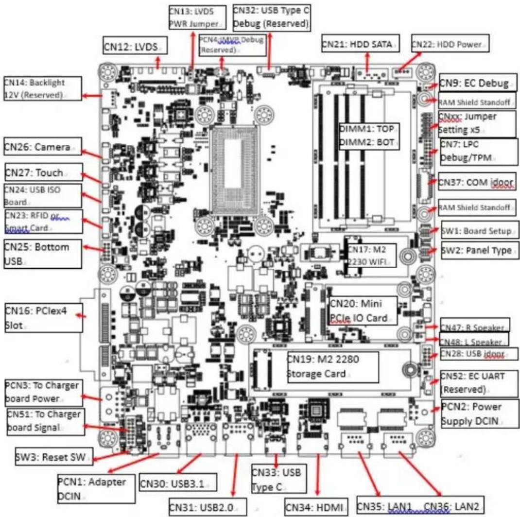
Figure 6.1 Motherboard Top Side View
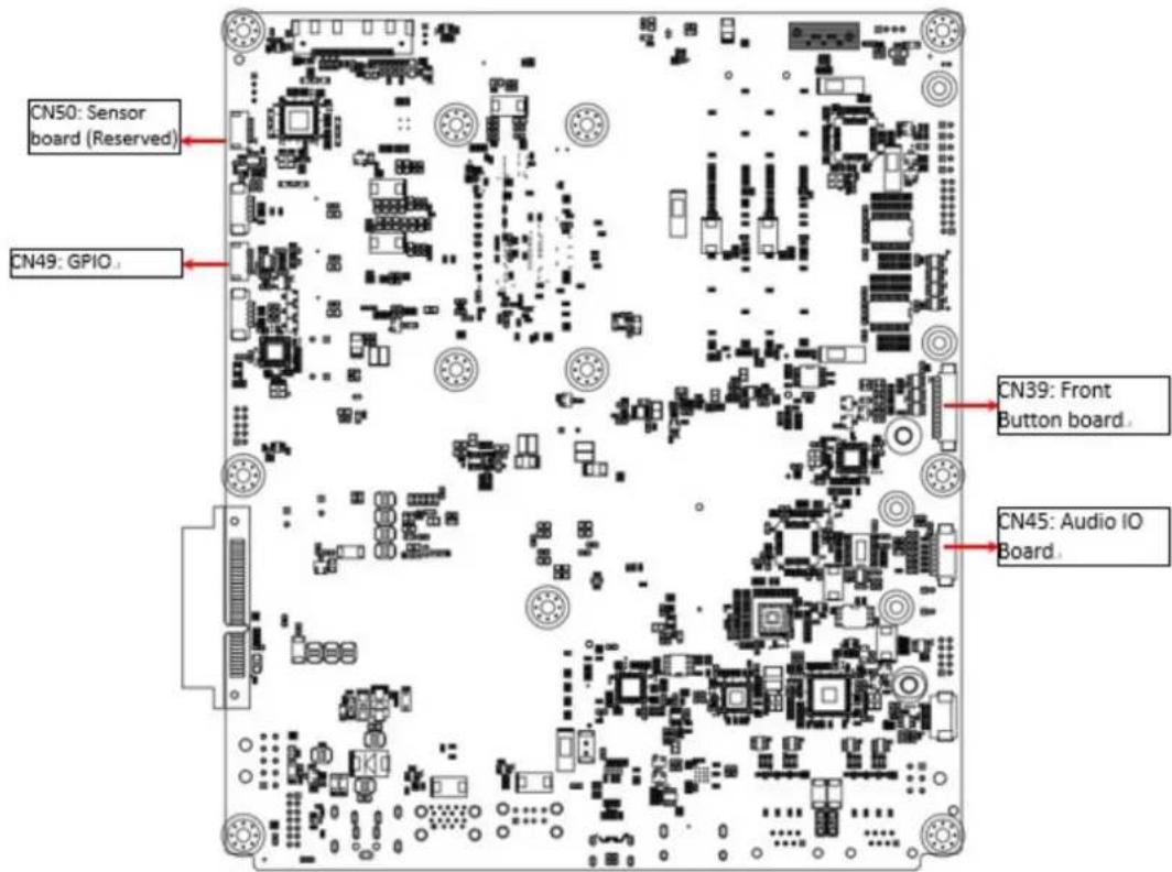
Figure 6.2 Motherboard Bottom Side View
Chapter 7
PCM-8722 Jumper Settings
The POC-624 series terminals feature a PCM-8722 printed circuit board assembly. All jumpers and DIP switches are located on the top side of the motherboard.
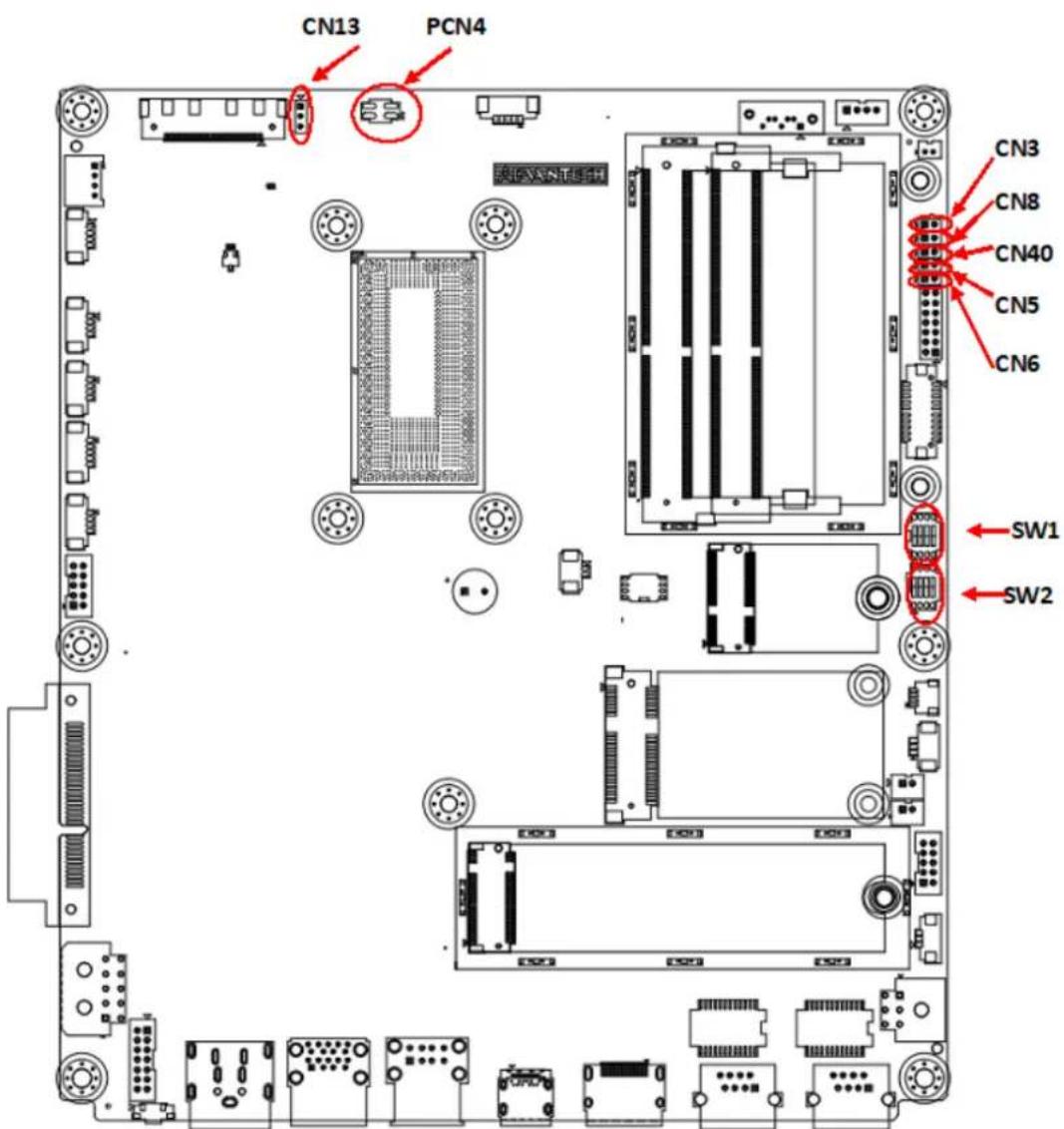
Figure 7.1 Motherboard Top Side
Jumper Settings
CN3 ME Manufacturing Mode
CN5 Clear CMOS
CN6 Clear ME (reserved, not installed)
CN8 System Reset (reserved, not installed)
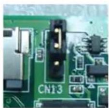
CN13 LVDS Voltage
CN40 Power Button (reserved, internal test only)
PCN4 Power Debug (reserved)
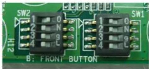
SW1 Board Setup
SW2 Panel Setup
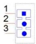
CN3 ME Manufacturing Mode
Description ME manufacturing mode
Setting Function
(1-2) ME manufacturing mode
Not connected) Normal operation (default)
CN5 Clear CMOS
Description Clear CMOS setup
Setting Function
(1-2) Clear CMOS setup
Not connected) Normal operation (default)
CN6 (Not Installed) Clear ME
Description Clear ME setup
Setting Function
(1-2) Clear ME setup
Not connected) Normal operation (default)

CN8 (Not Installed) System Reset
Description Reset system button
Setting Function
(1-2) System reset
Not connected) Normal operation (default)
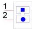
CN13 LVDS Voltage Setup
Description Select panel LVDS voltage setting
Setting Function
(1-2) Panel LVDS voltage 5V (default)
(2-3) Panel LVDS voltage 3.3V
CN40 Power Button (Internal Test Only)
Description Power button signal
Setting Function
(Pin 2) Short pin 1 to power on
Not connected) Normal operation (default)

PCN4 Power Debug (Reserved)
Description Power debug, internal test only
Setting Function
Not connected) Normal operation (default)

SW1 Board Setup
Description Select board setting
Setting Function
(SW1-1/2/3) Select board type
(SW1-4) Force speaker always on

SW1 Pin 1 SW1 Pin 2 SW1 Pin 3 Board Configuration
High (Off) High (Off) High (Off) Board Config 1 (default)
High (Off) High (Off) Low (On) Board Config 2
High (Off) Low (On) High (Off) Board Config 3
High (Off) High (Off) High (Off) Board Config 4
Low (On) High (Off) High (Off) Board Config 5
Low (On) High (Off) Low (On) Board Config 6
Low (On) Low (On) High (Off) Board Config 7
Low (On) High (Off) High (Off) Board Config 8
SW1 Pin 4 Speaker Function
High (Off) Speaker mute when audio plug in - with audio board system (default)
Low (On) Speaker always on - without audio board system (default)
SW2 Panel Resolution/Type Setup
Description Select panel setting
Setting Function
(SW2-1~4) Select panel type

| SW2 Pin 1 | SW2 Pin 2 | SW2 Pin 3 | SW2 Pin 4 | Panel Resolution | LVDS Channel |
| High (Off) | High (Off) | High (Off) | High (Off) | 1920x1200 | 24 bits dual |
| Low (On) | High (Off) | High (Off) | High (Off) | 1920x1080 (default) | 24 bits dual |
| High (Off) | High (Off) | Low (On) | High (Off) | 1600x900 | 24 bits dual |
| Low (On) | Low (On) | Low (On) | High (Off) | 1366x768 | 24 bits single |
| Low (On) | High (Off) | High (Off) | Low (On) | 1280x1024 | 24 bits dual |
| Low (On) | High (Off) | Low (On) | Low (On) | 1024x768 | 24 bits single |
| Low (On) | Low (On) | Low (On) | Low (On) | 800x600 | 18 bits single |
Different System Summary
POC-624 terminal
POC-624, without audio board, 5V LVDS panel
SW1 Pin 1 SW1 Pin 2 SW1 Pin 3 SW1 Pin 4 SW2 Pin 1 SW2 Pin 2 SW2 Pin 3 SW2 Pin 4 CN13
High (Off) High (Off) High (Off) High (Off) Low (On) High (Off) High (Off) High (Off) (1-2)
Chapter 8
Front Panel Buttons
8.1 Front Panel Function Buttons


Button Description
Power Button
Press this button to power on/off the device. When the device is on, this icon will emit green light. When the device is off, the LED indicator will be off.
Reduce Volume (
Press this button to reduce speaker and headphone volume.
Increase Volume
Press this button to increase speaker and headphone volume.
Disable Touch Function

Press this button to disable/enable touch function. When touch function is enabled, this icon will emit green light. When touch function is disabled, the LED indicator will be off.
Reading Light

Press this button to enable/disable the reading light.
Reduce Brightness

Press this button to reduce the LCD backlight brightness.
Increase Brightness

Press this button to increase the LCD backlight brightness.
Additional Functions
Press and hold both the reduce brightness and increase brightness buttons for half a second to turn off/on the LCD backlight.
Turning the backlight off will not impact any program or the operation of the POC-624 terminal.
The backlight off function is useful for hospital and dark room environments because it allows users to quickly turn off the backlight without affecting the system operation. After a system restart, the backlight will automatically resume on status.
Chapter 9
Advanced BIOS Function
9.1 Additional BIOS Utility Functions
1. Power Button Function
Users can enable/disable power button function in the BIOS utility. If the power button function is disabled when the device is in S0 (System On) status, the user will not be able to power off the device using the power button. Instead, the user will need to power off the device via software. This can prevent unexpected shutdowns caused by accidentally touching the power button.
BIOS Location
BIOS Menu – Advanced – IT5121 HW Monitor – Power Button Function Enable: The power button function is enabled when in S0 (System On) status (default).
Disable: The power button function is disabled when in S0 (System On) status. Because disabling the power button function means the system will not power on when the power button is pressed, when this function is disabled, the BIOS will set the "State After G3" to "Power On" automatically. Thus, the system can be powered on by plugging in the power adapter.
2. Brightness Button Function
Users can enable/disable the LCD backlight button function in the BIOS utility. If the LCD backlight button function is disabled, users will not be able to adjust the LCD backlight luminance using this button. This can prevent unexpected changes in LCD backlight luminance caused by accidentally touching the LCD backlight button.
BIOS Location
BIOS Menu - Advanced - IT5121 HW Monitor - Brightness Button Control Enable: The LCD backlight button function is enabled (default).
Disable: The LCD backlight button function is disabled.
3. Volume Button Function
Users can enable/disable the front volume button function in the BIOS utility. If the volume button function is disabled, users will not be able to adjust the volume using this button. This can prevent unexpected changes in volume caused by accidentally touching the volume button.
BIOS Location
BIOS Menu - Advanced - IT5121 HW Monitor - Volume Button Control Enable: The volume button function is enabled (default).
Disable: The volume button function is disabled.
4. Touch Button Function
Users can enable/disable the touch button function in the BIOS utility.
If the touch control button function is disabled, users will not be able to use this button to turn off touch control. Thus, the touch function will be always on.
BIOS Location
BIOS Menu - Advanced - IT5121 HW Monitor - Touch Button Control Enable: The touch control button function is enabled (default).
Disable: The touch control button function is disabled.
5. Reading Light Button Function
Users can enable/disable the reading light button function in the BIOS utility. If the reading light button function is disabled, users will not be able to turn on the reading light using this button. Thus, the reading light function will be always off.
BIOS Location
BIOS Menu - Advanced - IT5121 HW Monitor - Read Light Control
Enable: The reading light button function is enabled (default).
Disable: The reading light button function is disabled.
6. EC Beep Function
Users can enable/disable the EC beep function in the BIOS utility.
If the EC beep function is disabled, no sound will be emitted when a front panel function button is pressed.
BIOS Location
BIOS Menu - Advanced - IT5121 HW Monitor - Beep Sound Function
Enable: When a front panel function button is pressed (default), a beeping sound is emitted.
Disable: No sound is emitted when a front panel function button is pressed.
7. Setup Popup Menu F12
Users can setup the popup menu during system bootup by pressing F12.
When F12 is pressed during bootup, the BIOS utility will display a bootable device menu. Users can select the device to bootup.
www.advantech.com
Please verify specifications before quoting. This guide is intended for reference purposes only.
All product specifications are subject to change without notice.
No part of this publication may be reproduced in any form or by any means, such as electronically, by photocopying, recording, or otherwise, without prior written permission from the publisher.
All brand and product names are trademarks or registered trademarks of their respective companies.
© Advantech Co., Ltd. 2021