
KSET650X - Basket SMEG - Free user manual and instructions
Find the device manual for free KSET650X SMEG in PDF.
| Product type | Built-in kitchen hood |
| Brand | Smeg |
| Model | KSET650X |
| Use | Extracting version (external venting) or recirculating version (recycling with activated charcoal filter) |
| Power supply | 220-240 V ~ 50/60 Hz |
| Suction power | 3 speeds + intensive speed P (5 minutes) |
| Lighting | Halogen lamp 12V 20W (GU4) or incandescent 40W max (E14) or PL 9W/11W (G23) depending on version |
| Grease filter | Metallic, dishwasher safe (monthly cleaning) |
| Activated charcoal filter | Optional, replacement every 6 months |
| Timer | Yes: 20 min (speed 1), 15 min (speed 2), 10 min (speed 3), 5 min (intensive speed) |
| Control | Electronic touch panel with LED display and filter saturation indicators |
| Minimum installation distance | 43 cm (electric cooking) / 65 cm (gas or mixed cooking) |
| Installation | Built into a cabinet or wall mounting (depending on model) |
| Safety | Automatic shut-off when closing the drawer; unplug before maintenance |
| Cleaning | Exterior: damp cloth with denatured alcohol or neutral detergent |
| Reparability | Spare parts available: filters, lamps (halogen, incandescent, PL) |
Frequently Asked Questions - KSET650X SMEG
User questions about KSET650X SMEG
0 question about this device. Answer the ones you know or ask your own.
Ask a new question about this device
Download the instructions for your Basket in PDF format for free! Find your manual KSET650X - SMEG and take your electronic device back in hand. On this page are published all the documents necessary for the use of your device. KSET650X by SMEG.
USER MANUAL KSET650X SMEG
natural_image
Line drawing of a laptop computer case with open panel and internal components (no text or symbols)GB Instruction on mounting and use
1
Rückseite
Rear side
côté postérieur
Achterzijde
Lato posteriore
Parte posterior
Lado traseiro
Видсзади
Οπισθιαπλευρα
Τγή
Ηάτβαί
Vorderseite Frontal side côté antérieur Voorzijde Lato anteriore Parte anterior Lado dianteiro Видспереди Мпростотулесора Przód Homlokdal
Vorderseite Frontal side côté antérieur Voorzijde Lato anteriore Parte anterior Lado dianteiro Видспереди Мпроотиплеура ato Przód Homlokfal

natural_image
Technical line drawing of a table with legs and feet, showing structural supports and a flat top (no text or symbols)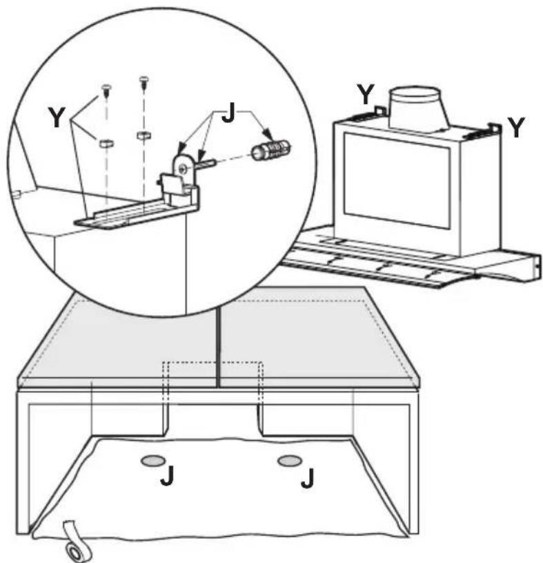
4.14.
5
6
9
natural_image
Technical line drawing of a mechanical device with a triangular pointer labeled 'S' (no text or symbols beyond the label)Consult the designs in the front pages referenced in the text by alphabet letters. Closely follow the instructions set out in this manual. All responsibility, for any eventual inconveniences, damages or fires caused by not complying with the instructions in this manual, is declined.
Description of the hood - Fig. 1
1 Control panel
2 Grease filter
3 Grease filter release handle
4 Halogen lamp
5 Vapour screen
6 Vapour screen guides
7 Air exit
8 Fairing (supplied in two sizes)
9 Fixing points for cabinet
10 Inspection door for the suction group (ACCESS ALLOWED ONLY BY A QUALIFIED TECHNICIAN)
Installation - Fig. 5-6
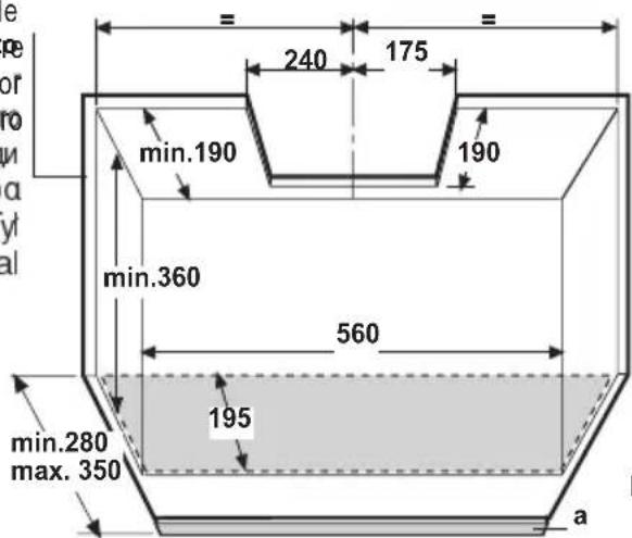
The cooker hood must be placed at a minimum distance of 43 cm from the cooking plane for electric cookers and 65cm for gas or mixed cookers.
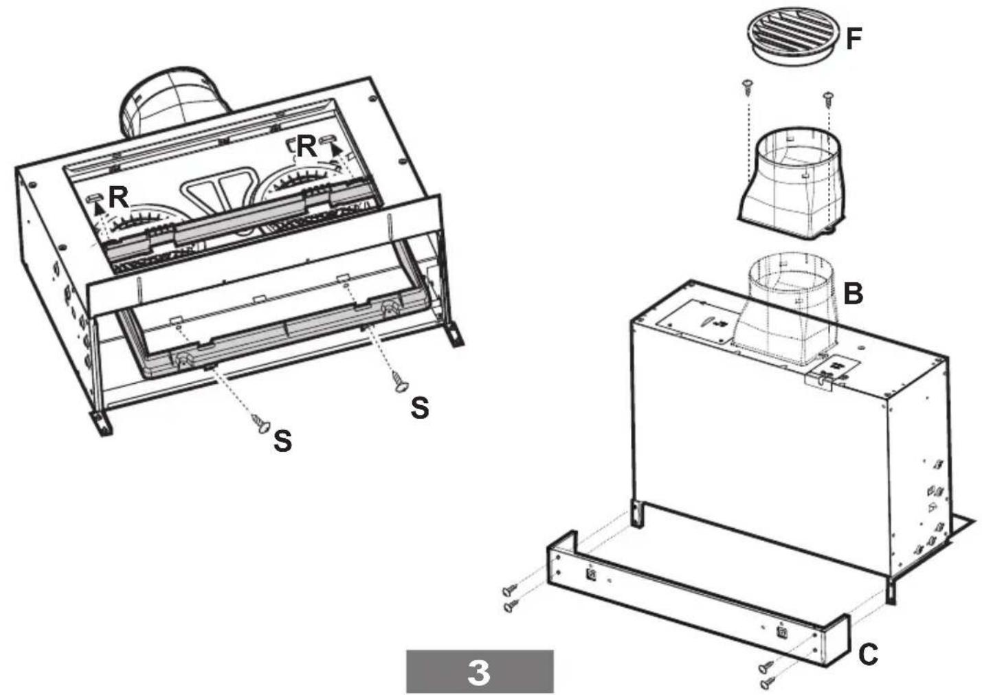
The hood is equipped with a top air outlet B for discharge of fumes to the outside (Ducting version – exhaust pipe and pipe fixing clamps not provided).
Where it is not possible to discharge cooking fumes and vapours externally, the cooker hood may be used in the filter version by mounting an active carbon filter and the deflector F on the connection ring placed on the exit perforation B (Fig. 3), the fumes and vapours are recycled via the deflector.
The models with no suction motor only operate in ducting mode, and must be connected to an external suction device (not supplied).
Preliminary information for installation of the hood: Disconnect the cooker hood from the electrical mains during the electrical connection phase.
The cooker hood is designed for installation inside a wall cabinet.
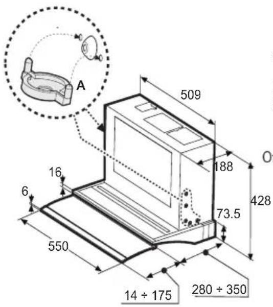
It is recommended to install the cooker hood only inside a cabinet of suitable dimensions.
Do not tile, grout or silicone this appliance to the wall. Surface mounting only.
Do not fix chimney flue to furniture or fly over shelves unless the chimney flue can be easily removed, in case maintenance is ever required.
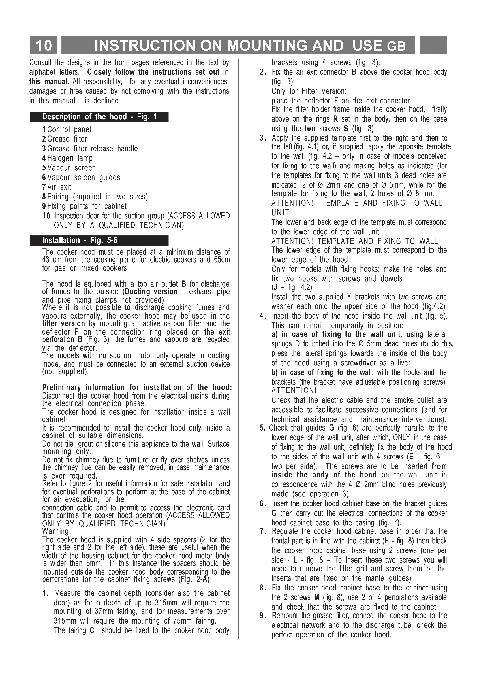
Refer to figure 2 for useful information for safe installation and for eventual perforations to perform at the base of the cabinet for air evacuation, for the
connection cable and to permit to access the electronic card that controls the cooker hood operation (ACCESS ALLOWED ONLY BY QUALIFIED TECHNICIAN).
Warning!
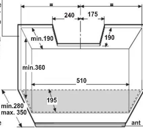
The cooker hood is supplied with 4 side spacers (2 for the right side and 2 for the left side), these are useful when the width of the housing cabinet for the cooker hood motor body is wider than 6mm. In this instance the spacers should be mounted outside the cooker hood body corresponding to the perforations for the cabinet fixing screws (Fig. 2-A)
- Measure the cabinet depth (consider also the cabinet door) as for a depth of up to 315mm will require the mounting of 37mm fairing, and for measurements over 315mm will require the mounting of 75mm fairing.
The fairing C should be fixed to the cooker hood body
brackets using 4 screws (fig. 3).
- Fix the air exit connector B above the cooker hood body (fig. 3).
Only for Filter Version:
place the deflector F on the exit connector.
Fix the filter holder frame inside the cooker hood, firstly above on the rings R set in the body, then on the base using the two screws S (fig. 3).
- Apply the supplied template first to the right and then to the left (fig. 4.1) or, if supplied, apply the apposite template to the wall (fig. 4.2 – only in case of models conceived for fixing to the wall) and making holes as indicated (for the templates for fixing to the wall units 3 dead holes are indicated, 2 of ∅ 2mm and one of ∅ 5mm, while for the template for fixing to the wall, 2 holes of ∅ 8mm).
ATTENTION! TEMPLATE AND FIXING TO WALL UNIT
The lower and back edge of the template must correspond to the lower edge of the wall unit.
ATTENTION! TEMPLATE AND FIXING TO WALL
The lower edge of the template must correspond to the lower edge of the hood.
Only for models with fixing hooks: make the holes and fix two hooks with screws and dowels (J - fig. 4.2).
Install the two supplied Y brackets with two screws and washer each onto the upper side of the hood (fig.4.2).
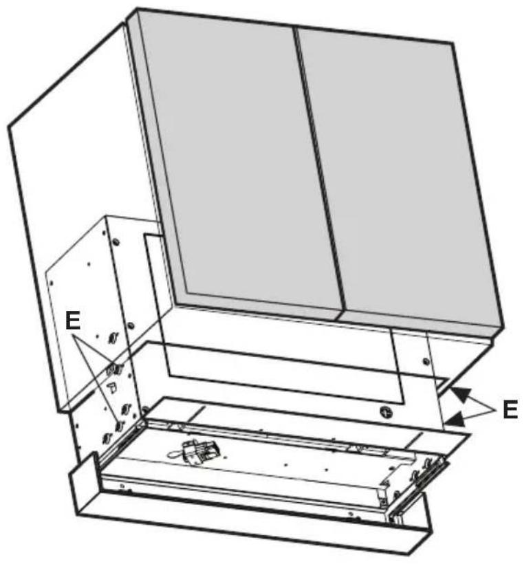
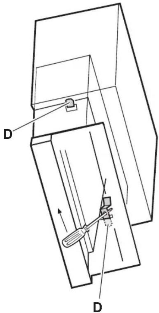
- Insert the body of the hood inside the wall unit (fig. 5). This can remain temporarily in position:
a) in case of fixing to the wall unit, using lateral springs D to imbed into the ∅ 5mm dead holes (to do this, press the lateral springs towards the inside of the body of the hood using a screwdriver as a liver.
b) in case of fixing to the wall, with the hooks and the brackets (the bracket have adjustable positioning screws). ATTENTION!
Check that the electric cable and the smoke outlet are accessible to facilitate successive connections (and for technical assistance and maintenance interventions).
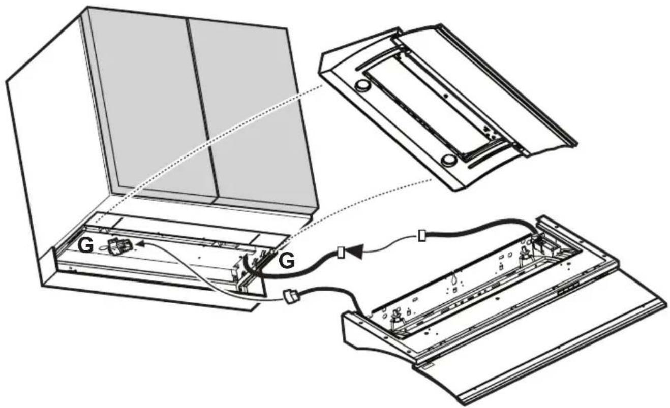
5. Check that guides G (fig. 6) are perfectly parallel to the lower edge of the wall unit, after which, ONLY in the case of fixing to the wall unit, definitely fix the body of the hood to the sides of the wall unit with 4 screws (E - fig. 6 - two per side). The screws are to be inserted from inside the body of the hood on the wall unit in correspondence with the 4 ∅ 2mm blind holes previously made (see operation 3).
6. Insert the cooker hood cabinet base on the bracket guides G then carry out the electrical connections of the cooker hood cabinet base to the casing (fig. 7).
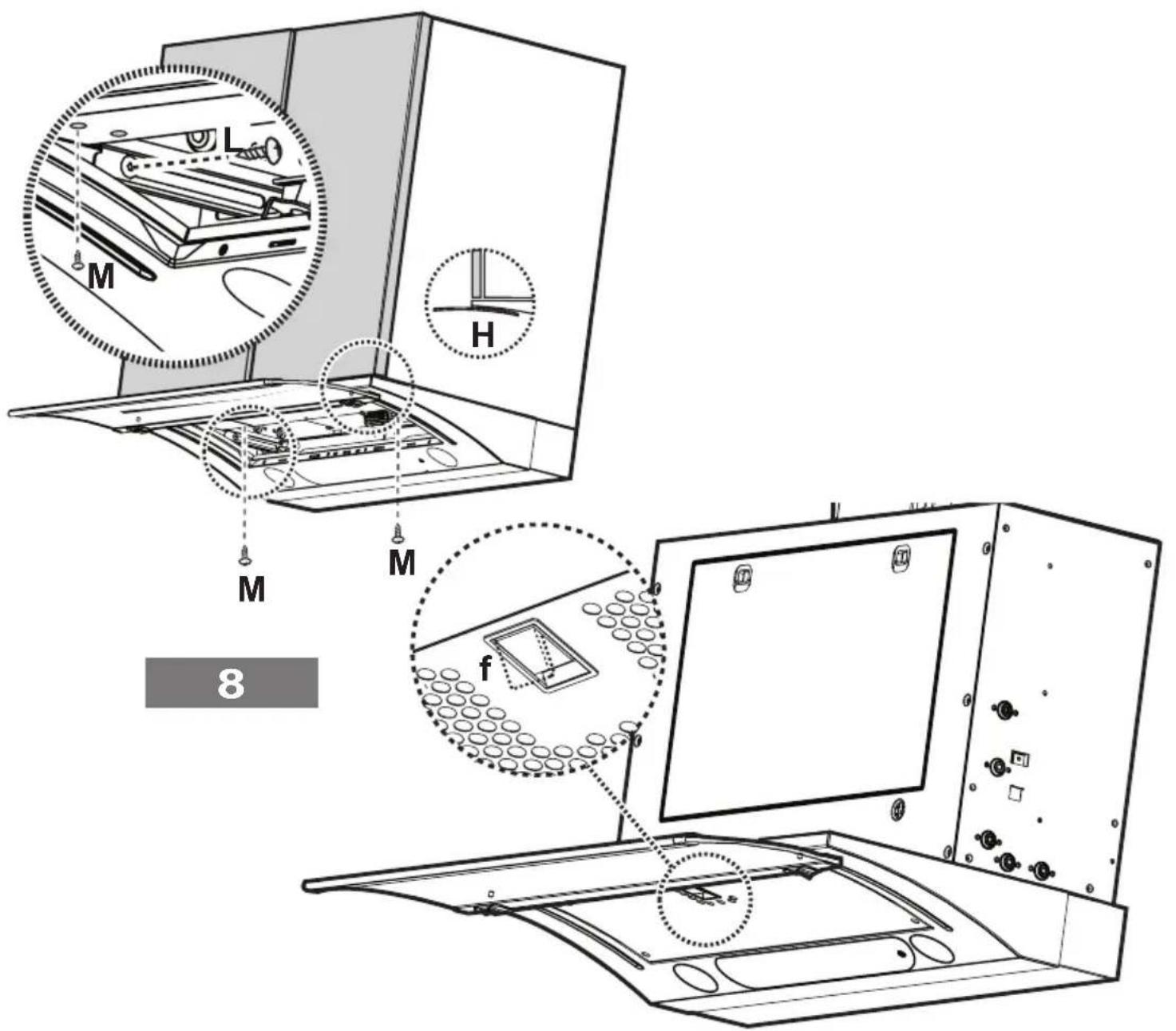
7. Regulate the cooker hood cabinet base in order that the frontal part is in line with the cabinet (H - fig. 8) then block the cooker hood cabinet base using 2 screws (one per side - L - fig. 8 - To insert these two screws you will need to remove the filter grill and screw them on the inserts that are fixed on the mantel guides).
8. Fix the cooker hood cabinet base to the cabinet using the 2 screws M (fig. 8), use 2 of 4 perforations available and check that the screws are fixed to the cabinet.
9. Remount the grease filter, connect the cooker hood to the electrical network and to the discharge tube, check the perfect operation of the cooker hood.
GB INSTRUCTION ON MOUNTING AND USE11
Electrical connection
The electrical tension must correspond to the tension noted on the label placed inside the cooker hood. Connect the electrical plug, where provided, to the an easily accessible outlet in conformity with local standards in force.
Where an electrical plug is not provided (for direct connection to electrical network) place a standards approved bipolar switch with an aperture distance of not less than 3mm (accessible) from the contacts.
Operation – Model with electronic controls
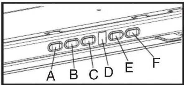
A - Lighting, on/off.
B - Fan off (Stand by)
C - Timer for selected speed (visualizes the speed selected and flashing LED on the lower side of the display).
This knob permits the operation of the cooker hood for a established period:
20 minutes if the speed selected is 1
15 minutes if the speed selected is 2
10 minutes if the speed selected is 3
5 minutes if the intensive speed P is selected.
D - Display showing fan speed (1-3-P), change grease filters (grease filter saturation indicator - F) and change activated carbon filters (carbon filter saturation indicator - C).
When the led in the lower right side is on, it indicates that the cooker hood is ready for operation ("standby" position), the flashing LED indicates that the timer has been activated for selected speed.
Warning!
The active carbon filter saturation function is not activated. In order to activate the carbon filter saturation indicator press buttons E and F simultaneously for 3 seconds. Initially, only letter F will fbe displayed, then after the 3 seconds have passed, letter C will be displayed as well, indicating that the carbon filter saturation control system is active.
To switch off the system, re-press the same two buttons: letter C appear on display and after 3 seconds letter it disappear and the device will be switched off.
E - Knob to decrease the speed: from intensive speed P to speed level 1.
F - Knob to increase (standby) speed to intensive speed P.
Attention! Intensive speed P has a duration of 5 minutes after which the cooker hood automatically sets the speed to level 2 (suction power).
If the hood fails to operate correctly, briefly disconnect it from the mains power supply for almost 5 sec. by pulling out the plug. Then plug it in again and try once more before contacting the Technical Assistance Service.
Warning!
Always press the fan off button A before disconnecting the hood from the mains supply.
Operation – Model with button panel
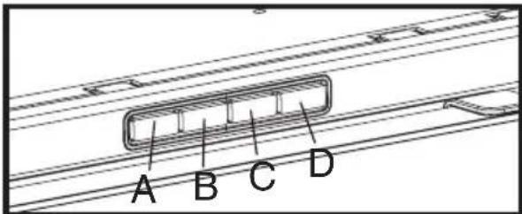
A. on/off light switch
B. on/off aspiration switch and minimum power selection
B+C. medium power selection aspiration switch
B+D. maximum power selection aspiration switch
Operation – All cooker hood versions
The cooker hood may be supplied with an automatic switching on/off device.
Closing the drawer the cooker hood switches off; opening the drawer the cooker hood switches on.
Use the high suction speed in cases of concentrated kitchen vapours. It is recommended that the cooker hood suction is switched on for 5 minutes prior to cooking and to leave in operation during cooking and for another 15 minutes approximately after terminating cooking.
12 INSTRUCTION ON MOUNTING AND USEGB
Cleaning
The cooker hood should be cleaned regularly internally and externally.
For cleaning use a cloth moistened with denatured alcohol or neutral liquid detergents. Avoid abrasive detergents.
Warning:
Failure to carry out the basic standards of the cleaning of the cooker hood and replacement of the filters may cause fire risks.
Therefore we recommend oserving these instructions.
Maintenance
Prior to any maintenance operation ensure that the cooker hood is disconnected from the power supply.
Grease filter
This must be cleaned once a month (and, in the case of the model with electronic control panel, each time that the letter F alternated to the selected speed appears on the display – see previous page) using non aggressive detergents either by hand or in the dish-washer, which must be set to a low temperature and a short cycle.
When washed in a dish-washer, the grease filter may discolour slightly, but this does not affect its filtering capacity. To remove the grease filter, pull the spring release handle (f) - (Fig. 2).
Only for model with electronic control panel:
After washing the anti-grease filter, depress knob B (see preceding page) for about 3 seconds. The letter F will disappear from the display.
Charcoal filter (filter version only)
It absorbs unpleasant odours caused by cooking.
The carbon filter should be replaced every six months (and in cases of the model with the electronic control panel, each time that the letter C appears on the display alternated to the selected speed – see previous page).
- Slide out the vapour collector.
- Remove the grease filter.
-
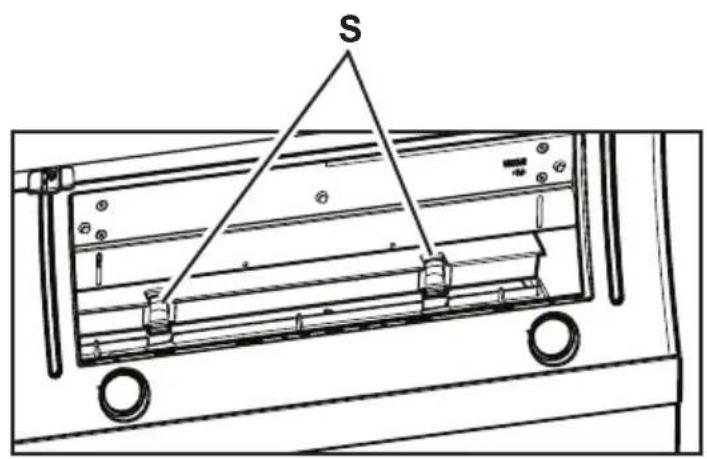
If the carbon filter is already mounted and requires replacement, depress the unblocking key (S - Fig. 10) and remove the filter downward.
-
Remount the grease filter.
If the carbon filter is not mounted:
-
Slide out the vapour collector.
-
Remove the grease filter.
-
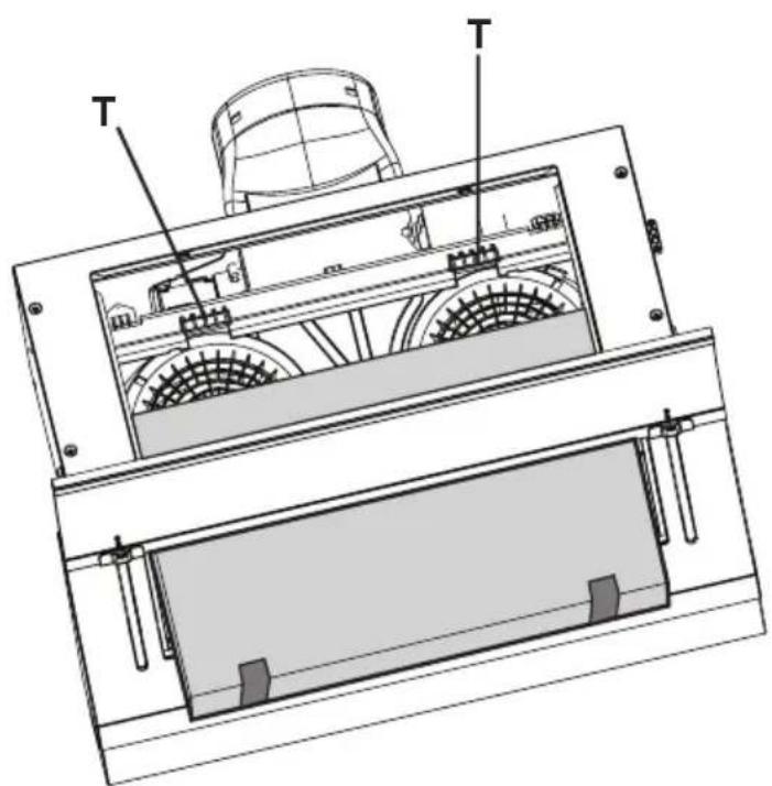
Insert the carbon filter in the upper hooks T and fix it using the lower hooks S (Fig. 10).
-
Remount the grease filter.
Only for model with electronic control panel:
After replacing the charcoal filter, depress knob B (see preceding page) for about 3 seconds.
The letter C will disappear from the display.
Replacing lamps - Fig. 4
Access the light compartment – according to the model in your possession, proceed as follows:
Warning!
Prior to touching the light bulbs ensure they are cooled down.
Model with halogen light bulbs.
Use a small screwdriver to act as a lever on the border of the light bulb housing in order to remove the light bulb. Replace the light bulb with a new PHILIPS STANDARD LINE code 425409 12V 20W 30° ∅35 12V GU4.
Carry out the replacement and the mounting of the new light bulb following the procedure in reverse.
Model with incandescent light bulbs:
Remove the vapour screen.
Remove the grease filter, it will then be possible to access the bulb housing area.
Unscrew the damaged light bulb and replace it with a new 40W max (E14 - B35) light bulb.
Model with PL light bulb.
Remove the vapour screen.
Remove the grease filter, it will then be possible to access the bulb housing area.
Extract the damaged light bulb and replace it with a new 9W-G23 (Cooker hood with two light bulbs) or 11W-G23 (Cooker hood with one light bulb).
If the lights do not work, make sure that the lamps are fitted properly into their housings before you call for technical assistance.
Caution
This appliance is designed to be operated by adults. Children should not be allowed to tamper with the controls or play with the appliance.
Do not use the cooker hood where the grill is not correctly fixed! The suctioned air must not be conveyed in the same channel used for fumes discharged by appliances powered by other than electricity. The environment must always be adequately aerated when the cooker hood and other appliances powered by other than electricity are used at the same time. Flambé cooking with a cooker hood is prohibited. The use of a free flame is damaging to the filters and may cause fire accidents, therefore free flame cooking must be avoided. Frying of foods must be kept under close control in order to avoid overheated oil catching fire. Carry out fumes discharging in accordance with the regulations in force by local laws for safety and technical restrictions.
- Description of the hood - Fig. 1
- Installation - Fig. 5-6
- GB INSTRUCTION ON MOUNTING AND USE11
- Electrical connection
- Operation – Model with electronic controls
- Warning!
- Operation – Model with button panel
- Operation – All cooker hood versions
- INSTRUCTION ON MOUNTING AND USEGB
- Cleaning
- Warning:
- Maintenance
- Grease filter
- Charcoal filter (filter version only)
- Only for model with electronic control panel:
- Replacing lamps - Fig. 4
- Model with halogen light bulbs.
- Model with incandescent light bulbs:
- Model with PL light bulb.
- Caution
Brand : SMEG
Model : KSET650X
Category : Basket