
DDX8046BT - GPS Navigation System KENWOOD - Free user manual and instructions
Find the device manual for free DDX8046BT KENWOOD in PDF.

| Product Type | GPS navigation system with DVD/CD/AM/FM receiver |
| Brand | Kenwood |
| Model | DDX8046BT |
| Dimensions (W x H x D) | 178 x 100 x 160 mm (standard DIN size) |
| Power Supply | 12 V DC, negative ground |
| Power Consumption | 15 A (protection fuse) |
| Main Functions | GPS navigation, DVD/CD player, AM/FM tuner, Bluetooth hands-free, USB/iPod connectivity, touch screen, rear view camera input, steering wheel control compatible |
| Connections | USB, iPod (via KCA-iP301V), AV inputs, preamp outputs front/rear/subwoofer/center, rear view camera input, GPS antenna, Bluetooth antenna |
| Bluetooth | Hands-free and audio streaming |
| Display | Color touch screen, adjustable backlight |
| Maximum Mounting Angle | 30° |
| Maintenance and Cleaning | Clean with a soft, dry cloth. Do not use solvents or abrasive products. |
| Safety | Professional installation recommended. Disconnect battery before installation. Use only the provided screws. Do not block the cooling fan. |
| Spare Parts and Repairability | Replacement fuse: 15A. Mounting screws provided. Optional adapters available (steering wheel remote, TMC tuner, etc.). |
| General Information | Manual available for free download in PDF format. Technical support via Kenwood website. |
Frequently Asked Questions - DDX8046BT KENWOOD
User questions about DDX8046BT KENWOOD
0 question about this device. Answer the ones you know or ask your own.
Ask a new question about this device
Download the instructions for your GPS Navigation System in PDF format for free! Find your manual DDX8046BT - KENWOOD and take your electronic device back in hand. On this page are published all the documents necessary for the use of your device. DDX8046BT by KENWOOD.
USER MANUAL DDX8046BT KENWOOD
natural_image
Line drawing of a twisted rope or cable with no text or symbols

natural_image
Illustration of a bundle of celery with a label (②) and a scale marker (1), no text or symbols present.
natural_image
Isometric view of a rectangular frame with mounting holes, labeled with number 10 and dimension line (no text or symbols on the frame itself)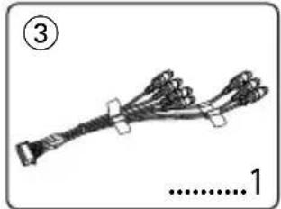
natural_image
Illustration of a cable or connector with multiple wires and connectors, labeled with numbers 3 and 1 (no text or symbols on the diagram itself)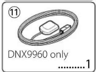
natural_image
Illustration of a bundle of bundled wires or wires with no visible text or symbols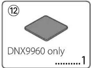
natural_image
Line drawing of a mechanical tool with a handle and base, labeled with number 5 and '2' (no text or symbols on the tool itself)
natural_image
Illustration of a knitted cable with a loop and connector (no text or symbols)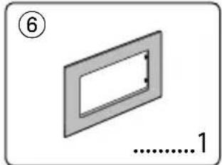
natural_image
Simple 3D diagram of a rectangular frame with a small internal slot, labeled with number 6 and dimension '1' (no text or symbols beyond labels)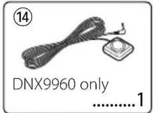

natural_image
Simple line drawing of two rectangular strips on a flat surface, labeled with number 7 and '1' (no text or symbols within the diagram itself)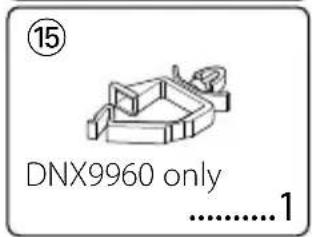

natural_image
Simple line drawing of a screw with no text or symbolsInstallation Procedure
- To prevent a short circuit, remove the key from the ignition and disconnect the ⊖ battery.
- Make the proper input and output wire connections for each unit.
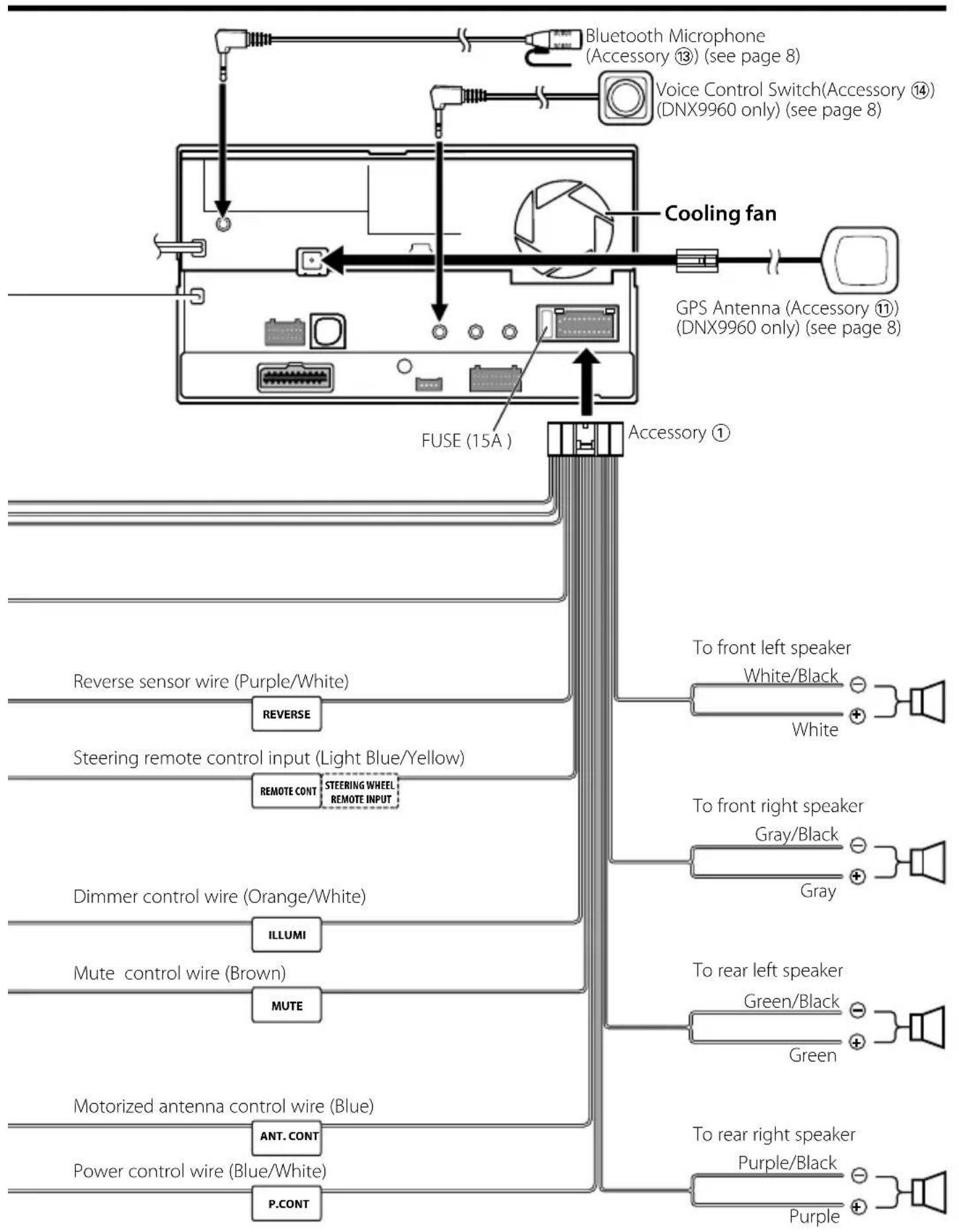
- Connect the speaker wires of the wiring harness.
- Connect the wiring harness wires in the following order: ground, battery, ignition.
- Connect the wiring harness connector to the unit.
- Install the unit in your car.
- Reconnect the ⊖ battery.
- Press the reset button.
- Perform the Initial Setup. (Refer to the Instruction Manual.)
▲WARNING
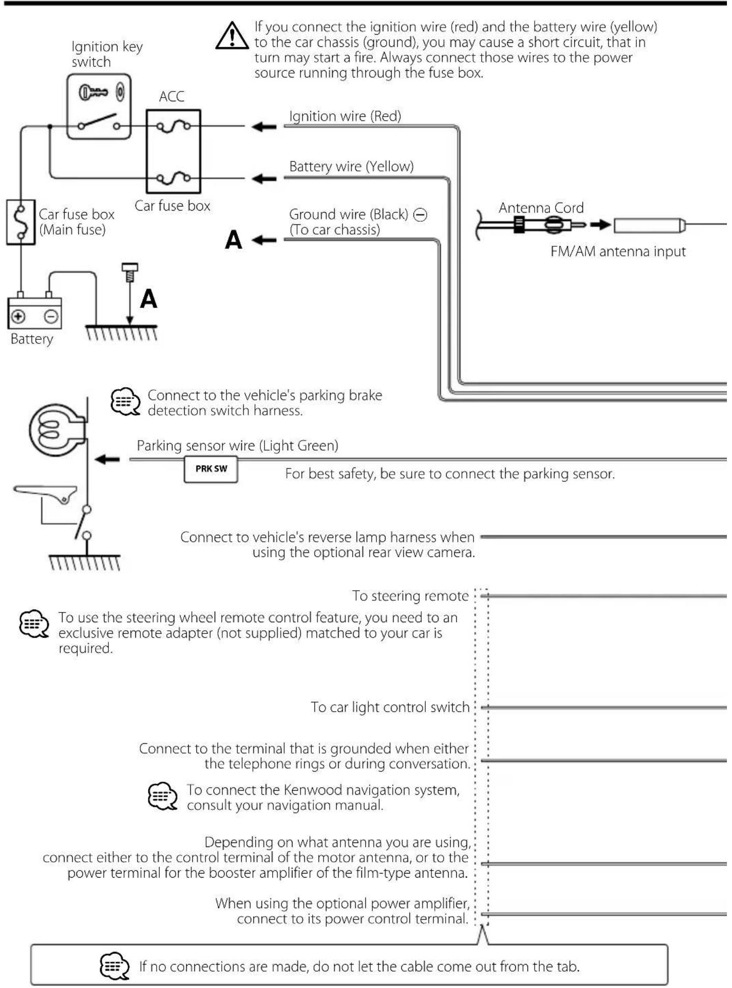
- If you connect the ignition wire (red) and the battery wire (yellow) to the car chassis (ground), you may cause a short circuit, that in turn may start a fire. Always connect those wires to the power source running through the fuse box.
- Do not cut out the fuse from the ignition wire (red) and the battery wire (yellow). The power supply must be connected to the wires via the fuse.
Acquiring GPS Signals
The first time you turn on DNX9960, you must wait while the system acquires satellite signals for the first time. This process could take up to several minutes. Make sure your vehicle is outdoors in an open area away from tall buildings and trees for fastest acquisition. After the system acquires satellites for the first time, it will acquire satellites quickly each time thereafter.
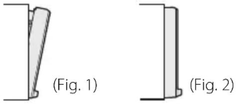
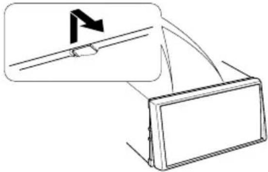
About the Front Panel
When removing the product from the box or installing it, the front panel may be positioned at the angle shown in (Fig. 1). This is due to the characteristics of mechanism the product is equipped with.
When the product is first powered on works
properly, the front panel will automatically move into the position (initial setting angle) shown in (Fig. 2).
After the Installation
After the installation, perform the Initial Setup by referring to the instruction manual.

- Mounting and wiring this product requires skills and experience. For best safety, leave the mounting and wiring work to professionals.
- Make sure to ground the unit to a negative 12V DC power supply.
- Do not install the unit in a spot exposed to direct sunlight or excessive heat or humidity. Also avoid places with too much dust or the possibility of water splashing.
- Do not use your own screws. Use only the screws provided. If you use the wrong screws, you could damage the unit.
- If the power is not turned ON ("PROTECT" is displayed), the speaker wire may have a short-circuit or touched the chassis of the vehicle and the protection function may have been activated. Therefore, the speaker wire should be checked.
- If your car's ignition does not have an ACC position, connect the ignition wires to a power source that can be turned on and off with the ignition key. If you connect the ignition wire to a power source with a constant voltage supply, such as with battery wires, the battery may be drained.
- If the console has a lid, make sure to install the unit so that the faceplate will not hit the lid when closing and opening.
- If the fuse blows, first make sure the wires aren't touching to cause a short circuit, then replace the old fuse with one with the same rating.
- Insulate unconnected wires with vinyl tape or other similar material. To prevent a short circuit, do not remove the caps on the ends of the
unconnected wires or the terminals.
- Connect the speaker wires correctly to the terminals to which they correspond. The unit may be damaged or fail to work if you share the ⏻ wires or ground them to any metal part in the car.
- When only two speakers are being connected to the system, connect the connectors either to both the front output terminals or to both the rear output terminals (do not mix front and rear). For example, if you connect the ⊕ connector of the left speaker to a front output terminal, do not connect the ⊖ connector to a rear output terminal.
- After the unit is installed, check whether the brake lamps, blinkers, wipers, etc. on the car are working properly.
- Mount the unit so that the mounting angle is 30irc or less.
- This unit has the cooling fan (page 5) to decrease the internal temperature. Do not mount the unit in a place where the cooling fan of the unit are blocked. Blocking these openings will inhibit the cooling of the internal temperature and result in malfunction.
- Do not press hard on the panel surface when installing the unit to the vehicle. Otherwise scars, damage, or failure may result.
- Reception may drop if there are metal objects near the Bluetooth antenna.
Bluetooth antenna unit
natural_image
Simple line drawing of a rectangular frame with a circular top and bottom edge, no text or symbols present.
CAUTION
Install this unit in the console of your vehicle.
Do not touch the metal part of this unit during and shortly after the use of the unit. Metal part such as the heat sink and enclosure become hot.
flowchart
graph TD
    A["Ignition key switch"] --> B["ACC"]
    B --> C["Car fuse box (Main fuse)"]
    C --> D["Battery"]
    D --> E["Connect to the vehicle's parking brake detection switch harness."]
    E --> F["Parking sensor wire (Light Green)"]
    F --> G["PRK SW"]
    G --> H["For best safety, be sure to connect the parking sensor."]
    H --> I["FM/AM antenna input"]
    J["Antenna Cord"] --> K["FM/AM antenna input"]
    L["To car light control switch"] --> M["To steering remote"]
    N["To car chassis"] --> O["To car chassis"]
    P["To car chassis"] --> Q["To car chassis"]
    R["To car chassis"] --> S["To car chassis"]
    T["To car chassis"] --> U["To car chassis"]
    V["To car chassis"] --> W["To car chassis"]
    X["To car chassis"] --> Y["To car chassis"]
    Z["To car chassis"] --> AA["To car chassis"]
    AB["To car chassis"] --> AC["To car chassis"]
    AD["To car chassis"] --> AE["To car chassis"]
    AF["To car chassis"] --> AG["To car chassis"]
    AH["To car chassis"] --> AI["To car chassis"]
    AJ["To car chassis"] --> AK["To car chassis"]
    AL["To car chassis"] --> AM["To car chassis"]
    AN["To car chassis"] --> AO["To car chassis"]
    AP["If no connections are made, do not let the cable come out from the tab."]
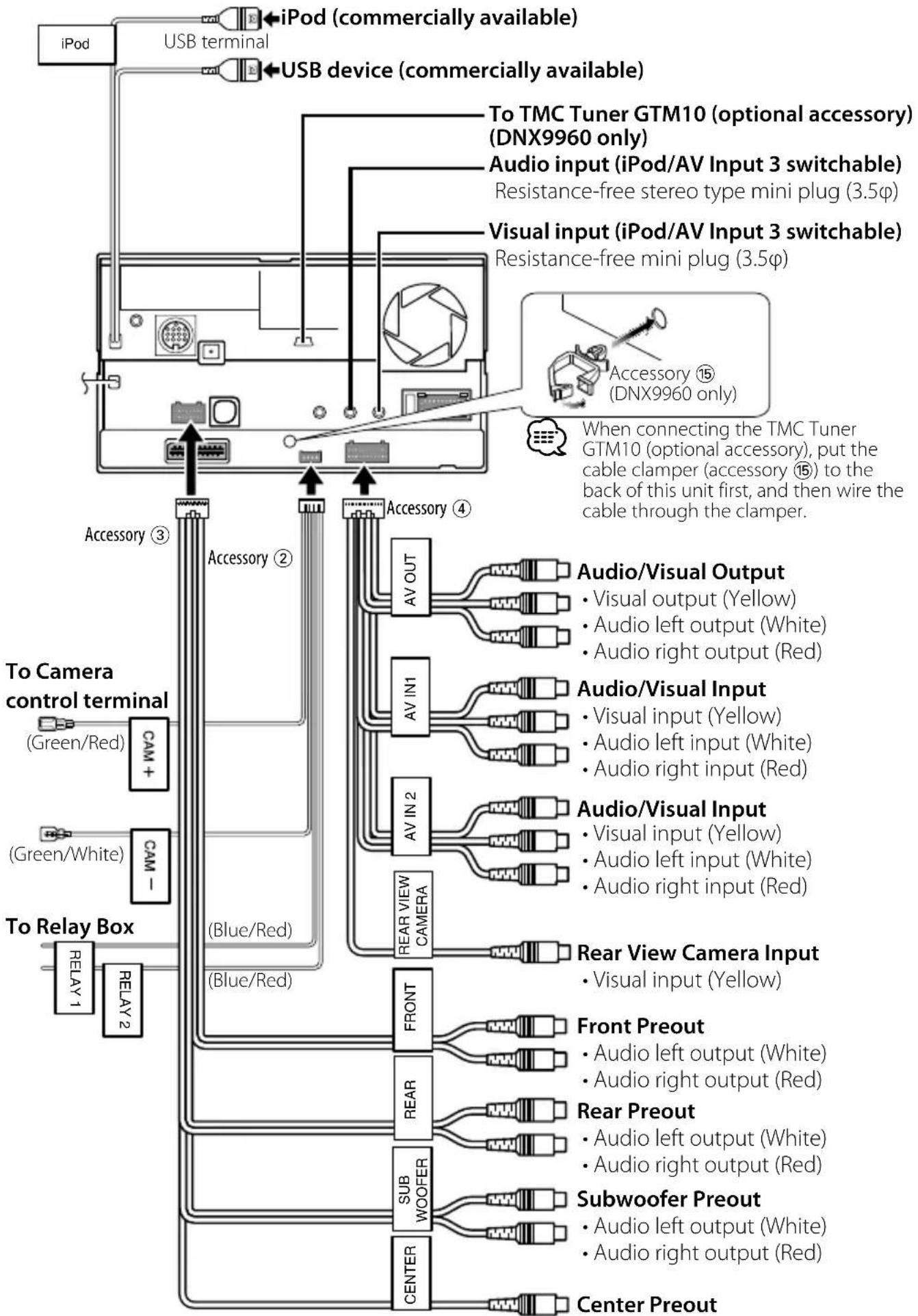
flowchart
graph TD
A["iPod"] --> B["USB terminal"]
B --> C["USB device (commercially available)"]
C --> D["To TMC Tuner GTM10 (optional accessory) (DNX9960 only)"]
C --> E["Audio input (iPod/AV Input 3 switchable)"]
C --> F["Resistance-free stereo type mini plug (3.5φ)"]
C --> G["Visual input (iPod/AV Input 3 switchable)"]
C --> H["Resistance-free mini plug (3.5φ)"]
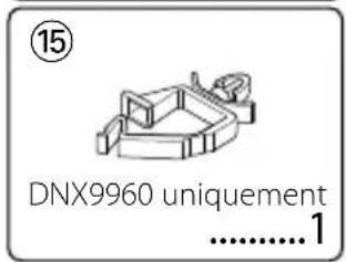
I["Accessory ⑮ (DNX9960 only)"] --> J["When connecting the TMC Tuner GTM10 (optional accessory), put the cable clamper (accessory ⑮) to the back of this unit first, and then wire the cable through the clamper."]
K["To Camera control terminal (Green/Red)"] --> L["CAM +"]
M["(Green/White)"] --> N["CAM -"]
O["To Relay Box"] --> P["RELAY 1"]
O --> Q["RELAY 2"]
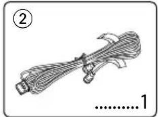
R["Accessory ③"] --> S["Accessory ②"]
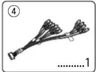
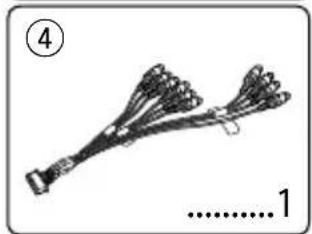
T["Accessory ④"] --> U["AV OUT"]
V["AV IN1"] --> W["Audio/Visual Output"]
V --> X["Audio/Visual Input"]
V --> Y["Audio/Visual Input"]
V --> Z["Audio/Visual Input"]
V --> AA["Audio/Visual Input"]
AB["REAR VIEW CAMERA"] --> AC["Visual input (Yellow)"]
AB --> AD["Audio left input (White)"]
AB --> AE["Audio right input (Red)"]
AF["Rear View Camera Input"] --> AG["Visual input (Yellow)"]
AH["FRONT"] --> AI["Audio left output (White)"]
AH --> AJ["Audio right output (Red)"]
AK["REAR"] --> AL["Audio left output (White)"]
AK --> AM["Audio right output (Red)"]
AN["SUB WOOFER"] --> AO["Audio left output (White)"]
AN --> AP["Audio right output (Red)"]
AQ["CENTER"] --> AR["Audio left output (White)"]
AQ --> AS["Audio right output (Red)"]
AT["Center Preout"] --> AU["Subwoofer Preout"]
AT --> AV["Front Preout"]
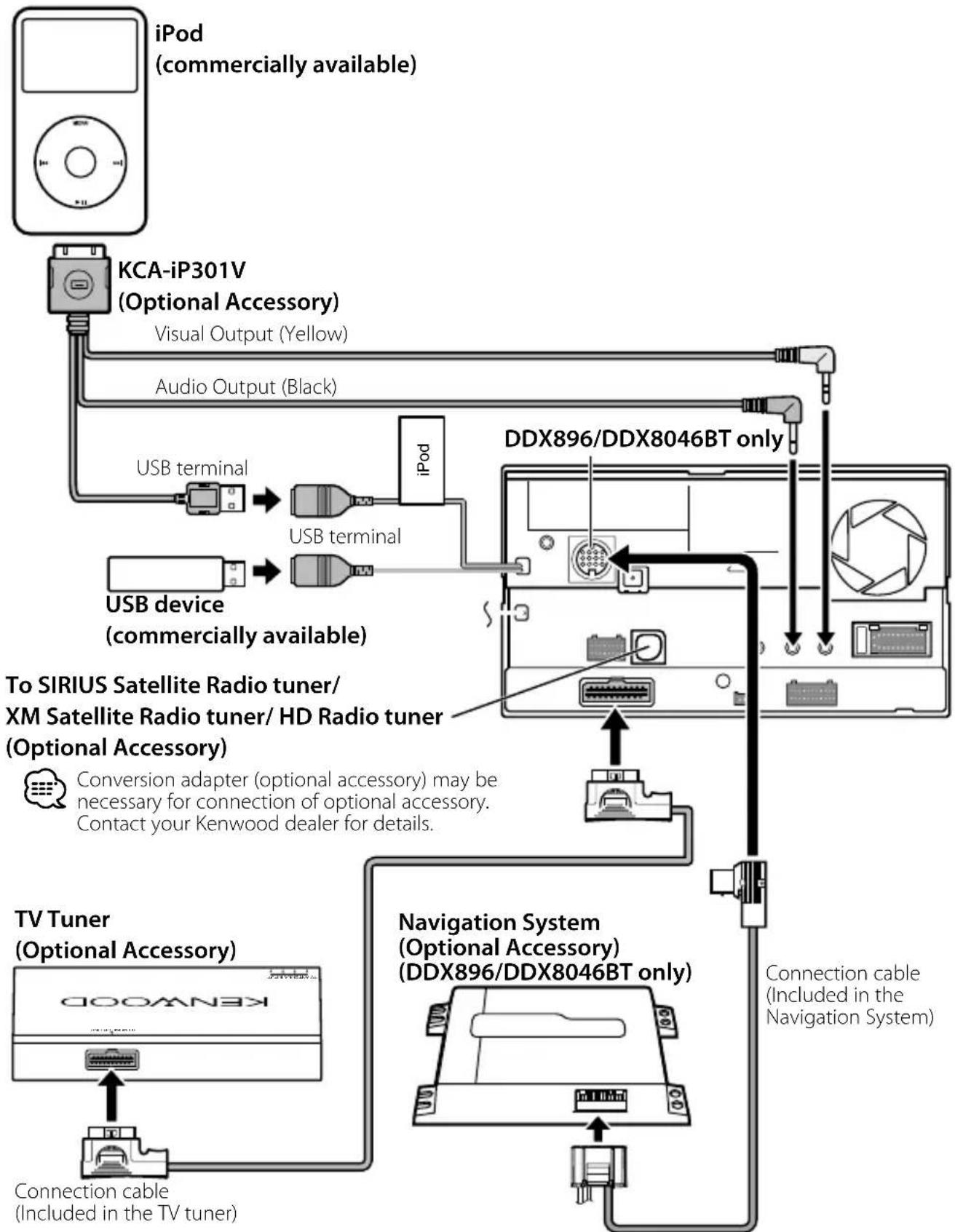
flowchart
graph TD
    A["iPod (commercially available)"] --> B["KCA-iP301V (Optional Accessory)"]
    B --> C["Visual Output (Yellow)"]
    B --> D["Audio Output (Black)"]
    B --> E["USB terminal"]
    E --> F["USB terminal"]
    F --> G["iPod"]
    G --> H["DDX896/DDX8046BT only"]
    H --> I["To SIRIUS Satellite Radio tuner/ XM Satellite Radio tuner/ HD Radio tuner (Optional Accessory)"]
    I --> J["Conversion adapter (optional accessory) may be necessary for connection of optional accessory. Contact your Kenwood dealer for details."]
    J --> K["TV Tuner (Optional Accessory)"]
    K --> L["Connection cable (Included in the TV tuner)"]
    L --> M["Navigation System (Optional Accessory) (DDX896/DDX8046BT only)"]
    M --> N["Connection cable (Included in the Navigation System)"]

Navigation units that can be connected to this unit. (As of December, 2009):
- KNA-G610
• KNA-G630
For latest information, access the www.kenwood.com/cs/ce/.
Installing the GPS Antenna (DNX9960 only)
GPS antenna is installed inside of the car. It should be installed as horizontally as possible to allow easy reception of the GPS satellite signals.
To mount the GPS antenna inside your vehicle:
- Clean your dashboard or other surface.
- Peel the backing off of the adhesive on the bottom of the metal plate (accessory ⑫).
- Press the metal plate (accessory ⑫) down firmly on your dashboard or other mounting surface. You can bend the metal plate (accessory ⑫) to conform to a curved surface, if necessary.
- Place the GPS antenna (accessory ⑪) on top of the metal plate (accessory ⑫).
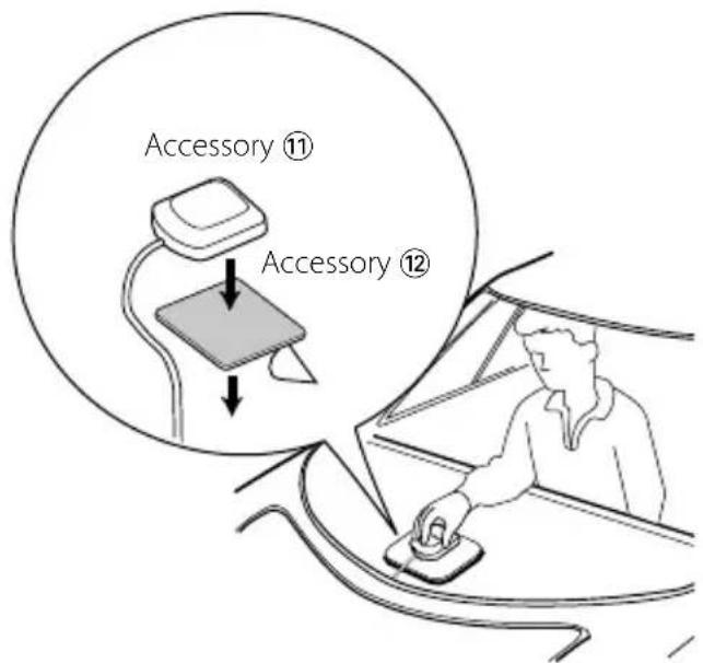

- Depending on the type of car, reception of the GPS satellite signals might not be possible with an inside installation.
- The GPS antenna should be installed at a position that is spaced at least 12 inch (30 cm) from cellular phone or other transmitting antennas. Signals from the GPS satellite may be interfered with by these types of communication.
- Painting the GPS antenna with (metallic) paint may cause a drop in performance.
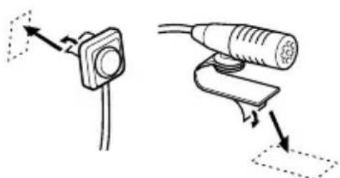
Installing the Talk Switch (DNX9960 only) and the Microphone Unit
- Check the installation position of the microphone (accessory ⑬) and the Talk switch (accessory ⑭).
- Remove oil and other dirt from the installation surface.
- Install the microphone.
- Wire the microphone cable up to the unit with it secured at several positions using tape or the like.
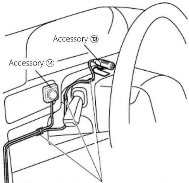
Fix a cable with a commercial item of tape.
natural_image
Diagram showing two mechanical or electrical components with directional arrows, no text or symbols present.Peel the release coated paper of double-face adhesive tape to fix on the place shown above.
natural_image
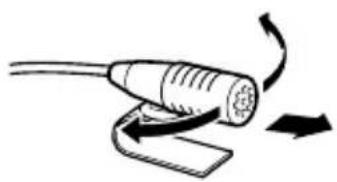
Illustration of a cable being inserted into a microphone with a slide nearby (no text or symbols)Adjust the direction of the microphone to the driver.

Install the microphone as far as possible from the cell-phone.
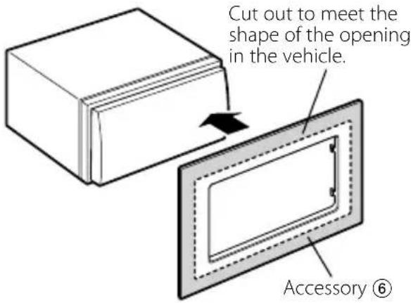
For General Motors
- Cut out accessory ⑥ to meet the shape of the opening of the center console.
- Attach accessory ⑥ to the unit.
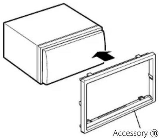
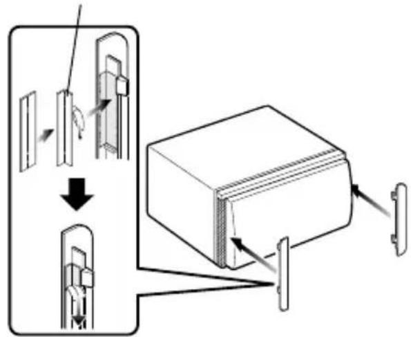
For Volkswagen
- Attach accessory ⑩ to the unit.
For Toyota/Scion
- Cut out accessory ⑥ as illustrated.
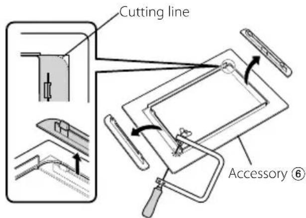
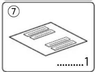
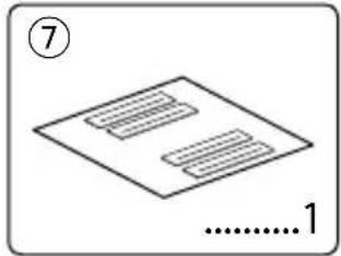
- Fold double-sided adhesive (accessory ⑦) along the slit and attach it to accessory ⑥ cut-out against the center rib as illustrated. Use 2 pieces of accessory ⑦ for 1 accessory ⑥ cut-out.
- Attach accessory ⑥ cut-out to the unit.
Accessory ⑦
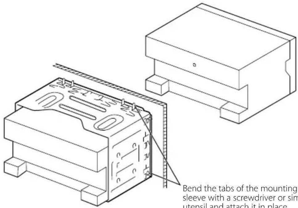
Bend the tabs of the mounting sleeve with a screwdriver or similar utensil and attach it in place.

Make sure that the unit is installed securely in place. If the unit is unstable, it may malfunction (eg, the sound may skip).
Installation on Toyota, Nissan or Mitsubishi Car using Brackets
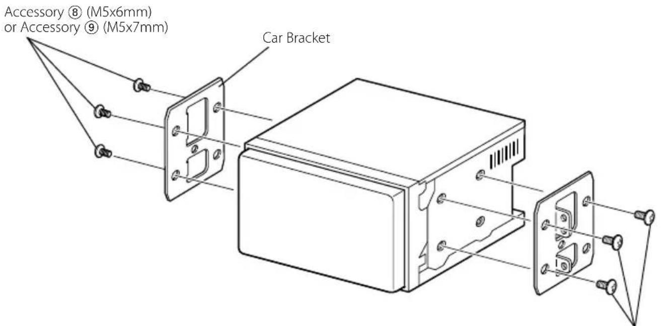
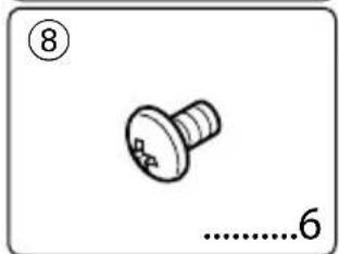
Accessory ⑧ (M5x6mm) or Accessory ⑨ (M5x7mm)
Removing the Hard Rubber Frame (escutcheon)
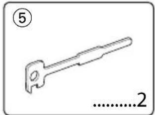
- Engage the catch pins on the removal tool ⑤ and remove the two locks on the lower level.
Lower the frame and pull it forward as shown in the figure.
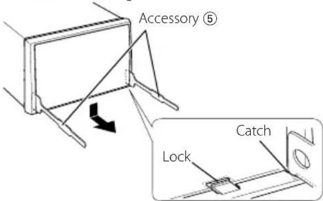

- The frame can be removed from the top side in the same manner.
- When the lower level is removed, remove the upper two locations.
natural_image
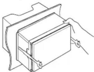
Diagram showing a mechanical component with an arrow indicating direction, no text or symbols presentRemoving the Unit
-
Remove the hard rubber frame by referring to the removal procedure in the section
. -
Insert the two removal tools ⑤ deeply into the slots on each side, as shown.
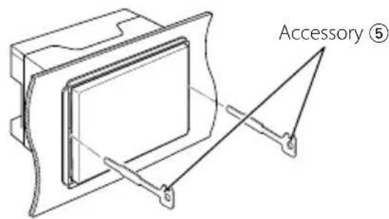
- Lower the removal tool toward the bottom, and pull out the unit halfway while pressing towards the inside.
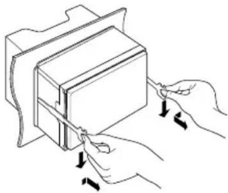
natural_image
Illustration of hands using a tool to adjust or install a rectangular object, with arrows indicating motion (no text or symbols)
- Be careful to avoid injury from the catch pins on the removal tool.
- Pull the unit all the way out with your hands, being careful not to drop it.
natural_image
Line drawing of a hand inserting a rectangular component into a housing (no text or symbols)Accessoires

natural_image
Line drawing of a twisted rope or cable with no text or symbols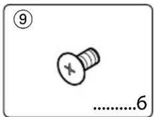
natural_image
Illustration of a bundle of celery with a label (②) and a scale marker (1), no text or symbols present.
natural_image
Isometric view of a rectangular frame with mounting holes, labeled with number 10 and dimension line (no text or symbols on the frame itself)
natural_image
Illustration of a cable or connector with multiple wires and connectors, labeled with numbers 3 and 1 (no text or symbols on the diagram itself)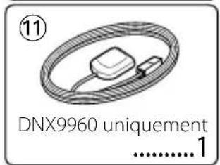
natural_image
Illustration of a bundle of wires or wires with no visible text or symbols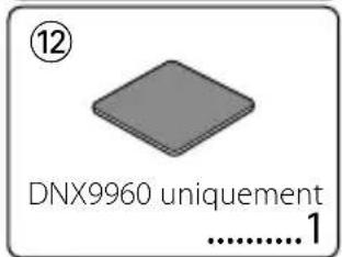

natural_image
Line drawing of a mechanical tool with a handle and base, labeled with number 5 and '2' (no text or symbols on the tool itself)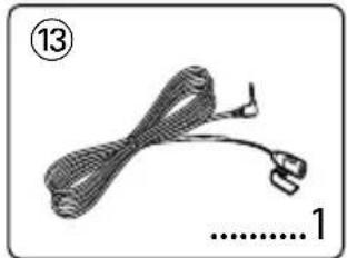
natural_image
Illustration of a knitted cable with a loop and connector, labeled with number 13 (no text or symbols on the cable itself)
natural_image
Simple 3D diagram of a rectangular frame with a small internal slot, labeled with number 6 and dimension '1' (no text or symbols beyond labels)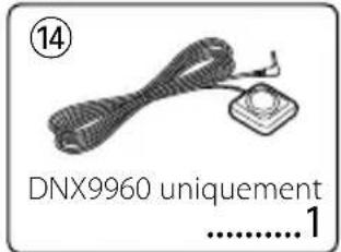
natural_image
Simple line drawing of a screw with no text or symbolsnatural_image
Diagram showing two mechanical components with no text or symbols, labeled (Fig. 1) and (Fig. 2), without any readable content.natural_image
Front view of a blank rectangular frame with no text or symbols on the frame itself
ATTENTION
www.kenwood.com/cs/ce/.
natural_image
Diagram showing two mechanical or electrical components with directional arrows, no text or symbols present.natural_image
Diagram of a cable being inserted into a device with directional arrows indicating motion (no text or symbols)
natural_image
Diagram showing a mechanical component with an arrow indicating direction, no text or symbols presentnatural_image
Illustration of hands using a tool to adjust or install a rectangular object, with arrows indicating movement (no text or symbols present)
natural_image
Line drawing of a hand inserting a component into a housing (no text or symbols)Accesorios
natural_image
Line drawing of a twisted rope or cable with no text or symbols

natural_image
Illustration of a bundle of celery with a label (②) and a scale marker (1), no text or symbols present.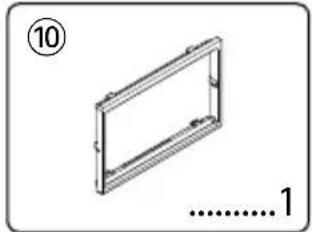
natural_image
Isometric view of a rectangular frame with mounting holes, labeled with number 10 and dimension line (no text or symbols on the frame itself)
natural_image
Illustration of a cable or connector with multiple wires and connectors, labeled with numbers 3 and 1 (no text or symbols on the diagram itself)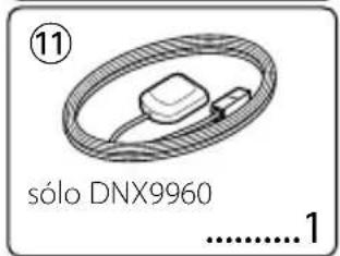

natural_image
Illustration of a bundle of bundled wires or wires with no visible text or symbols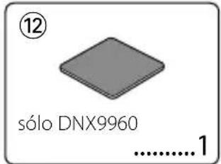

natural_image
Line drawing of a mechanical tool with a handle and base, labeled with number 5 and '2' (no text or symbols on the tool itself)
natural_image
Illustration of a knitted cable with a loop and connector, labeled with number 13 (no text or symbols on the cable itself)
natural_image
Simple 3D diagram of a rectangular frame with a small internal slot, labeled with number 6 and dimension '1' (no text or symbols beyond labels)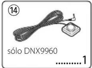
natural_image
Simple line drawing of two parallel rectangular strips on a flat surface, labeled with number 7 and '1' (no text or symbols within the diagram itself)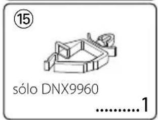

natural_image
Simple line drawing of a screw with no text or symbolsnatural_image
Diagram showing two mechanical components with no text or symbols, labeled (Fig. 1) and (Fig. 2), without any readable content.natural_image
Front view of a blank rectangular frame with control buttons at the bottom (no text or symbols on the frame itself)
PRECAUCIÓN
natural_image
Diagram showing a device with a sensor and a handheld device connected to a connector (no text or symbols present)natural_image
Illustration of a cable being inserted into a connector with an arrow indicating rotation (no text or symbols)natural_image
Diagram showing a mechanical component with an arrow indicating direction, no text or symbols presentnatural_image
Illustration of hands using a tool to adjust or install a rectangular object, with arrows indicating motion (no text or symbols)
natural_image
Line drawing of a hand inserting a component into a housing (no text or symbols)KENWOOD

- Installation Procedure
- ▲WARNING
- Acquiring GPS Signals
- About the Front Panel
- After the Installation
- CAUTION
- Installing the GPS Antenna (DNX9960 only)
- To mount the GPS antenna inside your vehicle:
- Installing the Talk Switch (DNX9960 only) and the Microphone Unit
- For General Motors
- For Volkswagen
- For Toyota/Scion
- Installation on Toyota, Nissan or Mitsubishi Car using Brackets
- Removing the Hard Rubber Frame (escutcheon)
- Removing the Unit
- Accessoires
- ATTENTION
- Accesorios
- PRECAUCIÓN
- KENWOOD
Brand : KENWOOD
Model : DDX8046BT
Category : GPS Navigation System