
P 20SA2 - Plane HiKOKI - Free user manual and instructions
Find the device manual for free P 20SA2 HiKOKI in PDF.
| Product type | Electric planer |
| Brand | HiKOKI |
| Model | P 20SA2 |
| Supply voltage | 110-240 V depending on region |
| Rated power | 720 W |
| Cutting width | 82 mm |
| Maximum cutting depth | 3 mm |
| Weight (according to EPTA) | 3.4 kg |
| No-load speed | 14 000 rpm |
| Applications | Planing of timber and wood panels |
| Sound pressure level | 85 dB(A) |
| Sound power level | 96 dB(A) |
| Vibrations (planing softwood) | 2.5 m/s² |
| Blade type | Carbide double-edged blades or re-sharpenable blades |
| Dust extraction system | Dust adapter included |
| Routine maintenance | Cleaning of ventilation openings, checking brushes and blades |
| Replaceable wear parts | Carbon brushes, belt, blades |
| Safety | Automatic stop in case of jamming, double insulation, safety switch |
| Warranty | Compliant with national regulations, covers manufacturing defects |
Frequently Asked Questions - P 20SA2 HiKOKI
User questions about P 20SA2 HiKOKI
0 question about this device. Answer the ones you know or ask your own.
Ask a new question about this device
Download the instructions for your Plane in PDF format for free! Find your manual P 20SA2 - HiKOKI and take your electronic device back in hand. On this page are published all the documents necessary for the use of your device. P 20SA2 by HiKOKI.
USER MANUAL P 20SA2 HiKOKI
Read through carefully and understand these instructions before use.
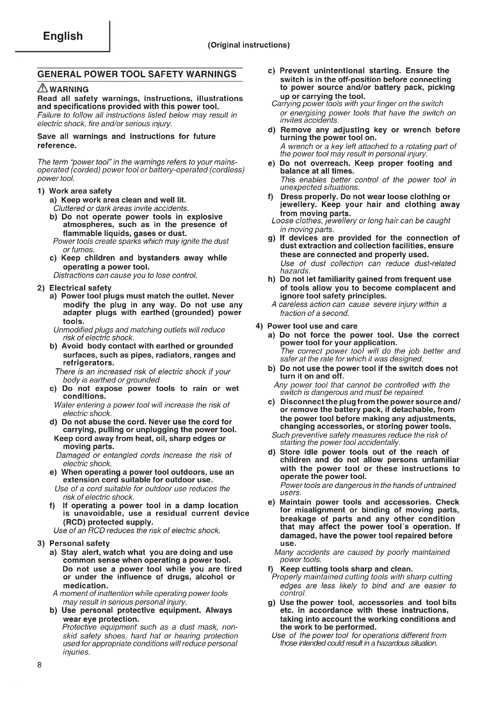
Read all safety warnings, instructions, illustrations and specifications provided with this power tool.
Failure to follow all instructions listed below may result in electric shock, fire and/or serious injury.
Save all warnings and instructions for future reference.
The term "power tool" in the warnings refers to your mains-operated (corded) power tool or battery-operated (cordless) power tool.
1) Work area safety
a) Keep work area clean and well lit.
Cluttered or dark areas invite accidents.
b) Do not operate power tools in explosive atmospheres, such as in the presence of flammable liquids, gases or dust.
Power tools create sparks which may ignite the dust or fumes.
c) Keep children and bystanders away while operating a power tool.
Distractions can cause you to lose control.
2) Electrical safety
a) Power tool plugs must match the outlet. Never modify the plug in any way. Do not use any adapter plugs with earthed (grounded) power tools.
Unmodified plugs and matching outlets will reduce risk of electric shock.
b) Avoid body contact with earthed or grounded surfaces, such as pipes, radiators, ranges and refrigerators.
There is an increased risk of electric shock if your body is earthed or grounded.
c) Do not expose power tools to rain or wet conditions.
Water entering a power tool will increase the risk of electric shock.
d) Do not abuse the cord. Never use the cord for carrying, pulling or unplugging the power tool.
Keep cord away from heat, oil, sharp edges or moving parts.
Damaged or entangled cords increase the risk of electric shock.
e) When operating a power tool outdoors, use an extension cord suitable for outdoor use.
Use of a cord suitable for outdoor use reduces the risk of electric shock.
f) If operating a power tool in a damp location is unavoidable, use a residual current device (RCD) protected supply.
Use of an RCD reduces the risk of electric shock.
3) Personal safety
a) Stay alert, watch what you are doing and use common sense when operating a power tool. Do not use a power tool while you are tired or under the influence of drugs, alcohol or medication.
A moment of inattention while operating power tools may result in serious personal injury.
b) Use personal protective equipment. Always wear eye protection.
Protective equipment such as a dust mask, nonskid safety shoes, hard hat or hearing protection used for appropriate conditions will reduce personal injuries.
c) Prevent unintentional starting. Ensure the switch is in the off-position before connecting to power source and/or battery pack, picking up or carrying the tool.
Carrying power tools with your finger on the switch or energising power tools that have the switch on invites accidents.
d) Remove any adjusting key or wrench before turning the power tool on.
A wrench or a key left attached to a rotating part of the power tool may result in personal injury.
e) Do not overreach. Keep proper footing and balance at all times.
This enables better control of the power tool in unexpected situations.
f) Dress properly. Do not wear loose clothing or jewellery. Keep your hair and clothing away from moving parts.
Loose clothes, jewellery or long hair can be caught in moving parts.
g) If devices are provided for the connection of dust extraction and collection facilities, ensure these are connected and properly used.
Use of dust collection can reduce dust-related hazards.
h) Do not let familiarity gained from frequent use of tools allow you to become complacent and ignore tool safety principles.
A careless action can cause severe injury within a fraction of a second.
4) Power tool use and care
a) Do not force the power tool. Use the correct power tool for your application.
The correct power tool will do the job better and safer at the rate for which it was designed.
b) Do not use the power tool if the switch does not turn it on and off.
Any power tool that cannot be controlled with the switch is dangerous and must be repaired.
c) Disconnect the plug from the power source and/ or remove the battery pack, if detachable, from the power tool before making any adjustments, changing accessories, or storing power tools.
Such preventive safety measures reduce the risk of starting the power tool accidentally.
d) Store idle power tools out of the reach of children and do not allow persons unfamiliar with the power tool or these instructions to operate the power tool.
Power tools are dangerous in the hands of untrained users.
e) Maintain power tools and accessories. Check for misalignment or binding of moving parts, breakage of parts and any other condition that may affect the power tool's operation. If damaged, have the power tool repaired before use.
Many accidents are caused by poorly maintained power tools.
f) Keep cutting tools sharp and clean.
Properly maintained cutting tools with sharp cutting edges are less likely to bind and are easier to control.
g) Use the power tool, accessories and tool bits etc. in accordance with these instructions, taking into account the working conditions and the work to be performed.
Use of the power tool for operations different from those intended could result in a hazardous situation.
h) Keep handles and grasping surfaces dry, clean and free from oil and grease.
Slippery handles and grasping surfaces do not allow for safe handling and control of the tool in unexpected situations.
5) Service
a) Have your power tool serviced by a qualified repair person using only identical replacement parts.
This will ensure that the safety of the power tool is maintained.
PRECAUTION
Keep children and infirm persons away.
When not in use, tools should be stored out of reach of children and infirm persons.
PLANER SAFETY WARNINGS
- Wait for the cutter to stop before settling the tool down.
An exposed rotating cutter may engage the surface leading to possible loss of control and serious injury.
- Hold the power tool by insulated gripping surfaces, because the cutter may contact its own cord. Cutting a "live" wire may make exposed metal parts power tool "live" and could give the operator an electric shock.
- Use clamps or another practical way to secure and support the workpiece to a stable platform. Holding the workpiece by your hand or against the body leaves it unstable and may lead to loss of control.
- Do not use the Planer with the blades facing upward (as stationary type planer).
- Use dust collection adapter if need to reduce dust related hazards.
(1) Unscrew the Chip guide (Item no. 17 show in assembly drawing) on housing.
(2) Mount dust collection adapter on housing with screws instead of the Chip guide. Dust collection adapter (Code no. 317279)
(3) Connect the dust extraction and collection facilities with the tube of dust collection adapter firmly.
SPECIFICATIONS
| Voltage (by areas) * | (110V, 115V, 120V, 127V, 220V, 230V, 240V)~ |
| Power Input | 720 W* |
| Cutting Width | 82 mm |
| Max. Cutting Depth | 3 mm |
| Weight ** | 3.4 kg |
| No-Load Speed | 14000 / min |
- Be sure to check the nameplate on product as it is subject to change by areas.
** According to EPTA-Procedure 01/2014
STANDARD ACCESSORIES
In addition to the main unit (1 unit), the package contains the accessories listed on page 35.
Standard accessories are subject to change without notice.
APPLICATIONS
Planing various wooden planks and panels.
(See Fig. 1-4)
PRIOR TO OPERATION
- Power source
Ensure that the power source to be utilized conforms to the power requirements specified on the nameplate.
- Power switch
Ensure that the power switch is in the OFF position. If the plug is connected to a receptacle while the power switch is in the ON position, the power tool will start operating immediately, which could cause a serious accident.
- Extension cord
When the work area is removed from the power source, use an extension cord of sufficient thickness and rated capacity. The extension cord should be kept as short as practicable.
- Prepare a stable wooden workbench suitable for planing operation. As a poorly balanced workbench creates a hazard, ensure it is securely positioned on firm, level ground.
PLANING PROCEDURES
- Adjusting the cutter depth:
(1) Turn the knob in the direction indicated by the arrow in Fig. 5 (clockwise), until the triangular mark is aligned with the desired cutting depth on the scale. The scale unit is graduated in millimeters.
(2) The cutting depth can be adjusted within a 0-3 mm.
2. Surface cutting:
Rough cutting should be accomplished at large cutting depths and at a suitable speed so that shaw are smoothly ejected from the machine. To ens a smoothly finished surface, finish cutting should be accomplished at small cutting depths and at low feeding speed.
3. Beginning and ending the cutting operation:
As shown in Fig. 6, place the front base of the planer on the material and support the planer horizontally. Turn ON the power switch, and slowly operate the planer toward the leading edge of the material. Firmly depress the front half of the planer at the first stage of cutting, as shown in Fig. 7, depress the rear half of the planer at the end of the cutting operation. The planer must always be kept flat throughout the entire cutting operation.
- Precaution after finishing the planing operation: When the planer is suspended with one hand after finishing the planing operation, ensure that the cutting blades (base) of the planer do not contact or come too near your body. Failure to do so could result in serious injury.
CARBIDE BLADE ASSEMBLY AND DISASSEMBLY AND ADJUSTMENT OF CUTTER BLADE HEIGHT (FOR DOUBLE EDGED BLADE TYPE)
1. Carbide blade disassembly:
(1) As shown in Fig. 8, loosen the blade holder with the attached box wrench.
(2) As shown in Fig. 9, remove the carbide blade by sliding it with the attached box wrench.
CAUTION
Be careful not to injure your hands.
2. Carbide blade assembly:
CAUTION
Prior to assembly, thoroughly wipe off all accumulated on the carbide blade.
(1) As shown in Fig. 10, lift set plate (B) and insert the new carbide blade between cutter block and set plate (B).
(2) As shown in Fig. 11, mount the new carbide blade by sliding it on the set plate (B) so that the blade tip projects by 1mm from the end of the cutter block.
(3) As shown in Fig. 12, fix the bolts at the blade holder after blade replacement has been completed.
(4) Turn the cutter block over, and set the other side in the same manner.
3. Adjustment of carbide blade height: CAUTION
If the carbide blade's heights are inaccurate after above procedures have been completed, carry out the procedures described below.
(1) As shown in Fig. 13, use the box wrench to loosen the three bolts used to retain the carbide blade, and remove the blade holder.
(2) As shown in Fig. 14, after removing the carbide blade, slide set plate (B) in the direction indicated by the arrow to disassemble set plate (B).
(3) Loosen the 2 screws holding on the carbide blade and set plate (A), set plate (B).
(4) As shown in Fig. 15, 16, press the turned surface of set plate (A) to the wall surface b while adjusting the carbide blade edge to the wall surface a of the set gauge. Then, tighten them with the 2 screws.
(5) As shown in Fig. 17, 18, insert a turned portion of set plate (A) attached to set plate (B) into a groove on the flat portion of the cutter block.
(6) As shown in Fig. 19, place the blade holder on the completed assembly and fasten it with the three bolts. Ensure that the bolts are securely tightened. Follow the same procedures for the opposite side carbide blade.
BLADE ASSEMBLY AND DISASSEMBLY AND ADJUSTMENT OF BLADE HEIGHT (FOR RESHARPENABLE BLADE TYPE)
1. Blade disassembly:
(1) As shown in Fig. 13, use the accessory box wrench to loosen the three bolts used to retain the blade, and remove the blade holder.
(2) As shown in Fig. 14, slide the blade in the direction indicated by the arrow to disassemble the blade.
CAUTION
Be careful not to injure your hands.
2. Blade assembly:
CAUTION
Prior to assembly, thoroughly wipe off all swar accumulated on the blade.
(1) Insert a turned portion of set plate (A) attached to the blade into a groove on the flat portion of the cutter block. (Fig. 17, 20) Set the blade so that both sides of the blade protrude from the width of the cutter block by about 1mm . (Fig. 21)
(2) Place the blade holder on the completed as as shown in Fig. 22, and fasten it with the three bolts. Ensure that the bolts are securely tightened.
(3) Turn the cutter block over, and set the opposite side in the same manner.
3. Adjustment of blade height:
(1) Loosen the 2 screws holding on the blade and set plate (A).
swat Press the turned surface of set plate (A) to surface b while adjusting the blade edge to the wall surface a of the set gauge. Then, tighten them with the 2 screws. (Fig. 15, 23)
SHARPENING THE RESHARPENABLE BLADES
Use of the accessory Blade Sharpening Ass'y is recommended for convenience.
1. Use of Blade Sharpening Ass'y
As shown in Fig. 24, two blades can be mounted on the blade sharpening ass' to ensure that the blade tips are ground at uniform angles. During grinding, adjust the position of the blades so that their edges simultaneously contact the dressing stone as shown in Fig. 25.
2. Blade sharpening intervals
Blade sharpening intervals depend on the type of wood being cut and the cutting depth. However, sharpening should generally be effected after each 500 meters of cutting operation.
3. Dressing Stone
When a water dressing stone is available, use it as dipping it sufficiently in water since such a drone stone may be worn during grinding works, flatten the upper surface of the dressing stone as often as necessary.
ATTACHING AND DETACHING THE DUST ADAPTER
CAUTION
To prevent accidents, ensure that the power tool is switched off and the plug is disconnected from power source.
Follow the procedure below to mount the dust adapter securely. Failure to do so may result in the adapter coming off, causing injury.
1. Attaching the dust adapter
(1) Remove the screw D4× 16 in the chip guide and remove the chip guide as shown in Fig.26.
(2) Mount the dust adapter and secure with the screw D4× 16 (Fig. 27)
2. Removing the dust adapter
To remove the dust adapter, follow the procedure above in reverse order.
MAINTENANCE AND INSPECTION
1. Inspecting the blades:
Continued use of dull or damaged blades will result in reduced cutting efficiency and may cause overloading of the motor. Sharpen or replace the blades as often as necessary.
2. Handling:
CAUTION
The front base, rear base, and cutting depth knob are precisely machined to obtain spec high precision. If these parts are roughly handled or subjected to heavy mechanical impact, it cause deteriorated precision and reduced cutting performance. These parts must be handled particular care.
3. Inspecting the mounting screws:
Regularly inspect all mounting screws and ensure that they are properly tightened. Should any of the screws be loose, retighten them immediately. Failure to do so could result in serious hazard.
4. Motor unit maintenance:
The motor winding is an important part of Avoid damaging and be careful to avoid cor cleaning oil or water. After 50 hours of use, clean the motor by blowing into the ventilation holes of the motor housing with dry air from an air gun or other tool (Fig. 30). Dust or particle accumulation in the motor can result in damage.
5. Inspecting the carbon brushes: (Fig. 28)
The motor employs carbon brushes which are consumable parts. Since an excessively worn carbon brush can result in motor trouble, replace the carbon brushes with new ones having the same carbon brush No. shown in the figure when it becomes near the "wear limit". In addition, always keep carbon brushes clean and ensure that they slide freely within the brush holders.
6. Replacing carbon brushes:
After removing the chip cover, use a slotted screwdriver to disassemble the brush caps (Fig. 29). The carbon brushes can then be easily removed with the spring.
7. Replacing supply cord:
If the replacement of the supply cord is necessary, it has to be done by HiKOKI Authorized Service Center to avoid a safety hazard.
8. Replacing belt:
If the replacement of the belt is necessary, it has to be done by HiKOKI Authorized Service Center to avoid a safety hazard.
CAUTION
In the operation and maintenance of power tools, the safety regulations and standards prescribed in each country must be observed.
GUARANTEE
We guarantee HiKOKI Power Tools in accordance with statutory/country specific regulation. This guarantee does not cover defects or damage due to misuse, at normal wear and tear. In case of complaint, please send the Power Tool, undismantled, with the GUARANTEE CERTIFICATE found at the end of this Handling instruction, to a HiKOKI Authorized Service Center.
NOTE
Due to HiKOKI's continuing program of research and development, the specifications herein are subject to change without prior notice.
IMPORTANT
Correct connection of the plug
Tntrior wires of the main lead are coloured in accordance with the following code:
Blue: -- Neutral Brown: --Live
As the colours of the wires in the main lead of this tool may not correspond with the coloured markings identifying the terminals in your plug proceed as follows:
The wire coloured blue must be connected to the terminal marked with the letter N or coloured black.
The wire coloured brown must be connected to the terminal marked with the letter L or coloured red.
Neither core must be connected to the earth terminal.
NOTE
This requirement is provided according to BRITISH STANDARD 2769:1984.
Therefore, the letter code and colour code may r applicable to other markets except The United Kingdom.
Information concerning airborne noise and vibration
areThe measured values were determined according to EN62841 and declared in accordance with ISO 4871.
Measured A-weighted sound power level: 96 dB (A)
wideasurted A-weighted sound pressure level: 85 dB (A)
Uncertainty KpA: 3 dB (A)
Wear hearing protection.
Vibration total values (triax vector sum) determined according to EN62841.
Planing softwood:
Vibration emission value a = 2.5m / s^2
Uncertainty K = 1.5 m/s^2
The declared vibration total value has been measured in accordance with a standard test method and may be used for comparing one tool with another.
It may also be used in a preliminary assessment of exposure.
WARNING
The vibration emission during actual use of the power tool can differ from the declared total value depending on the ways in which the tool is used.
- Identify safety measures to protect the operator are based on an estimation of exposure in the actual conditions of use (taking account of all parts of the operating cycle such as the times when the tool is switched off and when it is running idle in addition to the trigger time).
Due to HiKOKI's continuing program of research and development, the specifications herein are subject to change without prior notice.
VEILIGHEIDSWAARSCHUWINGEN SCHAAFMACHINE
Siemensring 34, 47877 willich, Germany
Tel: +49 2154 49930
Fax: +49 2154 499350
URL: http://www.hikoki-powertools.de
Hikoki Power Tools Netherlands B.V.
Brabanthaven 11, 3433 PJ Nieuwegein, The Netherlands
Tel: +31 30 6084040
Fax: +31 30 6067266
URL: http://www.hikoki-powertools.nl
Hikoki Power Tools (U.K.) Ltd.
Precedent Drive, Rooksley, Milton Keynes, MK 13, 8PJ,
United Kingdom
Tel: +44 1908 660663
Fax: +44 1908 606642
URL: http://www.hikoki-powertools.uk
Hikoki Power Tools France S.A.S.
Hikoki Power Tools Belgium N.V./S.A.
Koningin Astridlaan 51, B-1780 Wemmel, Belgium
Tel: +32 2 460 1720
Fax: +32 2 460 2542
URL http://www.hikoki-powertools.be
Hikoki Power Tools Italia S.p.A
Via Piave 35, 36077, Altavilla Vicentina (VI), Italy
Tel: +39 0444 548111
Fax: +39 0444 548110
URL: http://www.hikoki-powertools.it
Hikoki Power Tools Ibérica, S.A.
C/ Puigbarral, 26-28, Pol. Ind. Can Petit, 08227 Terrassa
(Barcelona), Spain
Tel: +34 93 735 6722
Fax: +34 93 735 7442
URL: http://www.hikoki-powertools.es


- PLANER SAFETY WARNINGS
- SPECIFICATIONS
- STANDARD ACCESSORIES
- APPLICATIONS
- PRIOR TO OPERATION
- PLANING PROCEDURES
- Beginning and ending the cutting operation:
- CARBIDE BLADE ASSEMBLY AND DISASSEMBLY AND ADJUSTMENT OF CUTTER BLADE HEIGHT (FOR DOUBLE EDGED BLADE TYPE)
- Carbide blade disassembly:
- CAUTION
- Carbide blade assembly:
- Adjustment of carbide blade height: CAUTION
- BLADE ASSEMBLY AND DISASSEMBLY AND ADJUSTMENT OF BLADE HEIGHT (FOR RESHARPENABLE BLADE TYPE)
- Blade disassembly:
- Blade assembly:
- Adjustment of blade height:
- SHARPENING THE RESHARPENABLE BLADES
- Use of Blade Sharpening Ass'y
- Blade sharpening intervals
- Dressing Stone
- ATTACHING AND DETACHING THE DUST ADAPTER
- Attaching the dust adapter
- Removing the dust adapter
- MAINTENANCE AND INSPECTION
- Inspecting the blades:
- Handling:
- Inspecting the mounting screws:
- Motor unit maintenance:
- Inspecting the carbon brushes: (Fig. 28)
- Replacing carbon brushes:
- Replacing supply cord:
- Replacing belt:
- GUARANTEE
- NOTE
- IMPORTANT
- Correct connection of the plug
- Information concerning airborne noise and vibration
- WARNING
- VEILIGHEIDSWAARSCHUWINGEN SCHAAFMACHINE
- Hikoki Power Tools Netherlands B.V.
- Hikoki Power Tools (U.K.) Ltd.
- Hikoki Power Tools France S.A.S.
- Hikoki Power Tools Belgium N.V./S.A.
- Hikoki Power Tools Italia S.p.A
- Hikoki Power Tools Ibérica, S.A.
Brand : HiKOKI
Model : P 20SA2
Category : Plane