DW890 - Scissors DEWALT - Free user manual and instructions
Find the device manual for free DW890 DEWALT in PDF.

| Product type | Pivoting head shear |
| Brand | DEWALT |
| Model | DW890 |
| Category | Electric shear pair |
| Double insulation | Yes (protection against insulation defects) |
| Polarized plug | Yes (one wider blade) |
| Supply voltage | 120 V AC, 50/60 Hz |
| Switch | Trigger with continuous lock |
| Speed regulator | Yes (trigger pressure) |
| Pivoting head | Yes (loosen 3 screws for removal) |
| Number of blades | 3 (1 center, 2 side) |
| Blade adjustment | By elongated holes on the left side blade |
| Lubrication | Bearing grease, redistribute when changing brushes |
| Replaceable brushes | Yes (authorized service centers) |
| Replacement parts | Identical recommended (same part number) |
| Warranty | 1 year (material/workmanship defects) + 30 days satisfaction |
| Accessories | Recommended from dealer; do not use other accessories |
| Safety | Wear glasses, gloves, fitted clothing; avoid explosive atmospheres |
| Maintenance | Clean surfaces, check cords; refer repairs to authorized center |
Frequently Asked Questions - DW890 DEWALT
User questions about DW890 DEWALT
0 question about this device. Answer the ones you know or ask your own.
Ask a new question about this device
Download the instructions for your Scissors in PDF format for free! Find your manual DW890 - DEWALT and take your electronic device back in hand. On this page are published all the documents necessary for the use of your device. DW890 by DEWALT.
USER MANUAL DW890 DEWALT
DW890/384122 9/1/00 3:24 PM Page 2
DeWALT Industrial Tool Co., 701 East Joppa Road, Baltimore, MD 21286
DW890, DW891, DW891-220 Copyright © 1997, 2000
Printed in U.S.A. (JUN00-CD-1)
Form No. 384122
INSTRUCTION MANUAL
GUIDE D'UTILISATION
IF YOU HAVE ANY QUESTIONS OR COMMENTS ABOUT THIS OR ANY DEWALT TOOL, CALL US TOLL FREE AT: 1-800-4-DEWALT (1-800-433-9258)
DEWALT... BUILT JOBSITE TOUGH
DeWalt high performance industrial tools are made for America's toughest industrial and construction applications. The design of every tool in the line—from drills to sanders to grinders—is the result of rigorous use on jobsites and throughout industry. Each tool is produced with painstaking precision using advanced manufacturing systems and intense quality control. Every tool is checked before it leaves the factory to make sure that it meets your standards for durability, reliability and power.
DeWALT Built Jobsite Tough...WE GUARANTEE IT.
Important Safety Instructions
⚠ WARNING: When using electric tools, basic safety precautions should always be followed to reduce risk of fire, electric shock, and personal injury, including the following:
READ ALL INSTRUCTIONS
Double Insulation
Double insulated tools are constructed throughout with two separate layers of electrical insulation or one double thickness of insulation between you and the tool's electrical system. Tools built with this insulation system are not intended to be grounded. As a result, your tool is equipped with a two prong plug which permits you to use extension cords without concern for maintaining a ground connection.
NOTE: Double insulation does not take the place of normal safety precautions when operating this tool. The insulation system is for added protection against injury resulting from a possible electrical insulation failure within the tool.
⚠️ CAUTION: WHEN SERVICING USE ONLY IDENTICAL REPLACEMENT PARTS. Repair or replace damaged cords.
Polarized Plugs(DW890, DW891)
Polarized plugs (one blade is wider than the other) are used on equipment to reduce the risk of electric shock. When provided, this plug will fit into a polarized outlet only one way. If the plug does not fit fully into the outlet, reverse the plug. If it still does not fit, contact a qualified electrician to install the proper outlet. Do not change the plug in any way.
Safety Instructions For All Tools
- KEEP WORK AREA CLEAN. Cluttered areas and benches invite injuries.
- CONSIDER WORK AREA ENVIRONMENT. Don't expose power
tools to rain. Don't use power tools in damp or wet locations. Keep work area well lit. Do not use tool in presence of flammable liquids or gases.
- GUARD AGAINST ELECTRIC SHOCK. Prevent body contact with grounded surfaces. For example; pipes, radiators, ranges, and refrigerator enclosures.
- KEEP CHILDREN AWAY. Do not let visitors contact tool or extension cord. All visitors should be kept away from work area.
- STORE IDLE TOOLS. When not in use, tools should be stored in dry, and high or locked-up place — out of reach of children.
- DON'T FORCE TOOL. It will do the job better and safer at the rate for which it was intended.
- USE RIGHT TOOL. Don't force small tool or attachment to do the job of a heavy-duty tool. Don't use tool for purpose not intended.
- DRESS PROPERLY. Do not wear loose clothing or jewelry. They can be caught in moving parts. Rubber gloves and non-skid footwear are recommended when working outdoors. Wear protective hair covering to contain long hair.
- USE SAFETY GLASSES. Also use face or dust mask if operation is dusty.
- DON'T ABUSE CORD. Never carry tool by cord or yank it to disconnect from receptacle. Keep cord from heat, oil, and sharp edges.
- SECURE WORK. Use clamps or a vise to hold work. It's safer than using your hand and it frees both hands to operate tool.
- DON'T OVERREACH. Keep proper footing and balance at all times.
- MAINTAIN TOOLS WITH CARE. Keep tools sharp and clean for better and safer performance. Follow instructions for lubricating and changing accessories. Inspect tool cords periodically and if damaged, have repaired by authorized service facility. Inspect extension cords periodically and replace if damaged. Keep handles dry, clean, and free from oil and grease.
Recommended Minimum Wire Size for Extension Cords
- DISCONNECT OR LOCK OFF TOOLS when not in use, before servicing, and when changing accessories, such as blades, bits, cutters.
- REMOVE ADJUSTING KEYS AND WRENCHES. Form habit of checking to see that keys and adjusting wrenches are removed from tool before turning it on.
- AVOID UNINTENTIONAL STARTING. Don't carry tool with finger on switch. Be sure switch is off when plugging in.
- EXTENSION CORDS. Make sure your extension cord is in good condition. When using an extension cord, be sure to use one heavy enough to carry the current your product will draw. An undersized cord will cause a drop in line voltage resulting in loss of power and overheating. The following table shows the correct size to use depending on cord length and nameplate ampere rating. If in doubt, use the next heavier gage. The smaller the gage number, the heavier the cord.
Total Length of Cord
25 ft. 50 ft. 75 ft. 100 ft. 125 ft. 150 ft. 175 ft
7.6 m 15.2 m 22.9 m 30.5 m 38.1 m 45.7 m 53.3 m
Wire Size
18 AWG 18 AWG 16 AWG 16 AWG 14 AWG 14 AWG 12 AWG
- OUTDOOR USE EXTENSION CORDS. When tool is used outdoors, use only extension cords intended for use outdoors and so marked.
- STAY ALERT. Watch what you are doing. Use common sense. Do not operate tool when you are tired.
- CHECK DAMAGED PARTS. Before further use of the tool, a guard or other part that is damaged should be carefully checked to determine that it will operate properly and perform its intended function. Check for alignment of moving parts, binding of moving parts, breakage of parts, mounting, and any other conditions that may affect its operation. A guard or other part that is damaged
English
should be properly repaired or replaced by an authorized service center unless otherwise indicated elsewhere in this instruction manual. Have defective switches replaced by authorized service center. Do not use tool if switch does not turn it on and off.
- CAUTION: When cutting into walls, floors or wherever live electrical wires may be encountered, DO NOT TOUCH ANY METAL PARTS OF THE TOOL! Hold the tool only by insulated grasping surfaces to prevent electric shock if you saw into a live wire.
⚠WARNING: Some dust created by power sanding, sawing, grinding, drilling, and other construction activities contains chemicals known to cause cancer, birth defects or other reproductive harm. Some examples of these chemicals are:
- lead from lead-based paints,
- crystalline silica from bricks and cement and other masonry products, and
• arsenic and chromium from chemically-treated lumber (CCA).
Your risk from these exposures varies, depending on how often you do this type of work. To reduce your exposure to these chemicals: work in a well ventilated area, and work with approved safety equipment, such as those dust masks that are specially designed to filter out microscopic particles.
SAVE THESE INSTRUCTIONS
Motor
Your D=WALT tool is powered by a D=WALT built motor. Be sure your power supply agrees with the nameplate marking. Voltage decrease of more than 10% will cause loss of power and overheating. All D=WALT tools are factory tested: if this tool does not operate, check the power supply. If the nameplate marking on the tool shows 120 volts, 60Hz or "AC Only", (DW890, DW891) your tool must be operated only with alternateing current and never with direct current. A marking of 220/240 volts, 50-60 Hz or "AC Only" (DW891-220)
means your tool must be operated with alternating current never with direct current.
Switch
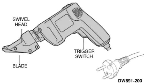
To start tool, depress trigger switch. To stop tool, release the trigger. To lock the trigger in the on position for continuous operation, depress trigger, push up the lock button (Figure 1), and gently release the trigger. To release the locking mechanism, depress the trigger fully, then release it. Before using the tool each time, be sure that the lock button release mechanism is working freely. Be sure to release the switch lock button before disconnecting the plug from the power supply. Failure to do so will cause the tool to start immediately the next time it is plugged in. Damage or injury could result. The variable speed trigger switch permits speed control. The farther the trigger is depressed, the higher the speed of the shear.
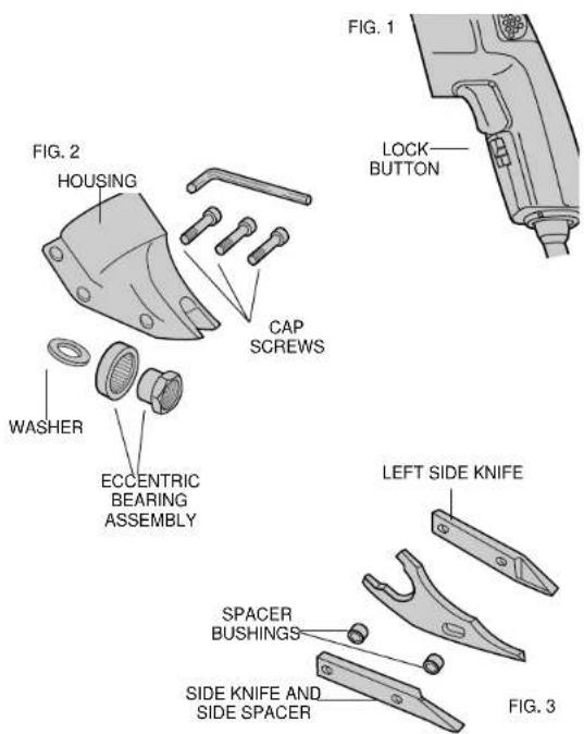
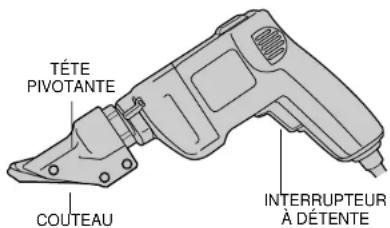
Disassembly and Assembly (Figures 2 and 3)
To remove shear head from motor, loosen 3 cap screws. Remove shear head by pulling head firmly forward. Slight twisting action may be required if head does not slide off easily.
To remove cutter blades from shear head, remove 3 cap screws from shear housing. Be careful not to lose rear spacer bushing when removing middle cap screw. Remove center blade from housing by tapping blade gently towards the rear. Side knife and side spacer will now drop out of the housing.
To remove eccentric bearing assembly from shaft, use an appropriate wrench to loosen eccentric nut by turning counterclockwise.
To install eccentric bearing assembly onto shaft, make sure the large thin washer is first inserted over shaft. Screw eccentric bearing assembly onto shaft and tighten with appropriate wrench. Lubricate bearing with a good grade of bearing grease.
To install cutter blades into shear housing, place the side knife and side spacer into position in the shear housing. Insert center cap screw through side knife and side spacer with rear spacer bushing between them. Start cap screw into thread just enough to hold blades in place. DO NOT TIGHTEN. Insert spacer bushing into hole in center blade and lubricate. Install center blade into shear housing by tapping blade gently forward using a drift to line up hole in center blade with forward holes in housing. Insert and tighten forward cap screw making sure spacer bushing in center blade stays in position. Apply good grade of bearing grease to clevis or yoke in center blade where it rides on the eccentric bearing assembly. Insert rear cap screw into shear housing but do not completely tighten.
To install shear head assembly onto drive motor, make sure all cap screws are loosened about 3 or 4 complete turns. Place shear head onto unit and alternately tighten cap screws snugly to lock head assembly in place. It may be necessary to gently tap the shear head into place if it does not readily slip onto the nose of the power unit.
Operation
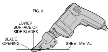
For accurate work, always clamp or anchor the material to be cut.
Line up one edge of the tool's middle blade with the cutting line and advance blades into the material without forced effort or unnecessary pressure. A little practice will enable you to determine what forward pressure gives you the smoothest cutting. It is important to keep the lower surfaces of the side blades flat on the material being cut (Figure 4). When cutting curves, do not tilt the tool; keep the side blades flat and level. For best cutting efficiency, keep blades sharp. Wear gloves when handling sheet metal. The edges are sharp and can cause injury.
⚠️ CAUTION: Do not use the shear with any kind of accessory or attachment. Such usage might be hazardous.
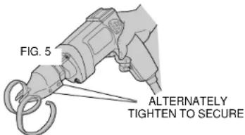
Adjustment (Figure 5)
To adjust the curl of waste material, the left side knife has elongated holes. Adjustment may be necessary after changing blades or material being cut. Loosen cap screws and tap side knife either forward or backward so that curl of waste does not hit shear housing or work material while cutting.
Lubrication
All ball bearings are factory lubricated to last the life of the tool. All sleeve and needle bearings receive their lubrication from grease in the gear case. Clean and re-lubricate gear case yearly or whenever
servicing requires the gear case to be removed. Use type and quantity of grease shown on the parts bulletin packed with your tool.
Accessories
Recommended accessories for use with your tool are available at extra cost from your distributor or local service center.
⚠️ CAUTION: The use of any non-recommended accessory may be hazardous.
Important
To assure product SAFETY and RELIABILITY, repairs, maintenance and adjustment (including brush inspection and replacement) should be performed by authorized service centers or other qualified service organizations, always using identical replacement parts.
Full Warranty
DeWALT heavy duty industrial tools are warranted for one year from date of purchase. We will repair, without charge, any defects due to faulty materials or workmanship. For warranty repair information, call 1-800-4-DeWALT. This warranty does not apply to accessories or damage caused where repairs have been made or attempted by others. This warranty gives you specific legal rights and you may have other rights which vary in certain states or provinces. In addition to the warranty, DeWALT tools are covered by our:
30 DAY NO RISK SATISFACTION GUARANTEE
If you are not completely satisfied with the performance of your D=WALT heavy duty industrial tool, simply return it to the participating seller within 30 days for a full refund. Please return the complete unit, transportation prepaid. Proof of purchase may be required.
POUR TOUT RENSEIGNEMENT SUPPLÉMENTAIRE SUR CET OUTIL OU TOUT AUTRE OUTIL DEWALT, COMPOSER SANS FRAIS LE NUMÉRO:
1 800 4-DEWALT (1 800 433-9258)
IMPORTANTES MESURES DE SÉCURITÉ (POUR TOUS LES OUTILS)
25 ft. 50 ft. 75 ft. 100 ft. 125 ft. 150 ft. 175 ft.
7,6 m 15.2 m 22.9 m 30.5 m 38.1 m 45.7 m 53.3 m
Intensité
18 AWG 18 AWG 16 AWG 16 AWG 14 AWG 14 AWG 12 AWG