DCS498 - Scissors DEWALT - Free user manual and instructions
Find the device manual for free DCS498 DEWALT in PDF.

| Product Type | Fiber Cement Panel Shear |
| Brand | DeWalt |
| Model | DCS498 |
| Maximum Cutting Capacity | 15.8 mm (5/8 in) |
| Cutting Width (Kerf Width) | 6.35 mm (1/4 in) |
| Minimum Curve Radius | 175 mm (7 in) |
| Power Source | 20 V max Lithium-Ion Battery Pack |
| Recommended Charger Type | DEWALT Charger (model DCB118) |
| Variable Speed | Yes, via variable speed trigger |
| Switch Lock | On/Lock control button |
| Weight (without battery pack) | Approximately 2.5 kg |
| Materials Cut | Cement panels and exterior siding |
| Usage | Professional |
| Warranty | 3 years limited (parts and labor) |
| Maintenance | Clean with dry compressed air; annual lubrication at an authorized service center |
| Required Safety | Safety glasses (ANSI Z87.1), hearing protection (ANSI S12.6), dust mask |
| Main Replacement Parts | Side and center blades, eccentric bearing, spacer shims |
| Repairability | Repairs only by DEWALT authorized service center |
Frequently Asked Questions - DCS498 DEWALT
User questions about DCS498 DEWALT
0 question about this device. Answer the ones you know or ask your own.
Ask a new question about this device
Download the instructions for your Scissors in PDF format for free! Find your manual DCS498 - DEWALT and take your electronic device back in hand. On this page are published all the documents necessary for the use of your device. DCS498 by DEWALT.
USER MANUAL DCS498 DEWALT
Definitions: Safety Alert Symbols and Words
This instruction manual uses the following safety alert symbols and words to alert you to hazardous situations and your risk of personal injury or property damage.
D. IGER: Indicates an imminently hazardous situation which, if not avoided, will result in death or serious injury.
WINDING: Indicates a potentially hazardous situation which, if not avoided, could result in death or serious injury.
CAITON: Indicates a potentially hazardous situation which, if not avoided, may result in minor or moderate injury.
(without word) Indicates a safety related message.
NOTICE: Indicates a practice not related to personal injury which, if not avoided, may result in property damage.
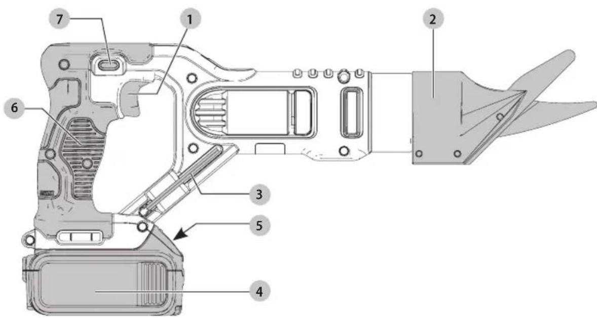
Fig. A
1 Trigger switch/variable speed switch
2 Shear head assembly
3 Hex wrench
4 Battery
5 Battery release button
6 Main handle
7 On/Lock-off control button
WARNING! Read all safety warnings and all
Instructions. Failure to follow the warnings and instructions may result in electric shock, fire and/or serious injury.

WARNING: To reduce the risk of injury, read the
instruction manual.
If you have any questions or comments about this or any DEWALT tool, call us toll free at:
1-800-4-DEWALT(1-800-433-9258).
English
GENERAL POWER TOOL SAFETY WARNINGS
WARNING! Read all safety warnings and all instructions. Failure to follow the warnings and instructions may result in electric shock, fire and/or serious injury.
SAVE ALL WARNING AND INSTRUCTIONS FOR FUTURE REFERENCE
The term "power tool" in the warnings refers to your mains-operated (corded) power tool or battery-operated (cordless) power tool.
1) Work Area Safety
a) Keep work area clean and well lit. Cluttered or dark areas invite accidents.
b) Do not operate power tools in explosive atmospheres, such as in the presence of flammable liquids, gases or dust. Power tools create sparks which may ignite the dust or fumes.
c) Keep children and bystanders away while operating a power tool. Distractions can cause you to lose control.
2) Electrical Safety
a) Power tool plugs must match the outlet. Never modify the plug in any way. Do not use any adapter plugs with earthed (grounded) power tools. Unmodified plugs and matching outlets will reduce risk of electric shock.
b) Avoid body contact with earthed or grounded surfaces such as pipes, radiators, ranges and refrigerators. There is an increased risk of electric shock if your body is earthed or grounded.
c) Do not expose power tools to rain or wet conditions. Water entering a power tool will increase the risk of electric shock.
d) Do not abuse the cord. Never use the cord for carrying, pulling or unplugging the power tool. Keep cord away from heat, oil, sharp edges or moving parts. Damaged or entangled cords increase the risk of electric shock.
e) When operating a power tool outdoors, use an extension cord suitable for outdoor use. Use of a cord suitable for outdoor use reduces the risk of electric shock.
f) If operating a power tool in a damp location is unavoidable, use a ground fault circuit interrupter (GFCI) protected supply. Use of a GFCI reduces the risk of electric shock.
3) Personal Safety
a) Stay alert, watch what you are doing and use common sense when operating a power tool. Do not use a power tool while you are tired or under the influence of drugs, alcohol or medication. A moment of inattention while operating power tools may result in serious personal injury.
b) Use personal protective equipment. Always wear eye protection. Protective equipment such as dust mask, non-skid safety shoes, hard hat, or hearing protection used for appropriate conditions will reduce personal injuries.
c) Prevent unintentional starting. Ensure the switch is in the off position before connecting to power source and/or battery pack, picking up or carrying the tool. Carrying power tools with your finger on the switch or energizing power tools that have the switch on invites accidents.
d) Remove any adjusting key or wrench before turning the power tool on. A wrench or a key left attached to a rotating part of the power tool may result in personal injury.
e) Do not overreach. Keep proper footing and balance at all times. This enables better control of the power tool in unexpected situations.
f) Dress properly. Do not wear loose clothing or jewelry. Keep your hair, clothing and gloves away from moving parts. Loose clothes, jewelry or long hair can be caught in moving parts.
g) If devices are provided for the connection of dust extraction and collection facilities, ensure these are connected and properly used. Use of dust collection can reduce dust-related hazards.
4) Power Tool Use and Care
a) Do not force the power tool. Use the correct power tool for your application. The correct power tool will do the job better and safer at the rate for which it was designed.
b) Do not use the power tool if the switch does not turn it on and off. Any power tool that cannot be controlled with the switch is dangerous and must be repaired.
c) Disconnect the plug from the power source and/or the battery pack from the power tool before making any adjustments, changing accessories, or storing power tools. Such preventive safety measures reduce the risk of starting the power tool accidentally.
d) Store idle power tools out of the reach of children and do not allow persons unfamiliar with the power tool or these instructions to operate the power tool. Power tools are dangerous in the hands of untrained users.
e) Maintain power tools. Check for misalignment or binding of moving parts, breakage of parts and any other condition that may affect the power tool's operation. If damaged, have the power tool repaired before use. Many accidents are caused by poorly maintained power tools.
f) Keep cutting tools sharp and clean. Properly maintained cutting tools with sharp cutting edges are less likely to bind and are easier to control.
g) Use the power tool, accessories and tool bits, etc. in accordance with these instructions, taking
into account the working conditions and the work to be performed. Use of the power tool for operations different from those intended could result in a hazardous situation.
5) Battery Tool Use and Care
a) Recharge only with the charger specified by the manufacturer. A charger that is suitable for one type of battery pack may create a risk of fire when used with another battery pack.
b) Use power tools only with specifically designated battery packs. Use of any other battery packs may create a risk of injury and fire.
c) When battery pack is not in use, keep it away from other metal objects, like paper clips, coins, keys, nails, screws, or other small metal objects, that can make a connection from one terminal to another. Shorting the battery terminals together may cause burns or a fire.
d) Under abusive conditions, liquid may be ejected from the battery; avoid contact. If contact accidentally occurs, flush with water. If liquid contacts eyes, additionally seek medical help. Liquid ejected from the battery may cause irritation or burns.
6) Service
a) Have your power tool serviced by a qualified repair person using only identical replacement parts. This will ensure that the safety of the power tool is maintained.
Additional Specific Safety Instructions for Shears
- Hold power tools by insulated gripping surfaces when performing an operation where the cutting tool may contact hidden wiring or its own cord.
Contacting a "live" wire may make exposed metal parts of the tool "live" and shock the operator. - Cut material at or below rated capacity. The unit is capable of cutting up to 5/8'' (15.8 mm) fiber cement board.
NEVER have any part of your body near the blades. Serious personal injury may result. - Keep hands away from cutting area. A moment of inattention while operating power tools may result in serious personal injury.
- Stay clear of end pieces that may fall after being cut off. Contact with a sharp edge could result in personal injury.
- Keep all screws tight. Check periodically for loosening.
- Clean out your tool often, especially after heavy use. Dust and grit often accumulate on interior surfaces and could lead to tool failure.
Additional Safety Information
WARNING: ALWAYS use safety glasses. Everyday glasses are NOT safety glasses. Also use face or
English
dust mask if cutting operation is dusty. ALWAYS WEAR CERTIFIED SAFETY EQUIPMENT:
ANSI Z87.1 eye protection (CAN/CSA Z94.3)
ANSI S12.6 (S3.19) hearing protection,
- NIOSH/OSHA/MSHA respiratory protection.
WARNING: Some dust created by power sanding, grinding, grinding, and other construction activities contains chemicals known to the State of California to cause cancer, birth defects or other reproductive harm. Some examples of these chemicals are:
- lead from lead-based paints,
crystalline silica from bricks and cement and other masonry products, and
arsenic and chromium from chemically-treated lumber.
Your risk from these exposures varies, depending on how often you do this type of work. To reduce your exposure to these chemicals: work in a well ventilated area, and work with approved safety equipment, such as those dust masks that are specially designed to filter out microscopic particles.
- Avoid prolonged contact with dust from power sanding, sawing, grinding, drilling, and other construction activities. Wear protective clothing and wash exposed areas with soap and water. Allowing dust to get into your mouth, eyes, or lay on the skin may promote absorption of harmful chemicals.
WARNING: Use of this tool can generate and/ or disperse dust, which may cause serious and permanent respiratory or other injury. Always use NIOSH/OSHA approved respiratory protection appropriate for the dust exposure. Direct particles away from face and body.
WARNING: Always wear proper personal hearing protection that conforms to ANSI S12.6 (S3.19)
during use. Under some conditions and duration of use, noise from this product may contribute to hearing loss.
CAITION: When not in use, place tool on its side table surface where it will not cause a
stripping or falling hazard. Some tools with large battery packs will stand upright on the battery pack but may be easily knocked over.
Air vents often cover moving parts and should be avoided. Loose clothes, jewelry or long hair can be caught in moving parts.
The label on your tool may include the following symbols. The symbols and their definitions are as follows:
V. voltts IPM. .impacts per minute
Hz.....hertz RPM... revolutionspers
min.. minutes minute
-- or DC....direct current sfpm surface feet per Class I Construction minute
(grounded)
.../min..per minute A. amperes
BPM... .beats per minute W... .watts
ENGLISH
or AC....alternating current
or AC/DC....alternatingordirect current
A visible radiation
wearrespiratory protection
Classll Construction (double insulated)
weareye protection
O............wearhearing protection
no load speed n..rated speed
readall documentation
earthing terminal
A . safety alert symbol
BATTERIES AND CHARGERS
The battery pack is not fully charged out of the carton. Before using the battery pack and charger, read the safety instructions below and then follow charging procedures outlined. When ordering replacement battery packs, be sure to include the catalog number and voltage. Your tool uses a DEWALT charger. Be sure to read all safety instructions before using your charger. Consult the chart at the end of this manual for compatibility of chargers and battery packs.
READ ALL INSTRUCTIONS
Important Safety Instructions for All Battery Packs
WARNING: Read all safety warnings and all instructions for the battery pack, charger and power tool. Failure to follow the warnings and instructions may result in electric shock, fire and/or serious injury.
- Do not charge or use the battery pack in explosive atmospheres, such as in the presence of flammable liquids, gases or dust. Inserting or removing the battery pack from the charger may ignite the dust or fumes.
- NEVER force the battery pack into the charger. DO NOT modify the battery pack in any way to fit into a non-compatible charger as battery pack may rupture causing serious personal injury. Consult the chart at the end of this manual for compatibility of batteries and chargers.
- Charge the battery packs only in designated DEWALT chargers.
DO NOT splash or immerse in water or other liquids. - Do not store or use the tool and battery pack in locations where the temperature may reach or exceed 104^ ( 40^ ) (such as outside sheds or metal buildings in summer). For best life store battery packs in a cool, dry location.
NOTE: Do not store the battery packs in a tool with the trigger switch locked on. Never tape the trigger switch in the ON position.
-
Do not incinerate the battery pack even if it is severely damaged or is completely worn out. The battery pack can explode in a fire. Toxic fumes and materials are created when lithium ion battery packs are burned.
-
If battery contents come into contact with the skin, immediately wash area with mild soap and water. If battery liquid gets into the eye, rinse water over the open eye for 15 minutes or until irritation ceases. If medical attention is needed, the battery electrolyte is composed of a mixture of liquid organic carbonates and lithium salts.
-
Contents of opened battery cells may cause respiratory irritation. Provide fresh air. If symptoms persist, seek medical attention.
WARNING: Burn hazard. Battery liquid may be
WARNING: Fire hazard. Never attempt to open the battery pack for any reason. If the battery pack case is cracked or damaged, do not insert into the charger. Do not crush, drop or damage the battery pack. Do not use a battery pack or charger that has received a sharp blow, been dropped, run over or damaged in any way (e.g., pierced with a nail, hit with a hammer, stepped on). Damaged battery packs should be returned to the service center for recycling.
Transportation
WARNING: Fire hazard. Do not store or carry the battery pack so that metal objects can contact exposed battery terminals. For example, do not place the battery pack in aprons, pockets, tool boxes, product kit boxes, drawers, etc., with loose nails, screws, keys, etc. Transporting batteries can possibly cause fires if the battery terminals inadvertently come in contact with conductive materials such as keys, coins, hand tools and the like. The US Department of Transportation Hazardous Material Regulations (HMR) actually prohibit transporting batteries in commerce or on airplanes in carry-on baggage UNLESS they are properly protected from short circuits. So when transporting individual battery packs, make sure that the battery terminals are protected and well insulated from materials that could contact them and cause a short circuit.
Shipping the DEWALT FLEXVOLT™ Battery
The DFWALT FLEXVOLT™ battery has two modes: Use and Shipping.
Use Mode: When the FLEXVOLT™ battery stands alone or is in a DEWALT 20V Max product, it will operate as a 20V Max battery. When the FLEXVOLT™ battery is in a 60V Max or a 120V Max (two 60V Max batteries) product, it will operate as a 60V Max battery.
Shipping Mode: When the cap is attached to the FLEXVOLT™ battery, the battery is in Shipping Mode. Strings of cells are electrically
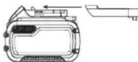
disconnected within the pack resulting in three batteries with a lower Watt hour (Wh) rating as compared to one battery with a higher Watt hour rating. This increased quantity of three batteries with the lower Watt hour rating can exempt the pack from certain shipping regulations that are imposed upon the higher Watt hour batteries.
English
The battery label indicates two Watt hour ratings (see example). Depending on how the battery is shipped, the appropriate Watt hour rating must be used to determine the applicable shipping requirements. If utilizing the shipping cap, the pack will be considered 3 batteries at the Watt hour rating indicated for "Shipping". If shipping without the cap or in a tool, the pack will be considered one battery at the Watt hour rating indicated next to "Use".
Example of Use and Shipping Label Marking
USE: 120 Wh Shipping: 3 × 40 Wh
For example, Shipping Wh rating might indicate 3 x 40 Wh, meaning 3 batteries of 40 Watt hours each. The Use Wh rating might indicate 120 Wh (1 battery implied).
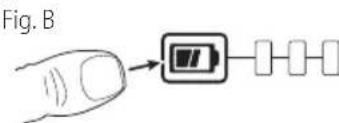
Fuel Gauge Battery Packs (Fig. B)
Some DEWALT battery packs include a fuel gauge which consists of three green LED lights that indicate the level of charge remaining in the battery pack.
The fuel gauge is an indication of approximate levels of charge remaining in the battery pack according to the following indicators:

75-100% charged

51-74% charged

< 50% charged

Pack needs to be charged
To actuate the fuel gauge, press and hold the fuel gauge button. A combination of the three green LED lights will illuminate designating the level of charge left. When the level of charge in the battery is below the usable limit, the fuel gauge will not illuminate and the battery will need to be recharged.
NOTE: The fuel gauge is only an indication of the charge left on the battery pack. It does not indicate tool functionality and is subject to variation based on product components, temperature and end-user application.
For more information regarding fuel gauge battery packs, please contact call 1-800-4-DEWALT (1-800-433-9258) or visit our website www.dewalt.com.
The RBRC Seal
The RBRC* (Rechargeable Battery Recycling Corporation) Seal on the nickel cadmium, nickel metal hydride or lithium-ion batteries (or battery packs) indicates that the costs to recycle these

batteries (or battery packs) at the end of their useful life have already been paid by DEWALT. In some areas, it is illegal to place spent nickel cadmium, nickel metal hydride or lithium-ion batteries in the trash or municipal solid
waste stream and the Call 2 Recycle® program provides an environmentally conscious alternative.
Call 2 Recycle, Inc., in cooperation with DEWALT and other battery users, has established the program in the United States and Canada to facilitate the collection of spent nickel cadmium, nickel metal hydride or lithium-ion batteries. Help protect our environment and conserve natural resources by returning the spent nickel cadmium, nickel metal hydride or lithium-ion batteries to an authorized DEWALT service center or to your local retailer for recycling. You may also contact your local recycling center for information on where to drop off the spent battery. RBRC is a registered trademark of Call 2 Recycle, Inc.
Important Safety Instructions for All Battery Chargers
WARNING: Read all safety warnings and all instructions for the battery pack, charger and power tool. Failure to follow the warnings and instructions may result in electric shock, fire and/or serious injury.
DO NOT attempt to charge the battery pack with any chargers other than the ones in this manual.
The charger and battery pack are specifically designed to work together.
- These chargers are not intended for any uses other than charging DEWALT rechargeable batteries.
Any other uses may result in risk of fire, electric shock or electrocution.
-
Do not expose the charger to rain or snow.
-
Pull by the plug rather than the cord when
disconnecting the charger. This will reduce the risk of damage to the electric plug and cord.
-
Make sure that the cord is located so that it will not be stepped on, tripped over or otherwise subjected to damage or stress.
-
Do not use an extension cord unless it is absolutely necessary. Use of improper extension cord could result in risk of fire, electric shock or electrocution.
-
When operating a charger outdoors, always provide a dry location and use an extension cord suitable for outdoor use. Use of a cord suitable for outdoor use reduces the risk of electric shock.
-
An extension cord must have adequate wire size (AWG or American Wire Gauge) for safety. The smaller the gauge number of the wire, the greater the capacity of the cable, that is, 16 gauge has more capacity than 18 gauge. An undersized cord will cause a drop in line voltage resulting in loss of power and overheating. When using more than one extension to make up the total length, be sure each individual extension contains at least the minimum wire size. The following table shows the correct size to use depending on cord length and nameplate ampere rating. If in doubt, use the next heavier gauge. The lower the gauge number, the heavier the cord.
ENGLISH
Minimum Gauge for Cord Sets
| Volts | Total Length of Cord in Feet(meters) | ||||
| 120 V 25 (7.6) | 50 (15.2) | 100 (30.5) | 150 (45.7) | ||
| 240 V 50 (15.2) | 100 (30.5) | 200 (61.0) | 300 (91.4) | ||
| Ampere Rating | American Wire Gauge | ||||
| More Than | Not More Than | ||||
| 0 6 18 | 16 16 14 | ||||
| 6 10 | 18 16 14 12 | ||||
| 10 12 | 16 16 14 12 | ||||
| 12 16 | 14 12 Not Recommended | ||||
- Do not place any object on top of the charger or place the charger on a soft surface that might block the ventilation slots and result in excessive internal heat. Place the charger in a position away from any heat source. The charger is ventilated through slots in the top and the bottom of the housing.
- Do not operate the charger with a damaged cord or plug.
- Do not operate the charger if it has received a sharp blow, been dropped or otherwise damaged in any way. Take it to an authorized service center.
- Do not disassemble the charger; take it to an authorized service center when service or repair is required. Incorrect reassembly may result in a risk of electric shock, electrocution or fire.
- Disconnect the charger from the outlet before attempting any cleaning. This will reduce the risk of electric shock. Removing the battery pack will not reduce this risk.
NEVER attempt to connect 2 chargers together.
The charger is designed to operate on standard 120V household electrical power. Do not attempt to use it on any other voltage. This does not apply to the vehicular charger.
WARNING: Shock hazard. Do not allow any liquid to side the charger. Electric shock may result.
WARNING: Burn hazard. Do not submerge the battery pack in any liquid or allow any liquid to enter the battery pack. Never attempt to open the battery pack for any reason. If the plastic housing of the battery pack breaks or cracks, return to a service center for recycling.
CAUTION: Burn hazard. To reduce the risk of injury, charge only DEWALT rechargeable battery packs. Other types of batteries may overheat and burst resulting in personal injury and property damage.
NOTICE: Under certain conditions, with the charger plugged into the power supply, the charger can be shorted by foreign material. Foreign materials of a conductive nature, such as, but not limited to, grinding dust, metal chips, steel wool, aluminum foil or any buildup of metallic particles should be kept away from the charger cavities. Always unplug the charger from the power supply when there is no
battery pack in the cavity. Unplug the charger before attempting to clean.
Charging a Battery (Fig. C)
- Plug the charger into an appropriate outlet before inserting battery pack.
Fig. C
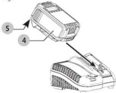
- Insert the battery pack 4 into the charger, making sure the battery pack is fully seated in the charger. The red (charging) light will blink continuously indicating that the charging process has started.
- The completion of charge will be indicated by the red light remaining ON continuously. The battery pack is fully charged and may be used at this time or left in the charger. To remove the battery pack from the charger, push the battery release button 5 on the battery pack.
NOTE: To ensure maximum performance and life of lithium-ion battery packs, charge the battery pack fully before first use.
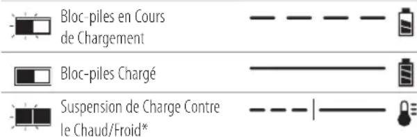
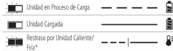
Charger Operation
Refer to the indicators below for the charge status of the battery pack.
| DCB107, DCB112, DCB113, DCB115, DCB118, DCB132 | |
| Charging | - - - - - |
| Fully Charged | - - - - - |
| Hot/Cold Pack Delay* | - - - - - |
- DCB107, DCB112, DCB113, DCB115, DCB118, DCB132: The red light will continue to blink, but a yellow indicator light will be illuminated during this operation. Once the battery pack has reached an appropriate temperature, the yellow light will turn off and the charger will resume the charging procedure.
The compatible charger(s) will not charge a faulty battery pack. The charger will indicate faulty battery pack by refusing to light or by displaying a problem pack or charger blink pattern.
NOTE: This could also mean a problem with a charger. If the charger indicates a problem, take the charger and battery pack to be tested at an authorized service center.
Hot/Cold Pack Delay
When the charger detects a battery pack that is too hot or too cold, it automatically starts a Hot/Cold Pack Delay, suspending charging until the battery pack has reached an appropriate temperature. The charger then automatically
English
switches to the pack charging mode. This feature ensures maximum battery pack life.
A cold battery pack will charge at a slower rate than a warm battery pack. The battery pack will charge at that slower rate throughout the entire charging cycle and will not return to maximum charge rate even if the battery pack warms.
The DCB118 charger is equipped with an internal fan designed to cool the battery pack. The fan will turn on automatically when the battery pack needs to be cooled.
Never operate the charger if the fan does not operate properly or if ventilation slots are blocked. Do not permit foreign objects to enter the interior of the charger.
Electronic Protection System
Li-Ion tools are designed with an Electronic Protection System that will protect the battery pack against overloading, overheating or deep discharge.
The tool will automatically turn off if the Electronic Protection System engages. If this occurs, place the lithium-ion battery pack on the charger until it is fully charged.
Wall Mounting
DCB107, DCB112, DCB113, DCB115, DCB118, DCB132
These chargers are designed to be wall mountable or to sit upright on a table or work surface. If wall mounting, locate the charger within reach of an electrical outlet, and away from a corner or other obstructions which may impede air flow. Use the back of the charger as a template for the location of the mounting screws on the wall. Mount the charger securely using drywall screws (purchased separately) at least 1^ (25.4 mm) long, with a screw head diameter of 0.28-0.35" (7-9 mm), screwed into wood to an optimal depth leaving approximately 7/32" (5.5 mm) of the screw exposed. Align the slots on the back of the charger with the exposed screws and fully engage them in the slots.
Charger Cleaning Instructions
WARNING: Shock hazard. Disconnect the charger from the AC outlet before cleaning. Dirt and grease may be removed from the exterior of the charger using a cloth or soft non-metallic brush. Do not use water or any cleaning solutions.
Important Charging Notes
- Longest life and best performance can be obtained if the battery pack is charged when the air temperature is between 65^ and 75^ (18^ - 24^) . DO NOT charge the battery pack in an air temperature below +40^ (+4.5^) , or above +104^ (+40^) . This is important and will prevent serious damage to the battery pack.
- The charger and battery pack may become warm to the touch while charging. This is a normal condition, and does not indicate a problem. To facilitate the cooling of the battery pack after use, avoid placing the charger or battery pack in a warm environment such as in a metal shed or an uninsulated trailer.
- If the battery pack does not charge properly:
a. Check operation of receptacle by plugging in a lamp or other appliance;
b. Check to see if receptacle is connected to a light switch which turns power off when you turn out the lights;
c. Move the charger and battery pack to a location where the surrounding air temperature is approximately 65^ - 75^ (18^ - 24^) ;
d. If charging problems persist, take the tool, battery pack and charger to your local service center.
- The battery pack should be recharged when it fails to produce sufficient power on jobs which were easily done previously. DO NOT CONTINUE to use under these conditions. Follow the charging procedure. You may also charge a partially used pack whenever you desire with no adverse effect on the battery pack.
- Foreign materials of a conductive nature such as, but not limited to, grinding dust, metal chips, steel wool, aluminum foil, or any buildup of metallic particles should be kept away from charger cavities. Always unplug the charger from the power supply when there is no battery pack in the cavity. Unplug the charger before attempting to clean.
- Do not freeze or immerse the charger in water or any other liquid.
Storage Recommendations
- The best storage place is one that is cool and dry, away from direct sunlight and excess heat or cold.
- For long storage, it is recommended to store a fully charged battery pack in a cool dry place out of the charger for optimal results.
NOTE: Battery packs should not be stored completely depleted of charge. The battery pack will need to be recharged before use.
SAVE THESE INSTRUCTIONS FOR FUTURE USE
COMPONENTS (FIG. A)
WARNING: Never modify the power tool or any part of it. Damage or personal injury could result.
Refer to Figure A at the beginning of this manual for a complete list of components.
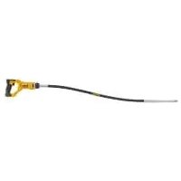
Intended Use
The DCS498 5/8" (15.8 mm) fiber-cement siding shear is designed for cutting cement board/siding. You can make both straight and curved cuts with a minimum radius of 7" (175 mm). The shear removes a 1/4" (6.35 mm) wide piece of waste material
DO not use under wet conditions or in presence of flammable liquids or gases.
This fiber-cement siding shear is a professional power tool.
DO nOT let children come into contact with the tool.
Supervision is required when inexperienced operators use this tool.
English
ASSEMBLY AND ADJUSTMENTS
WARNING: To reduce the risk of serious personal injury, turn unit off and remove the battery pack before making any adjustments or removing/ installing attachments or accessories. An accidental start-up can cause injury.
Remove and Replace Parts (Fig. D, E) Removing the Shear Head Assembly (Fig. D)
- To remove shear head assembly 2 from motor, loosen 3 cap screws 10.
- Remove shear head assembly by pulling head firmly forward. Slight twisting action may be required if head does not slide off easily.
Removing the Cutter Blades (Fig. D, E)
- To remove cutter blades from shear head assembly, remove 3 cap screws 10 from shear housing with the provided hex wrench 3 . Be careful not to lose rear spacer bushing when removing middle cap screw.
- Remove center blade 13 from housing by tapping blade gently towards the rear. Side knife 12 and side spacers 9 will now drop out of the housing.
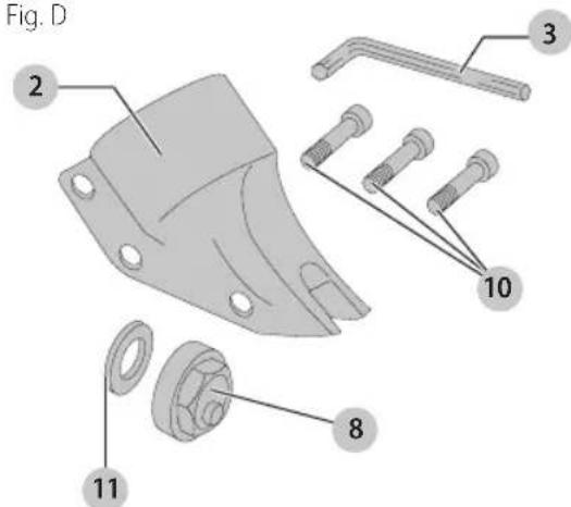
Removing and Replacing the Eccentric Bearing Assembly (Fig. D)
To remove eccentric bearing assembly from shaft, use an appropriate wrench to loosen eccentric nut 8 by turning counterclockwise.
- To install eccentric bearing assembly onto shaft, make sure the large thin washer 11 is first inserted over shaft.
- Screw eccentric bearing assembly onto shaft and tighten with appropriate wrench.
- Lubricate eccentric nut 8 with a good grade of bearing grease.
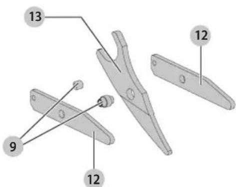
Fig. E
Installing the Cutter Blades (Fig. D, E)
- To install cutter blades into shear housing, place the side knife 12 and side spacer 9 into position in the shear head assembly 2.
- Insert center cap screws 10 through side knife and side spacer with rear spacer pushing between them.
- Start cap screw into thread just enough to hold blades in place. DO NOT TIGHTEN.
- Insert side spacers 9 into hole in center blade 13 and lubricate.
- Install center blade into shear housing by tapping blade gently forward using a drift to line up hole in center blade with forward holes in housing. Insert and tighten forward cap screw making sure spacer bushing in center blade stays in position.
- Apply good grade of bearing grease to clevis or yoke in center blade where it rides on the eccentric bearing assembly. Insert rear cap screw into shear housing but do not completely tighten.
nOTE: Change the side knives after they show a width wear pattern of 50% . Swap the knives left to right and use them until the patterns meet. When the patterns meet, invert the left and right side knives and use them until they show a width wear pattern of 50% . They can then be swapped from left to right until you use all 4 sides of the blades. Never exceed 10000 feet of cutting on a set of side knives. The tool will continue to cut after these landmarks are reached, but the power unit will become overloaded.
Installing the Shear Head Assembly (Fig. D)
- To install shear head assembly 2 onto drive motor, make sure all cap screws 10 are loosened about 3 or 4 complete turns.
- Place shear head onto unit and alternately tighten cap screws snugly to lock head assembly in place. It may be necessary to gently tap the shear head into place if it does not readily slip onto the nose of the power unit.
- Tighten all three cap screws to 45-50 in-lbs. (5.08-5.64 Nm). Failure to tighten the cap screws properly can cause the cap screws to break.
OPERATION
WARNING: To reduce the risk of serious personal injury, turn unit off and remove the battery pack before making any adjustments or removing/ installing attachments or accessories. An accidental start-up can cause injury.
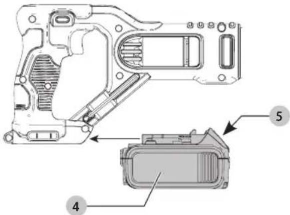
Installing and Removing the Battery Pack (Fig. F)
NOTE: For best results, make sure your battery pack is fully charged.
To install the battery pack 4 into the tool handle, align the battery pack with the rails inside the tool's handle and slide it into the handle until the battery pack is firmly seated in the tool and ensure that it does not disengage.
To remove the battery pack from the tool, press the release button 5 and firmly pull the battery pack out of the tool handle. Insert it into the charger as described in the charger section of this manual.
Fig. F
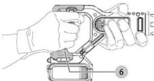
Proper Hand Position (Fig. G)
WARNING: To reduce the risk of serious personal injury, AYs use proper hand position as shown.
WARNING: To reduce the risk of serious personal injury, ALWAYS hold securely in anticipation of a sudden reaction.
WARNING: Cut Hazard. NEVER have any part of your body near the blades. Serious personal injury may occur.
Proper hand position requires one hand on the handle 6 and one hand on the tool body.
Fig. G
Variable Speed Switch (Fig. H)
To turn the tool ON, squeeze the trigger switch 1. To turn the tool OFF release the trigger.
Your tool is equipped with a variable speed switch which enables you to select the best speed for a particular application. The farther you squeeze the trigger, the faster the tool will operate. Use lower speeds for cutting tight curves or following precise guideline. Higher speeds are better for gradual curves and straight line cuts. For maximum tool life, use lower speeds only for short periods of time.
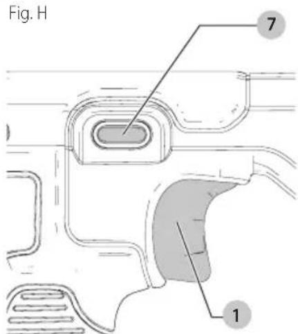
On/Lock-Off Control Button (Fig. H)
An On/Lock-Off control button 7 serves as a lock-off button. To select the ON position, release the trigger switch and depress the control button on the right side of the tool, as shown in Figure H. To select Locked/OFF, depress the control button on the left side of the tool. When changing the position of the control button, be sure the trigger is released.
Shearing (Fig. 1)
CAITION: Risk of personal injury or damage tool. Do not use the shear with any kind of accessory or attachment.
- For accurate work, always clamp or anchor the material to be cut.
- Line up one edge of the tool's middle blade with the cutting line and advance blades into the material without forced effort or unnecessary pressure.
- A little practice will enable you to determine what forward pressure gives you the smoothest cutting.
It is important to keep the lower surfaces of the side blades flat on the material being cut (Fig. 1). - When cutting curves, do not tilt the tool; keep the side blades flat and level. For best cutting efficiency, keep blades sharp.
English
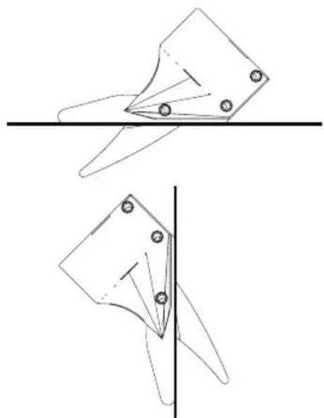
Fig.1
MAINTENANCE
WARNING: To reduce the risk of serious personal injury, turn unit off and remove the battery pack before making any adjustments or removing/ installing attachments or accessories. An accidental start-up can cause injury.
Lubrication
Self lubricating bearings are used in the tool and periodic relubrication is not required. However, it is recommended that, once a year, you take or send the tool to a service center for a thorough cleaning and inspection.
Cleaning
WARNING: Blow dirt and dust out of all air vents with clean, dry air at least once a week. To minimize the risk of eye injury, always wear ANSI Z87.1 approved eye protection when performing this.
WARNING: Never use solvents or other harsh chemicals for cleaning the non-metallic parts of the tool. These chemicals may weaken the plastic materials used in these parts. Use a cloth dampened only with water and mild soap. Never let any liquid get inside the tool; never immerse any part of the tool into a liquid.
Accessories
WARNING: Since accessories, other than those used by DEWALT, have not been tested with this product, use of such accessories with this tool could be hazardous. To reduce the risk of injury, only DEWALT recommended accessories should be used with this product.
Recommended accessories for use with your tool are available at extra cost from your local dealer or authorized service center. If you need assistance in locating any accessory, please contact DEWALT Industrial Tool Co., 701 East Joppa Road, Towson, MD 21286, call 1-800-4-DEWALT (1-800-433-9258) or visit our website: www.dewalt.com.
Repairs
The charger and battery pack are not serviceable.
WARNING: To assure product SAFETY and BILITIES, repairs, maintenance and adjustment (including brush inspection and replacement, when applicable) should be performed by a DEWALT factory service center or a DEWALT authorized service center. Always use identical replacement parts.
Register Online
Thank you for your purchase. Register your product now for:
-
WARRAnTY sERVICE: Registering your product will help you obtain more efficient warranty service in case there is a problem with your product.
-
COnFIRMATiOn OF OWnERshiP: In case of an insurance loss, such as fire, flood or theft, your registration of ownership will serve as your proof of purchase.
FOR YOUR SAFETY: Registering your product will allow us to contact you in the unlikely event a safety notification is required under the Federal Consumer Safety Act.
Register online at www.dewalt.com/register.
Three Year Limited Warranty
DEWALT will repair, without charge, any defects due to faulty materials or workmanship for three years from the date of purchase. This warranty does not cover part failure due to normal wear or tool abuse. For further detail of warranty coverage and warranty repair information, visit www.dewalt.com or call 1-800-4-DEWALT (1-800-433-9258). This warranty does not apply to accessories or damage caused where repairs have been made or attempted by others. THIS LIMITED WARRANTY IS GIVEN IN LIEU OF ALL OTHERS, INCLUDING THE IMPLIED WARRANTY OF MERCHANTABILITY AND FITNESS FOR A PARTICULAR PURPOSE, AND EXCLUDING ALL INCIDENTAL OR CONSEQUENTIAL DAMAGES. Some states do not allow limitations on how long an implied warranty lasts or the exclusion or limitation of incidental or consequential damages, so these limitations may not apply to you. This warranty gives you specific legal rights and you may have other rights which vary in certain states or provinces. In addition to the warranty, DEWALT tools are covered by our:
1 YEAR FREE SERVICE
DEWALT will maintain the tool and replace worn parts caused by normal use, for free, any time during the first year after purchase.
2 YEARS FREE SERVICE ON DEWAIT BATTERY PACKS
DC9071, DC9091, DC9096, DC9182, DC9280, DC9360, DCB120, DCB127, DCB201, DCB203, DCB203BT, DCB207, DCB361
3 YEARS FREE SERVICE ON DEWAIT BATTERY PACKS
DCB200, DCB204, DCB204BT, DCB205, DCB205BT, DCB206, DCB606, DCB609
NOTE: Battery warranty voided if the battery pack is tampered with in any way. DEWALT is not responsible for any injury caused by tampering and may prosecute warranty fraud to the fullest extent permitted by law.
90 DAY MOnEy BACK gUARAnTEE
If you are not completely satisfied with the performance of your DEWALT Power Tool, Laser, or Nailer for any reason, you can return it within 90 days from the date of purchase with a receipt for a full refund - no questions asked.
IATin AMERiCA: This warranty does not apply to products sold in Latin America. For products sold in Latin America, see country specific warranty information contained in the packaging, call the local company or see website for warranty information.
FREE WARning LABEL REPLACEMENTT: If your warning labels become illegible or are missing, call 1-800-4-DEWALT (1-800-433-9258) for a free replacement.
USE: 120 Wh Shipping: 3 x 40 Wh
DCB107, DCB112, DCB113, DCB115, DCB118, DCB132
- DCB107, DCB112, DCB113, DCB115, DCB118, DCB132:
DCB107, DCB112, DCB113, DCB115, DCB118, DCB132
DC9071, DC9091, DC9096, DC9182, DC9280, DC9360, DCB120, DCB127, DCB201, DCB203, DCB203BT, DCB207, DCB361
COnTRAT D'EnTREiEn gRATUiT DE TROis Ans sUR IEs BIOC-PiIEs DEWALT
DCB200, DCB204, DCB204BT, DCB205, DCB205BT, DCB206, DCB606, DCB609
=or DC....directcurrent
Construccione Clase I (tierra)
/min.porminuto
BPM............golpes por minuto
IPM. impactospor minuto
USE: 120 Wh Shipping: 3 x 40 Wh
DCB107, DCB112, DCB113, DCB115, DCB118, DCB132
- DCB107, DCB112, DCB113, DCB115, DCB118,
DCB107, DCB112, DCB113, DCB115, DCB118, DCB132
DC9071, DC9091, DC9096, DC9182, DC9280, DC9360, DCB120, DCB127, DCB201, DCB203, DCB203BT, DCB207, DCB361
3 ANOs DE sERViCiO gRATUITO PARA UniDADEs DE AlIMEnTACiON DEWAIT
DCB200, DCB204, DCB204BT, DCB205, DCB205BT, DCB206, DCB606, DCB609
| Battery Cat # | Output Voltage | Amp Hour | 120 Volts 12 Volts | |||||||||||||||||
| DC9000 | DC9310 | DC9320 | DC8095 | DC8102 | DC8103 | DC8107 | DC8112 | DC8113 | DC8114 | DC8115 | DC8116 | DC8118 | DC8132 | DC819 | DW0249 | DC8412 | ||||
| DCB609 | 20/60 | 3.0/9.0 | X | X | X | X | 135 | 135 | 432 | 270 | 230 | X | 135 | X | 75 | 270 | X | X | X | |
| DCB606 | 20/60 | 2.0/6.0 | X | X | X | X | 100 | 100 | 272 | 170 | 140 | X | 90 | X | 60 | 90 | X | X | X | |
| DCB404 | 40 | 4.0 | X | X | X | X | X | X | X | X | X | 90 | X | 30 | X | X | X | X | 130 | |
| DCB406 | 40 | 6.0 | X | X | X | X | X | X | X | X | X | 130 | X | 45 | X | X | X | X | 190 | |
| DCB407 | 40 | 7.5 | X | X | X | X | X | X | X | X | X | 170 | X | 60 | X | X | X | X | 235 | |
| DC9360 36 2.0 45XXXXXXXXXXXXXXXXXX | ||||||||||||||||||||
| DCB361 36 2.0 45XXXXXXXXXXXXXXXXXX | ||||||||||||||||||||
| DC9280 28 2.4 60XXXXXXXXXXXXXXXXXX | ||||||||||||||||||||
| DW0242 24 2.4 60XXXXXXXXXXXXXXXXXX | ||||||||||||||||||||
| DCB200 | 20 | 3.0 | X | X | X | X | 60 | 60 | 140 | 90 | 67 | X | 45 | X | 45/30** | 45 | 90 | X | X | |
| DCB201 | 20 | 1.5 | X | X | X | X | 30 | 30 | 70 | 45 | 35 | X | 22 | X | 22 | 22 | 45 | X | X | |
| DCB203 | 20 | 2.0 | X | X | X | X | 35 | 35 | 90 | 60 | 45 | X | 30 | X | 30 | 30 | 60 | X | X | |
| DCB203BT* | 20 | 2.0 | X | X | X | X | 35 | 35 | 90 | 60 | 45 | X | 30 | X | 30 | 30 | 60 | X | X | |
| DCB204 | 20 | 4.0 | X | X | X | X | 70 | 70 | 185 | 120 | 90 | X | 60 | X | 60/40** | 60 | 120 | X | X | |
| DCB204BT* | 20 | 4.0 | X | X | X | X | 70 | 70 | 185 | 120 | 90 | X | 60 | X | 60 | 60 | 120 | X | X | |
| DCB205 | 20 | 5.0 | X | X | X | X | 95 | 95 | 240 | 150 | 112 | X | 75 | X | 75/47** | 75 | 150 | X | X | |
| DCB206 | 20 | 6.0 | X | X | X | X | 100 | 100 | 272 | 170 | 140 | X | 90 | X | 60 | 90 | X | X | X | |
| DCB207 | 20 | 1.3 | X | X | X | X | 30 | 30 | 60 | 40 | 30 | X | 22 | X | 22 | 22 | X | X | X | |
| DC9182 | 18 | 2.0 | X | 40 | 40 | X | X | 40 | X | X | X | X | X | X | X | X | X | 40 | X | |
| DCB120 | 12 | 1.5 | X | X | X | X | 30 | 30 | 60 | 45 | 35 | X | 20 | X | X | X | 45 | X | X | |
| DCB127 | 12 | 2.0 | X | X | X | X | 35 | 35 | 90 | 60 | 50 | X | 30 | X | X | X | 60 | X | X | |
| DCB080 | 8 | 1.0 | X | X | X | 60 | X | X | X | X | X | X | X | X | X | X | X | X | X | |
*BT - Bluetooth* NOTE: The Bluetooth word mark and logos are registered trademarks owned by the Bluetooth, SIG, Inc. and any use of such marks by DEWALT is under license. Other trademarks and trade names are those of their respective owners.
**Battery Datecode 201536 or later.
"X" Indicates that the battery pack is not compatible with that specific charger. All charge times are approximate. Actual charge time may vary. Read the instruction manual for more specific information.
DEWALT Industrial Tool Co., 701 East Joppa Road, Towson, MD 21286
(DEC17) Part No. N530039 DCS498 Copyright © 2017 DEWALT
The following are trademarks for one or more DEWALT power tools: the yellow and black color scheme, the "D" shaped air intake grill, the array of pyramids on the handgrip, the kit box configuration, and the array of lozenge-shaped humps on the surface of the tool.