DW897 - Scissors DEWALT - Free user manual and instructions
Find the device manual for free DW897 DEWALT in PDF.

| Product Type | Electric Nibbler |
| Brand | DeWalt |
| Model | DW897 |
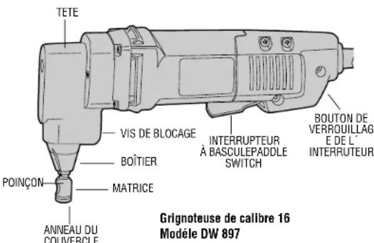
| Intended Use | Cutting flat and slightly corrugated metal |
| Gauge | 16 (max thickness 1.52 mm / 0.060 in) |
| Switch | Rocker switch with continuous mode lock |
| Rotatable head | 3 positions: left, front, right |
| Hole diameter for interior cutting | 19 mm (3/4 in) |
| Template guide | Diameter 13 mm (0.51 in) |
| Power Supply | Electric (mains) |
| Minimum punch length | 69 mm (2.72 in) |
| Approximate weight | 2.5 kg |
| Dimensions (L x W x H) | 300 x 80 x 120 mm |
| Maintenance | Cleaning with compressed air, lubrication of punch, sharpening/replacing punch and die |
| Safety | Safety goggles, gloves, safety shoes; avoid explosive atmospheres; disconnect before adjustment |
| Warranty | 1 year (DeWalt) + 30-day satisfaction money-back guarantee |
| Accessories | Not included; recommended sold at retailers |
Frequently Asked Questions - DW897 DEWALT
User questions about DW897 DEWALT
0 question about this device. Answer the ones you know or ask your own.
Ask a new question about this device
Download the instructions for your Scissors in PDF format for free! Find your manual DW897 - DEWALT and take your electronic device back in hand. On this page are published all the documents necessary for the use of your device. DW897 by DEWALT.
USER MANUAL DW897 DEWALT
D.WALT Industrial Tool Company, P.O. Box 158, 626 Hanover Pike, Hampstead, MD 21074
Printed in Country MAY97-1)
Form No. 384328
DW897/897-220 Copyright © 1997
INSTRUCTION MANUAL
GUIDE D'UTILISATION
IF YOU HAVE ANY QUESTIONS OR COMMENTS ABOUT THIS OR ANY DEWALT TOOL, CALL US TOLL FREE AT: 1-800-4-DEWALT (1-800-433-9258)
IMPORTANT SAFETY INSTRUCTIONS (FOR ALL TOOLS)
⚠ WARNING: When using electric tools, basic safety precautions should always be followed to reduce risk of fire, electric shock, and personal injury, including the following:
READ ALL INSTRUCTIONS
Double Insulation
Double insulated tools are constructed throughout with two separate layers of electrical insulation or one double thickness of insulation between you and the tool's electrical system. Tools built with this insulation system are not intended to be grounded. As a result, your tool is equipped with a two prong plug which permits you to use extension cords without concern for maintaining a ground connection.
NOTE: Double insulation does not take the place of normal safety precautions when operating this tool. The insulation system is for added protection against injury resulting from a possible electrical insulation failure within the tool.
⚠️ CAUTION: WHEN SERVICING USE ONLY IDENTICAL REPLACEMENT PARTS. Repair or replace damaged cords.
Polarized Plugs(DW897)
Polarized plugs (one blade is wider than the other) are used on equipment to reduce the risk of electric shock. When provided, this plug will fit into a polarized outlet only one way. If the plug does not fit fully into the outlet, reverse the plug. If it still does not fit, contact a qualified electrician to install the proper outlet. Do not change the plug in any way.
For All Tools:
- KEEP WORK AREA CLEAN. Cluttered areas and benches invite injuries.
- CONSIDER WORK AREA ENVIRONMENT. Don't expose power tools to rain. Don't use power tools in damp or wet locations. Keep work area well lit.
- GUARD AGAINST ELECTRIC SHOCK. Prevent body contact with grounded surfaces; for example, pipes, radiators, ranges, and refrigerator enclosures.
- KEEP CHILDREN AWAY. All visitors should be kept away from work area. Do not let visitors contact tool or extension cord.
- STORE IDLE TOOLS. When not in use, tools should be stored in dry, and high or locked-up place — out of reach of children.
- DON'T FORCE A TOOL. It will do the job better and safer at the rate for which it was intended.
- USE RIGHT TOOL. Don't force small tool or attachment to do the job of a heavy duty tool. Don't use tool for purpose not intended; for example, don't use circular saw for cutting tree limbs or logs.
- DRESS PROPERLY. Do not wear loose clothing or jewelry. They can be caught in moving parts. Rubber gloves and non-skid footwear are recommended when working outdoors. Wear protective hair covering to contain long hair.
- USE SAFETY GLASSES. Also use face or dustmask if operation is dusty.
- DON'T ABUSE CORD. Never carry tool by cord or yank it to disconnect from receptacle. Keep cord from heat, oil, and sharp edges.
- SECURE WORK. Use clamps or a vise to hold work. It's safer than using your hand and it frees both hands to operate tool.
- DON'T OVERREACH. Keep proper footing and balance at all times.
- MAINTAIN TOOLS WITH CARE. Keep tools sharp and clean for better and safe performance. Follow instructions for lubricating and changing accessories. Inspect tool cords periodically and if
damaged have repaired by authorized service facility. Inspect extension cords periodically and replace if damaged. Keep handles dry, clean, and free from oil and grease.
- DISCONNECT OR LOCK OFF TOOLS when not in use, before servicing, and when changing accessories, such as blades, bits, cutters.
- REMOVE ADJUSTING KEYS AND WRENCHES. Form habit of checking to see that keys and adjusting wrenches are removed from tool before turning it on.
- AVOID UNINTENTIONAL STARTING. Don't carry plugged-in tool with finger on the switch. Be sure the switch is off when plugging in.
- EXTENSION CORDS. Make sure your extension cord is in good condition. When using an extension cord, be sure to use one heavy enough to carry the current your product will draw. An undersized cord will cause a drop in line voltage resulting in loss of power and overheating. The following table shows the correct size to use depending on cord length and nameplate ampere rating. If in doubt, use the next heavier gage. The smaller the gage number, the heavier the cord.
Minimum Gage for Cord Sets
Volts Total Length of Cord In Feet 120V 0-25 26-50 51-100 101-150
240V 0-50 51-100 101-200 201-300
| Ampere Rating | |||||||
| More Than | Not Than | more | AWG | ||||
| 0 | - | 6 | 18 | 16 | 16 | 16 | 14 |
| 6 | - | 10 | 18 | 16 | 14 | 12 | |
| 10 | - | 12 | 16 | 16 | 14 | 12 | |
| 12 | - | 16 | 14 | 12 | Not Recommended | ||
- STAY ALERT. Watch what you are doing. Use common sense. Do not operate tool when you are tired.
-
OUTDOOR USE EXTENSION CORDS. When tool is used outdoors, use only extension cords intended for use outdoors and so marked.
-
CHECK DAMAGED PARTS. Before further use of the tool, a guard or other part that is damaged should be carefully checked to determine that it will operate properly and perform its intended function. Check for alignment of moving parts, binding of moving parts, breakage of parts, mounting, and any other conditions that may affect its operation. A guard or other part that is defective should be properly repaired or replaced by an authorized service center unless otherwise indicated elsewhere in this instruction manual. Have defective switches replaced by authorized service center. Do not use tool if switch does not turn it on and off.
- DO NOT OPERATE portable electric tools near flammable liquids or in gaseous or explosive atmospheres. Motors in these tools normally spark, and the sparks might ignite fumes.
- CAUTION: When drilling or driving into walls, floors or wherever live electrical wires may be encountered, DO NOT TOUCH ANY METAL PARTS OF THE TOOLS! Hold the tool only by insulated grasping surfaces to prevent electric shock if you drive into a live wire.
SAVE THESE INSTRUCTIONS FOR FUTURE USE
Operating Rules for Nibblers
- Always wear safety glasses and protective gloves.
- Wear safety shoes to protect your feet from sharp metal debris on floor.
- Cut material at or below rated capacity. Remember, material thickness increases as gauge number decreases (14 gauge is thicker than 16 gauge). 14 gauge thickness is .075" (1,9 mm); 16 gauge is .060" (1,5 mm).
- Keep all screws tight. Periodically check them for loosening.
- Unplug tool before making any adjustments.
-
Do not put anything into a motor housing opening.
-
Keep tool clean. Blow off any metal debris and dirt from tool.
- Firmly secure the piece of metal to be cut to prevent movement during cutting.
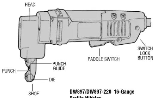
PADDLE SWITCH
To start the tool, depress the paddle switch. To turn the tool off, release the paddle. The switch can be locked on be engaging the lock button located near the rear of the tool while holding the paddle depressed. Always be sure that the tool is not locked on before plugging it in. To turn the tool off when it is locked on, squeeze and release the paddle once.
Operation
TURN OFF TOOL AND DISCONNECT FROM POWER SUPPLY BEFORE MAKING ANY ADJUSTMENTS. Always wear safety glasses and protective gloves.
Lubricate surface of material with oil. The profile nibbler is designed to cut corrugated, flat, and box steel forms.
The tool is factory assembled with the punch oriented forward for cutting flat and shallow corrugated material. To cut deeper corrugated metals and box sections, rotate the head 90° to either side to use tool sideways.
The shoe can be aligned in three positions: left, forward, and right. (See Figure 2).
To rotate the head, loosen the set screw. Turn the head in the desired direction. NOTE: Do not rotate the head in a complete circle as this will change the punch engagement in the die.
Rotate the shoe and turn the set screw in until you feel the set screw engage a recess in the shoe. Tighten the set screw firmly. Periodically recheck this screw for tightness.
Sharpening Punches
Never cut with a blunt, dull punch or die. Punches can be sharpened
up to 1/8" (3mm). To remove the punch, loosen the head set screw about 4-5 turns (See Figure 2). Slide the shoe assembly from the head. Unscrew the punch from the connecting rod bushing. Punch may be resharpened carefully on a bench grinder with a fine grit wheel. Be careful that the punch does not become shorter than the minimum length of 2.44 inches (2-7/16 inches or 61mm). Punches shorter than this will not engage the die sufficiently and must be replaced. The ground face must be square to the punch axis. After grinding, carefully stone the ground edges to remove burrs. Do not round over corners.
Figure 2
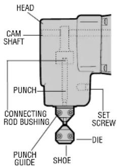
Figure 3

Reassembly of Nibbler Head
Screw the punch fully into the connecting rod bushing. Slide the shoe assembly over the end of the punch and into the head. NOTE: Lubrication groove in punch face must not be exposed at front of shoe. Turn the shoe to desired cut orientation. Tighten set screw. Next, check punch engagement.
Checking Punch Engagement
Since the punch length is now changed, the punch engagement may have to be adjusted. Check punch engagement by placing a flat blade screwdriver in the cam shaft slot and turning the shaft. (See Figure 2) Punch should dip .020" to .04" (.5 to 1.0mm) into the die at the full down stroke position. Too much punch dip into the die will result in a loss of capacity (bottom of punch will not clear die enough on up stroke.)
Punch Engagement Adjustment
If the punch engagement should need adjustment, loosen the set screw and rotate shoe either clockwise (punch deeper into die) or counterclockwise (punch out of die). Tighten set screw firmly. Turn cam shaft with screwdriver in slot to check punch engagement (moving punch fully down). Repeat as necessary.
Die Replacement
If the die becomes dull, replace it. Replace old die by removing two screws at the front (Figure 2). Install new die and tighten screws. Recheck punch engagement and adjust punch depth if necessary.
Wear Plate
This tool is equipped with a wear plate to increase the life of the shoe (See Figure 3). The wear plate fits between the shoe and the punch. Anytime the punch, punch guide or die is removed, inspect
the wear plate. If it is worn, replace it.
To remove the wear plate, disassemble the punch guide and die (Figure 3). Turn cam shaft with screwdriver so that punch is fully up. Slide the wear plate from behind the punch. Insert a new wear plate. Turn the cam shaft with screwdriver to move punch fully down. Replace punch guide and die. Check punch engagement to die. Adjust punch engagement, if necessary.
Maintenance
DISCONNECT TOOL FROM POWER SUPPLY BEFORE PERFORMING ANY MAINTENANCE. Check that the punch and die are sharp. If either is dull, sharpen or replace. Check wear plate and replace if worn. Keep the tool clean. Blow off periodically. Never use solvents or harsh chemicals for cleaning non-metallic parts of the tool. Use a clean, dry rag only. Periodically dip the shoe in oil. This is a precision tool. Use it carefully and store it in a protected place.
Cleaning & Lubrication
Use only mild soap and damp cloth to clean the tool. Never let any liquid get inside the tool; never immerse any part of the tool into a liquid.
Self-lubricating bearings are used in the tool and periodic relubrication is not required. In the unlikely event that service is ever needed, service center addresses are packed with your tool.
Motor Brushes
Brush replacement should be performed by authorized service centers or other qualified service organizations.
Important
To assure product SAFETY and RELIABILITY, repairs, maintenance and adjustment (including brush inspection and replacement) should be performed by authorized service centers or other qualified service organizations, always using identical replacement parts.
Full Warranty
D=WALT heavy duty industrial tools are warranted for one year from date of purchase. We will repair, without charge, any defects due to faulty materials or workmanship. For warranty repair information, call 1-800-4-D=WALT. This warranty does not apply to accessories or damage caused where repairs have been made or attempted by others. This warranty gives you specific legal rights and you may have other rights which vary in certain states or provinces. In addition to the warranty, D=WALT tools are covered by our:
30 DAY NO RISK SATISFACTION GUARANTEE
If you are not completely satisfied with the performance of your D=WALT heavy duty industrial tool, simply return it to the participating seller within 30 days for a full refund. Please return the complete unit, transportation prepaid. Proof of purchase may be required.
POUR TOUT RENSEIGNEMENT SUPPLÉMENTAIRE SUR CET OUTIL OU TOUT AUTRE OUTIL DEWALT, COMPOSER SANS FRAIS LE NUMÉRO:
1 800 4-DeWALT (1 800 433-9258)
Français

IMPORTANTES MESURES DE SÉCURITÉ (POUR TOUS LES OUTILS)
Eje Lázaro Cárdenas No. 18 Local D, Col. Obrera 588-9377
MERIDA
Calle 63 #459-A (91 99) 23 54 90
MONTERREY
Av. Francisco I. Madero Pte. 1820-A (91 83) 72 11 25
PUEBLA
17 Norte #205 (91 22) 46 37 14
QUERETARO
Av. Madero 139 Pte. (91 42) 14 16 60
SAN LOUIS POTOSI
Pedro Moreno #100 Centro (91 48) 14 25 67
TORREON
Blvd. Independencia, 96 pte. (91 17) 16 52 65
VERACRUZ
Prolongación Diaz Miron #4280 (91 29) 21 70 16
VILLAHERMOSA
Constitucion 516-A (91 93) 12 53 17