DW896 - Scissors DEWALT - Free user manual and instructions
Find the device manual for free DW896 DEWALT in PDF.

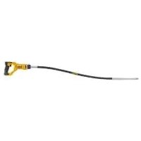
| Product type | Electric nibbler (scissors) |
| Brand | DEWALT |
| Model | DW896 |
| Power supply voltage | 120 V AC, 50/60 Hz |
| Cutting gauge | 16 (steel up to 1.6 mm) |
| Cutting width | 6 mm |
| Starting hole diameter | 13 mm (1/2 in) |
| Double insulation | Yes |
| Polarized plug | Yes |
| Switch type | Paddle switch with lock-off |
| Approximate weight | 1.8 kg |
| Approximate dimensions (L x W x H) | 250 x 80 x 180 mm |
| Construction materials | Steel and reinforced plastic |
| Maintenance | Lubrication every 60 days to 6 months |
| Cleaning | Blow compressed air through vents |
| Motor brushes | Replacement by qualified personnel |
| Warranty | 3-year limited + 1 year free maintenance |
| Mandatory safety | Wear safety glasses |
| Repairability | Authorized DEWALT service centers |
Frequently Asked Questions - DW896 DEWALT
User questions about DW896 DEWALT
0 question about this device. Answer the ones you know or ask your own.
Ask a new question about this device
Download the instructions for your Scissors in PDF format for free! Find your manual DW896 - DEWALT and take your electronic device back in hand. On this page are published all the documents necessary for the use of your device. DW896 by DEWALT.
USER MANUAL DW896 DEWALT
D=WALT Industrial Tool Co., 701 East Joppa Road, Baltimore, MD 21286
(APR04) Form No. 384263-00
DW896
Copyright © 1997, 2004
The following are trademarks for one or more D _E WALT power tools: the yellow and black color scheme; the “D” shaped air intake grill; the array of pyramids on the handgrip; the kit box configuration; and the array of lozenge-shaped humps on the surface of the tool.
Questions? See us on the World Wide Web at www.dewalt.com
INSTRUCTION MANUAL
GUIDE D'UTILISATION
IF YOU HAVE ANY QUESTIONS OR COMMENTS ABOUT THIS OR ANY DEWALT TOOL, CALL US TOLL FREE AT: 1-800-4-DEWALT (1-800-433-9258)
Important Safety Instructions
WARNING: When using electric tools, basic safety precautions should always be followed to reduce risk of fire, electric shock, and personal injury, including the following:
READ ALL INSTRUCTIONS
Double Insulation
Double insulated tools are constructed throughout with two separate layers of electrical insulation or one double thickness of insulation between you and the tool's electrical system. Tools built with this insulation system are not intended to be grounded. As a result, your tool is equipped with a two prong plug which permits you to use extension cords without concern for maintaining a ground connection. NOTE: Double insulation does not take the place of normal safety precautions when operating this tool. The insulation system is for added protection against injury resulting from a possible electrical insulation failure within the tool.
▲ CAUTION: WHEN SERVICING USE ONLY IDENTICAL REPLACEMENT PARTS. Repair or replace damaged cords.
Polarized Plugs
Polarized plugs (one blade is wider than the other) are used on equipment to reduce the risk of electric shock. When provided, this plug will fit in the polarized outlet only one way. If the plug does not fit fully into the outlet, reverse the plug. If it still does not fit, contact a qualified electrician to install the proper outlet. Do not change the plug in any way.
Safety Instructions For All Tools
- KEEP WORK AREA CLEAN. Cluttered areas and benches invite injuries.
-
CONSIDER WORK AREA ENVIRONMENT. Don't expose power tools to rain. Don't use power tools in damp or wet locations. Keep work area well lit. Do not use tool in presence of flammable liquids or gases.
-
GUARD AGAINST ELECTRIC SHOCK. Prevent body contact with grounded surfaces. For example; pipes, radiators, ranges, and refrigerator enclosures.
- KEEP CHILDREN AWAY. Do not let visitors contact tool or extension cord. All visitors should be kept away from work area.
- STORE IDLE TOOLS. When not in use, tools should be stored in dry, and high or locked-up place — out of reach of children.
- DON'T FORCE TOOL. It will do the job better and safer at the rate for which it was intended.
- USE RIGHT TOOL. Don't force small tool or attachment to do the job of a heavy-duty tool. Don't use tool for purpose not intended.
- DRESS PROPERLY. Do not wear loose clothing or jewelry. They can be caught in moving parts. Rubber gloves and non-skid footwear are recommended when working outdoors. Wear protective hair covering to contain long hair.
- USE SAFETY GLASSES. Also use face or dust mask if operation is dusty.
- DON'T ABUSE CORD. Never carry tool by cord or yank it to disconnect from receptacle. Keep cord from heat, oil, and sharp edges.
- SECURE WORK. Use clamps or a vise to hold work. It's safer than using your hand and it frees both hands to operate tool.
- DON'T OVERREACH. Keep proper footing and balance at all times.
- MAINTAIN TOOLS WITH CARE. Keep tools sharp and clean for better and safer performance. Follow instructions for lubricating and changing accessories. Inspect tool cords periodically and if damaged, have repaired by authorized service facility. Inspect extension cords periodically and replace if damaged. Keep handles dry, clean, and free from oil and grease.
-
DISCONNECT OR LOCK OFF TOOLS when not in use, before servicing, and when changing accessories, such as blades, bits, cutters.
-
REMOVE ADJUSTING KEYS AND WRENCHES. Form habit of checking to see that keys and adjusting wrenches are removed from tool before turning it on.
- AVOID UNINTENTIONAL STARTING. Don't carry tool with finger on switch. Be sure switch is off when plugging in.
- EXTENSION CORDS. Use only 3-wire extension cords that have 3-prong grounding-type plugs and 3-pole receptacles that accept the tool's plug. Replace or repair damaged cords. Make sure your extension cord is in good condition. When using an extension cord, be sure to use one heavy enough to carry the current your product will draw. An undersized cord will cause a drop in line voltage resulting in loss of power and overheating. The following table shows the correct size to use depending on cord length and nameplate ampere rating. If in doubt, use the next heavier gage. The smaller the gage number, the heavier the cord.
120V 0-25 26-50 51-100 101-150
240V 0-50 51-100 101-200 201-300 - OUTDOOR USE EXTENSION CORDS. When tool is used outdoors, use only extension cords intended for use outdoors and so marked.
- STAY ALERT. Watch what you are doing. Use common sense. Do not operate tool when you are tired.
- CHECK DAMAGED PARTS. Before further use of the tool, a guard or other part that is damaged should be carefully checked to determine that it will operate properly and perform its intended function. Check for alignment of moving parts, binding of moving parts, breakage of parts, mounting, and any other conditions that may affect its operation. A guard or other part that is damaged should be properly repaired or replaced by an authorized service center unless otherwise indicated elsewhere in this instruction
Minimum Gage for Cord Sets
Volts Total Length of Cord in Feet
Ampere Rating
| More Than | Not Than | more | AWG | |||
| 0 | - | 6 | 18 | 16 | 16 | 14 |
| 6 | - | 10 | 18 | 16 | 14 | 12 |
| 10 | - | 12 | 16 | 16 | 14 | 12 |
| 12 | - | 16 | 14 | 12 | Not Recommended | |
manual. Have defective switches replaced by authorized service center. Do not use tool if switch does not turn it on and off.
SAVE THESE INSTRUCTIONS
Motor
Your DeWALT tool is powered by a DeWALT built motor. Be sure your power supply agrees with the nameplate marking. Voltage decrease of more than 10% will cause loss of power and overheating. All DeWALT tools are factory tested; if this tool does not operate, check the power supply.
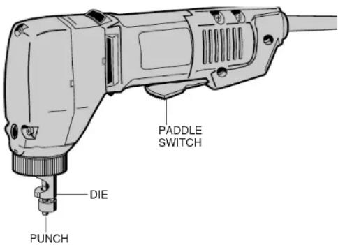
Switch
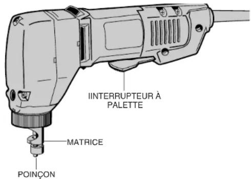
To start tool, depress the paddle switch (Figure 1). To turn the tool off, release the paddle. The paddle switch can be locked on by engaging the lock button located near the rear of the tool, while holding the paddle depressed. Always be sure that the tool is not locked on before plugging in. To turn the tool off when it is locked on, squeeze and release the paddle once.
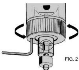
Setting the Cutter
TURN OFF TOOL AND DISCONNECT FROM POWER SUPPLY.
The cutter can be set to cut in any direction relative to the body. Release the set screw in the knurled ring (Figure 2) with key provided and unscrew the ring by rotating in a counterclockwise direction as viewed from the cutter.
Loosen ring just enough to be able to rotate the die. Set the die so that the connecting web (Figure 3) is on the opposite side of the direction of cut. Fully tighten the knurled ring and lock by tightening the set screw.
Operation
NOTE: ALWAYS WEAR SAFETY GLASSES.
Make sure the knurled ring (Figure 2) is tight prior to use. Keep fingers away from cutter and other moving parts.

natural_image
Mechanical component diagram showing a valve assembly with directional arrows indicating motion (no text or symbols)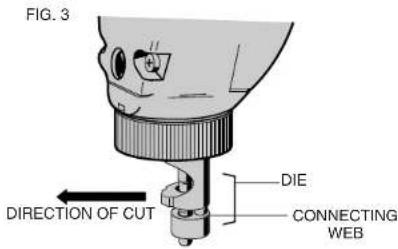

natural_image
Illustration of a sewing machine needle stitching fabric (no text or symbols)FIG. 5
natural_image
Illustration of a power tool cutting through a workpiece (no text or symbols visible)
natural_image
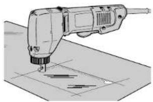
Illustration of a hand operating a drilling rig to lift a circular component on a flat surface (no text or symbols)The nibbler cuts a slot in the work 6mm wide so remember to compensate for this when marking out and calculating material requirements.
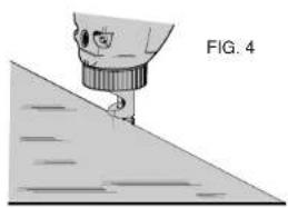
When starting the cut from an edge, place the nibbler so the slot in the die engages the work and the edge is against the punch, which is the moving part when cutting (Figure 4).
Start the nibbler by depressing the paddle switch. Hold the body parallel to the work surface.
Exert only enough forward pressure to start the nibbler cutting and maintain this pressure. Extra pressure will not increase the rate of cut as the amount of material removed at each cutting stroke is fixed and the rate of cut is dependent only on the speed of the nibbler. The cutting line of the work should be lightly coated with oil to lubricate the punch and die while cutting.
NOTE: Punch and die should be lubricated by immersing in a good quality cutting oil approximately every 30 feet of cutting.
When the cut is to be started or finished within the periphery of the work, a 13mm (1/2") hole must first be drilled in the work at the start or finish point. This enables the die to be entered or withdrawn as it is larger in diameter than the slot being cut in the work (Figure 5).
Circular holes should be cut in the manner shown in Figure 6, starting at the 13mm (1/2") diameter hole within the circle.
Punch and Die Replacement
After a period of cutting, the punch will become blunted and require replacement. At the same time, check the die for sharpness and replace if necessary.
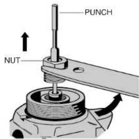
To remove the die, release the knurled ring (Figure 7). Having removed the die, rotate the motor by turning the armature fan, accessible through the side cooling slot, until the punch retaining nut is clear of the face of the gearbox. With the spanner provided, release this nut counterclockwise and remove the punch, Figure 8. Assemble in reverse order.
Keep your nibbler as clean as possible by wiping with a clean cloth and occasionally blowing air through it.
Cleaning
Blowing dust and grit out of the main housing by means of air hose is recommended and may be done as often as dirt is seen collecting in and around the ventilator vents. The motor should be running while air is being blown into the air vents.
Lubrication
DeWALT tools are properly lubricated at the factory and are ready to use. Tools should be relubricated regularly every 60 days to 6 months, depending on usage. Tools used constantly on production or heavy-duty jobs and tools exposed to heat may require more frequent lubrication. This lubrication should only be attempted by trained power tool repairmen such as those at DeWALT certified service centers.
Motor Brushes
When the brushes on this tool become worn out, the tool will automatically stop and prevent damage to the motor. Brush replacement should be performed by DeWALT service centers.
Accessories
Recommended accessories for use with your tool are available at extra cost from your distributor or local service center.
▲ CAUTION: The use of any non-recommended accessory may be hazardous.
Repairs
To assure product SAFETY and RELIABILITY, repairs, maintenance and adjustment (including brush inspection and replacement) should be performed by authorized service centers or other qualified service organizations, always using identical replacement parts.
Three Year Limited Warranty
DEWALT will repair, without charge, any defects due to faulty materials or workmanship for three years from the date of purchase. This
FIG. 7
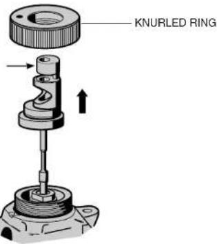
FIG. 8
warranty does not cover part failure due to normal wear or tool abuse. For further detail of warranty coverage and warranty repair information, visit www.dewalt.com or call 1-800-4-D ≤ WALT (1-800-433-9258). This warranty does not apply to accessories or damage caused where repairs have been made or attempted by others. This warranty gives you specific legal rights and you may have other rights which vary in certain states or provinces.
In addition to the warranty, DeWALT tools are covered by our:
1 YEAR FREE SERVICE
DeWALT will maintain the tool and replace worn parts caused by normal use, for free, any time during the first year after purchase.
90 DAY MONEY BACK GUARANTEE
If you are not completely satisfied with the performance of your DEWALT Power Tool, Laser, or Nailer for any reason, you can return it within 90 days from the date of purchase with a receipt for a full refund – no questions asked.
FREE WARNING LABEL REPLACEMENT: If your warning labels become illegible or are missing, call 1-800-4-DEWALT for a free replacement.
POUR TOUT RENSEIGNEMENT SUPPLÉMENTAIRE SUR CET OUTIL OU TOUT AUTRE OUTIL DEWALT, COMPOSER SANS FRAIS LE NUMÉRO:
1 800 4-DEWALT (1 800 433-9258)
natural_image
Mechanical component diagram showing a valve assembly with rotating arrows (no text or symbols)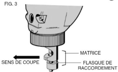
natural_image
Illustration of a sewing machine needle stitching fabric (no text or symbols)FIG. 5

natural_image
Illustration of a power tool cutting through a workpiece (no text or symbols visible)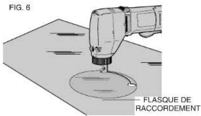
natural_image
Mechanical assembly diagram showing a valve or pump with directional arrows indicating motion (no text or symbols)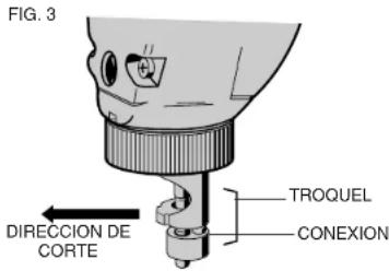

natural_image
Illustration of a sewing machine needle stitching fabric (no text or symbols)FIG. 5

natural_image
Illustration of a power tool cutting through a grid on a surface (no text or symbols)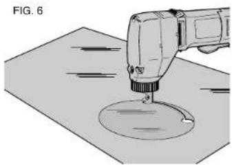
natural_image
Illustration of a hand operating a drilling rig on a workbench (no text or symbols visible)Local D, Col. Obrera
MERIDA, YUC
Calle 63 #459-A - Col. Centro (999) 928 5038
MONTERREY, N.L.
Av. Francisco I. Madero No.831 - Col. Centro (81) 8375 2313
PUEBLA. PUE
17 Norte #205 - Col. Centro (222) 246 3714
QUERETARO, QRO
Av. Madero 139 Pte. - Col. Centro (442) 214 1660
SAN LUIS PÓTOSI, SLP